
how does a mechanical seal work price

www.piprocessinstrumentation.com is using a security service for protection against online attacks. An action has triggered the service and blocked your request.
Please try again in a few minutes. If the issue persist, please contact the site owner for further assistance. Reference ID IP Address Date and Time 511e3d8fdc32fa9284198b8c0d6b43df 63.210.148.230 03/04/2023 05:29 AM UTC
To improve the performance of any piece of equipment requires a complete understanding of its operation and the effect on its component parts. The definition of mechanical reliability is the probability that a component, device or system will perform its prescribed service without failure for a given time when operated correctly in a specified environment.
A component part is the smallest part that would normally be replaced. A device, such as a pump, compressor, agitator, mixer, etc., is made up of many component parts. A system, such as a process plant, refinery, power plant, ship, etc. is made up of many devices. Thus, when a critical component fails, it can have a tremendous economic impact, not only on the device in which it is installed, but on an entire system. A mechanical seal is just such a component. The major causes for seal failure on a pump are a result of the following conditions:
As the shaft of a pump begins to rotate, a small fluid film develops between the seal faces along with unwanted frictional heat from the seal surfaces in sliding contact. If the amount of frictional heat developed at the seal faces cannot be removed, then the liquid being sealed will flash to a gas or begin to carbonize. Developed frictional heat at the seal faces must be removed.
Each contacting seal has an operating envelope, as illustrated in Fig. 1. The upper limit is determined by wear. More importantly, a seal must operate at a temperature to prevent boiling of the liquid sealed. Operation within the envelope will result in excellent seal life.
Common cryogenic fluids such as argon, nitrogen and oxygen are stored near their atmospheric pressure and pumped near their normal boiling points. These are the most common cryogenic fluids used in industry. The fluids are delivered by over-the-road trucks to industrial users and hospitals. Each truck uses a single stage centrifugal pump driven by a hydraulic motor to move these liquids from the truck to the storage tanks. One fleet operator with 25 trucks began an aggressive program to reduce failures and improve equipment reliability. An analysis of the operation’s seal life and repair costs is shown in Table I. Not only were the maintenance costs excessive, there were also financial losses when deliveries could not be made.
Upon reviewing the seals that failed in this cryogenic service, it became clear that at certain times during the operation of the pump the fluid at the seal faces was flashing and extreme wear and heat checking occurred on the mating ring in the seal assembly. Further complicating the problem was the cool-down period for the equipment. Both the pump and piping had to be cooled down to the liquid gas temperature. Any rise in product temperature could have led to the pump cavitating and the seal running dry.
To be successful in operating near the boiling point of the fluid being sealed requires a seal that eliminates the frictional heat from the sliding services in contact. A seal that is in a controlled environment will allow the liquid to turn to a gas without violent flashing. The properties of the cryogenic fluids to be sealed are given in Table II.
The success from using a non-contacting seal can be explained by reviewing the vapor pressure curve for nitrogen shown in Fig. 2. In this case, nitrogen that is being transported by tank truck is normally at 30 psig/2bar and -320 F/-190 C. When using a contacting seal, the temperature increase at the seal faces is sufficient to start the boiling process at pumping pressure. In an uncontrolled environment such as a contacting seal, continuous flashing damages the seal faces, shortening seal life. During operation of the non-contacting seal design, the temperature rise at the seal faces is only a few degrees, eliminating violent flashing of the cryogenic liquid.
The savings associated with improved seal reliability for the 25 trucks in this cryogenic delivery fleet operation are shown in Table I. These savings were substantial enough to allow the purchase of a new tank truck.
A poor mechanical environment requires a seal to move an abnormal amount during operation. The motion transmitted to a seal can be angular or axial. The most common cause of angular motion is piping stresses transferred to the pump casing. This type of loading will result in premature seal failure.
In one case, a power plant experienced a seal failure every three months. Measurements taken on the pump casing at full operating pressure and temperature indicated 0.016” of deflection. This, in turn, distorted the seal chamber and mating face.
The estimated angular distortion or out-of-squareness at the seal face was greater than 0.012”. The shaft was turning at 1800 RPM. This meant that the seal had to flex 0.012” of travel 1800 times/per minute.
The solution to this problem was to add an expansion joint in the piping in the suction line to the pump, which would eliminate the high load being transferred to the pump casing. Clearly, this failure had nothing to do with the design of the component parts of the seal. The savings per year per pump were estimated to be $18,000.
Axial motion from thermal growth of equipment can cause the seal to run solid, resulting in failure. This is more likely to occur on large pieces of equipment. High thrust bearing wear might be expected on a high-speed boiler feed pump, where, over time, it could lead to seal failure.
A ship’s power plant, with low boiler demands, is a prime example of where axial shaft motion might occur. The greater the wear on the thrust bearing, the more axial travel the seal must handle. When the travel is excessive, the seal will run solid and fail. The cost to the ship’s power plant would be excessive.
A synthetic fuel processing plant implemented a program to reduce maintenance costs and improve the reliability of two large compressors vital to plant operation. The gas compressors can reach process temperatures of 650 F and 370 psia respectively. Steam is used as a buffer fluid to prevent gas in the compressor from reaching atmosphere. Steam pressure is 10 psi above the process gas pressure. At these conditions, steam cutting of the existing sealing surfaces was occurring. Annual maintenance to replace the existing seal was $25,000. Annual bearing repair was $12,500. The annual cost of steam was $100,000.
Review of existing non-contact seal technology determined that it could be redesigned to handle high temperatures. Both compressors were converted to the new technology. Each compressor subsequently operated successfully for 10 years without any major work required. The $2,470,000 in savings over this time period reflected a significant payback from implementation of dry-gas sealing technology for high temperature services. The first compressor will be overhauled this year and the second compressor next year.
As shown by these short case study examples, substantial savings can be achieved by analyzing the reasons for short equipment life and applying the best solution. By the same token, improper specification, application and maintenance of critical components like mechanical seals can lead to reduced reliability and substantial losses for an operation. MT
James P. (Jim) Netzel is an engineering consultant based in Yorkville, IL. His 40+ years of experience in the design and application of mechanical seals includes 20 years of service as chief engineer at John Crane, in Morton Grove, IL. During his career, Netzel has authored (and presented) numerous technical papers through the International Pump Symposium, STLE, ASME, BHRA, AISE, SAE and various trade publications. He also has written chapters on seals and sealing systems for The Pump Handbook, The Centrifugal Pump Handbook and The Compressor Handbook. This article is based on a presentation delivered at MARTS 2008. E-mail: jpnetzel@comcast.net
1. Wallace, N.M, Redpath, D., and Netzel, J.P., 2000, “Toward Reduced Pump Operating Costs,” 17th International Pump Users Symposium Texas A&M, Houston, TX
2. Netzel, J.P., Redpath, D., and Wallace, N.M., 2001, “Toward Reduced Pump Operating Costs – Part 2 Avoiding Premature Failures,” 18th International Pump Users Symposium, Texas A&M, Houston, TX
3. Netzel, J.P., and Voigt, J., 2001, “Reducing Life Cycle Costs For Pumps Handling Cryogenic Fluids,” 18th International Pump Users Symposium, Texas A&M, Houston, TX

Many Northern California refineries still use packing for their seals on centrifugal pumps because it’s simple and cheap. But, eventually, you’ll have to evaluate the cost and efficiency of continuing to use gland packing seals. The fundamental question to consider is whether is it beneficial to replace them with mechanical seals.
While there are definite advantages to gland packing, I’ll admit my bias for mechanical seals and seal support systems. I’ve seen hundreds of situations where mechanical seals and their seal support systems improved pump and process reliability while lowering long-term costs. So, to provide some guidance on the mechanical seals vs packing question, I explain the benefits of upgrading to mechanical seals and support systems.
Gland packing, or compression packing as it is sometimes called, has been used to prevent centrifugal pump leakage for more than a century. Braided, lubricated rings encircle the impeller shaft within the aptly-named stuffing box. Packing rings are adjusted to allow minimal leakage of process fluid across the impeller shaft to provide cooling and lubrication. For heavier process fluids, such as slurries with poor lubricating characteristics, an external water flush delivered at pressure to the stuffing box provides the required lubrication and cooling.
While the installation of packings is relatively simple, ongoing maintenance can be problematic. Through normal operations the packing wears and some lubrication is lost, resulting in leakage. Tightening squeezes the packing rings to restore packing integrity. Packings should be adjusted at scheduled intervals but stressed maintenance budgets often, in turn, stretch the maintenance intervals.
And determining the proper adjustment is becoming a lost art. As the number of centrifugal pumps with packing declines, fewer maintenance personnel have the requisite skills. Overtightening packing resolves leakage but also increases friction and heat between shaft and packing, leading to increased wear of the packing and shaft. This results in the need for more frequent packing adjustments, if not packing replacements. More friction also places a greater load on the pump motor, increasing energy costs.
Undertigthened packings quickly manifest as leakage. If you’re pumping plant water, it’s not a major problem, though it is certainly inefficient. If you’re pumping wastewater or hydrocarbons regulated by the Cal/OSHA or BAAQMD, you’re risking sanctions—and reputation.
While mechanical seals lack the simplicity of packing, when comparing the two options, the range of designs and level of reliability offer considerable advantages. The variety of mechanical seals and their seal support systems allow refineries to select the solutions that match the specific process and pump requirements. Covering the spectrum of process needs, from basic transport of plant water to the most demanding high-temperature hydrocarbon processes, there are seals and seal support systems to meet the need.
Process-side seals and seal support systems, for instance, use process fluids to flush, cool, and lubricate the seal. Optional components for removing particulates from process fluid or providing additional cooling further enhance the reliability of these solutions.
Dual seals and seal support systems, however, deliver buffer or barrier fluids from an external source—plant nitrogen, water/ glycol, oil—to ensure maximum sealing safety by separating process fluid from the atmosphere. Configuration and component options offer a variety of methods for managing dual seal pressure as well as condensing and non-condensing process fluid. For process fluids that present environmental risk, dual seals and their support systems offer the maximum protection against leakage.
Atmospheric side seals and seal support systems similarly deliver an external quench, like nitrogen or water/ steam, to the atmospheric side of the seal to prevent icing, coking, other forms of crystallization.
Each of the various seal and seal support system arrangements can include instrumentation and components that enhance efficiency and reliability. Temperature, pressure, and flow gauges provide immediate metrics regarding performance. Optimally located valves and vents facilitate easy maintenance. In comparison to packings, mechanical seals and support systems give reliability and maintenance engineers a clear understanding of performance and alert to “out-of-the-norm” conditions.
It’s true that mechanical seals and support systems have greater initial installation costs. However, once installed, these solutions specifically designed for the variety of refinery processes provide greater efficiency, cost savings, and a higher margin of safety throughout their lifetime. Consider these points to evaluate the pros and cons of mechanical seals vs packing.
❏ Proactively identify and remedy problems with system designs that facilitate condition-based maintenance practices that extend mechanical seal life.
You’re very unlikely to do a wholesale replacement of packing gland seals with mechanical seals and support systems. However, a review of pump maintenance records may reveal a number of pumps deserving an upgrade. Problematic leaks, repetitive repairs, and fugitive emissions are efficiency, cost, and safety issues that can be remedied with the right mechanical seal and seal support systems.
Once you’ve identified the pumps with packing gland seals that deserve upgrades, work with your mechanical seal supplier to determine which type of mechanical seal best fits each pump. Then contact us at Swagelok. With local design, fabrication, assembly, and supply facilities in the Bay Area, we’re only minutes away from your refinery.
We’ll meet at your site and gather specific information regarding your requirements with considerations for the many old pumps currently using packing that have infrastructure factors. Based on that information, we’ll provide you detailed design drawings and technical specifications on components.
Upon approval, we’ll fabricate and test your seal support systems in accordance with our ISO 9001 quality management certification. You’re assured of the finest quality materials, design, and service with our Lifetime Warranty, one of the best in the industry.
To learn howSwagelok Northern California can help you select the right seal support system when you"re upgrading packing gland seals to mechanical seals,Contact our team today by calling 510-933-6200.
Paul holds a B.S. in Mechanical Engineering from North Dakota State University. Before joining Swagelok Northern California, he was the West Coast Regional Sales Manager for an organization based in Illinois involved in pneumatic and hydraulic applications where he supervised product distribution throughout the western United States, Canada, and Mexico. While in this role, he was able to help provide technical and application-specific expertise to customers and distribution to drive specifications.

Please try again in a few minutes. If the issue persist, please contact the site owner for further assistance. Reference ID IP Address Date and Time 229d17606ec3de853d91e43b7761c5b0 63.210.148.230 03/04/2023 05:29 AM UTC
Another area that can be evaluated is life cycle cost or total cost of ownership. Life cycle cost analyses for mechanical seals are often made using labor and material costs and their economic impact on production throughput. An area of evaluation with increased focus is energy costs and carbon footprint.
A tool is now available from FSA to evaluate multiple sealing systems and a wide array of parameters to assist in identifying the best sealing system. Alternative mechanical sealing systems can be compared as each alternative will likely have an impact on reliability, cost and energy consumption. In addition, alternatives to mechanical seals, such as compression packing, can also be compared. The FSA"s Life Cycle Cost Estimator Tool is available online at http://www.fluidsealing.com/lifecycle.html and can provide excellent insight into choosing the optimum sealing system.
The Life Cycle Cost Estimator Tool can easily be used by inputting specific data or accepting the default data. Up to three sealing systems can be analyzed at any one time. Data inputs are separated into four areas—equipment, plant, seal and support system information. A summary of the data inputs is below:Equipment information
An existing centrifugal pump is being investigated for a new sealing device. The pump returns condensate to the boiler section of the plant. Previous mechanical seals failed due to condensate flashing at the seal faces resulting in poor seal face lubrication and overheating from the resultant frictional heat. The question is which sealing system option is the best choice for the application as each of these options vary in their initial cost, maintenance costs and operating costs.
Using an API Plan 32 flush to cool the process fluid in the seal chamber is among the many options for sealing this pump. An external flush fluid, typically at a lower temperature, is injected into the seal chamber to cool the temperature of the process.
Another option is to use an API Plan 21 and direct fluid from the discharge of the pump into a heat exchanger to cool the process fluid. The cooled discharge fluid is then used to flush the seal chamber and replace the hot process fluid with cooled fluid. Significant cooling can be achieved from this environmental control.
Another option is to use a single seal specifically engineered to reduce frictional heat generation in hot water service. Hot water is difficult to seal without cooling as it is a poor lubricant and can easily vaporize between the seal faces. By engineering a seal to provide greater film thickness at the seal faces and modifying the balance ratio, these issues are minimized without the need for cooling. An API Plan 11 is often used to promote circulation and increase pressure in the stuffing box.
So if we compare three sealing systems, Plan 32 Flush, Plan 21 Discharge Recirculation and Plan 11 Engineered Seal for the following pump, which has the lowest life cycle cost and lowest energy consumption over a 15 year period? The condensate is at 200 degrees F and is being pumped at 1,750 rpm with a 2.50-inch diameter shaft. Cooling and flush water is available at 70 degrees F. Each sealing system is estimated to have a mean time between repair (MTBR) of 36 months, but the engineered single seal"s acquisition cost is twice that of the other seal option.
The engineered seal that does not require Plan 21 cooling or Plan 32 flush is clearly a better choice when life cycle costs and power consumption are used in the analysis. Due to the cooling effect of the hot condensate process and the need to reheat the process back to temperature, Plan 32 and Plan 21 are quite costly. The current MTBR is low due to the fact that the seal is not designed for a fluid operating close to its vaporization fluid and generates too much frictional heat. An engineered seal for this application will increase MTBR and does not require cooling. Other options such as seals with self-contained pumping rings, Plan 23, and dual seals can also be analyzed.
Take advantage of the usefulness of this tool to analyze applications in current plants or future ones as well. By working with a mechanical seal specialist, you can drive increases in plant efficiencies and lower operating costs with real data.
"Sealing Sense” is produced by the Fluid Sealing Association (FSA) as part of our commitment to industry consensus technical education for pump users, contractors, distributors, OEMs and reps. As a source of technical information on sealing systems and devices and in cooperation with the European Sealing Association (ESA), FSA also supports the development of harmonized standards in all areas of fluid sealing technology. The education is provided in the public interest to enable a balanced assessment of the most effective solutions to pump technology issues on rational total life cycle cost (LCC) principles.
The Mechanical Seal Division of the FSA is one of six with a specific product technology focus. As part of their educational mission, they develop publications such as the Mechanical Seal Handbook, a primer intended to complement the more detailed manufacturer"s documents produced by the member companies. This document served as the basis for joint development of the more comprehensive Hydraulic Institute publication Mechanical Seals for Pumps: Application Guidelines. Joint FSA/ESA publications such as the Seal Forum, a series of case studies in pump performance, are another example as is the Life Cycle Cost Estimator, a web-based software tool for determination of pump seal total life cycle cost. The Sealing Systems Matter initiative was also launched to support the case for choosing mechanical seals that optimize life cycle cost, energy usage, reliability, safety and environmental compliance.
Five performance factors affect the life of a mechanical seal and guide the determination of an optimum replacement cycle for that seal. They also lead to improved seal life and mean time between repair (MTBR), thereby reducing the Life Cycle Cost (LCC) of the pump population.
The third factor is published mechanical seal application limits, typically defined by pressure, speed and temperature, are prone to misinterpretation.
Most seal manufacturers say that operation of the seal at one of these limits will result in a minimum life span of two years; three years with some seal types such as those specified in Standard API 682. The published limits, while reliable for steady state operation, may be overstated or unreliable for cyclic operation. An exception may be API 682 seals, which specifically address that shortcoming by including a series of cyclic tests to qualify a specific seal type for a range of services.
Generally, no fixed rules exist on how much particular transient-pressure, speed, temperature, gas or solid entrapment, or vibration a seal can tolerate. Expert advice is needed in this area.
The amount a seal face deflects during a transient depends on several factors, including the magnitude and rate of the transient, and the robustness or strength of the seal face. The bottom line is that seal face deflections occur as operating conditions change and may either improve or starve lubrication of the seal faces. A reliable seal is one having a low degree of sensitivity to the expected or unexpected transients. The sensitivity of a seal can be defined by its ability to maintain more or less parallel seal faces during all possible transients.
Sensitivity can also be controlled by properly selecting the materials and the environmental control system. For example, seals with hard/hard face combinations, such as tungsten carbide (WC) and silicon carbide (SiC), which are preferred for dirty fluids or in some cases for high pressures, are very vulnerable to complete or partial loss of the fluid film. Any type of damage to these materials, when run against each other, is typically unrecoverable and only gets worse as time progresses.
New face materials and treatment technologies, such as diamond coatings, promise significant improvement in this area. On the other hand, hard/soft combinations with carbon-graphite as the wearing material offer the distinctive advantage that they can carry much higher loads, sustain longer periods of inadequate lubrication and, most importantly, more readily recover after damage to the carbon-graphite face.
Silicon carbide against a hard carbon-graphite is generally accepted to have one of the highest load capability limits of the readily available materials, best tolerates dry running and, therefore, should be the preferred material combination for many applications.
Without question, an application becomes more difficult and risky when using a larger shaft diameter, faster speed, and higher temperature, pressure and solids content. It is imperative that the robustness of the faces and their ability to dissipate heat efficiently are optimized accordingly.
In many tough applications, it may be wise to consider custom engineered mechanical seals that are designed specifically to deal with unusual events or predefined operating modes of the equipment. Different face designs and lubrication technologies can be selected to increase the life of the faces.
Seal life well in excess of three years is possible for the large majority of applications. The seal face shown in Figure 1 is an example of a robust design that is used in high pressure or speed applications with the ability to handle severe transients and periods of inadequate lubrication. The carbon-graphite face is shrunk-fit into a metal housing and reinforced at the inside diameter with a hardened steel ring. The API 682 and Hydraulic Institute publication Mechanical Seals for Pumps: Application Guidelines offers good rules for specifying an engineered seal.
Because seals operate in these favorable lubrication regimes, energy consumption is minimized, which makes seal operation more economical. The amount of leakage is typically a few milliliters per day or less and not visible. This may be significantly higher for special applications involving high pressures, speeds or large shaft diameters. Consult your seal vendor for the calculation of expected leak rates.
Mechanical seals meet today"s emission limitations in the vast majority of applications. Predicting the leakage and friction behavior for any given application is possible with a good degree of accuracy, which helps set operator guidelines for normal, questionable, and failure behaviors of the seal.
The leak rate increases or decreases when conditions such as pressure, temperature, or speed are changed. This means the leak rate varies depending on how the pump is operated and how responsive the seal faces are to any transient operating conditions. The key to a low and consistent leakage pattern is to maintain face flatness. The Key Performance Indicators (KPIs) of the seal may differ depending on the face technology and materials used.
Any given application usually has several solutions that vary widely in cost and benefits. Seal vendors often promote unique features to enhance or optimize the lubrication of the faces. Some OEMs promote hard/hard combinations for high pressure applications, whereas others uphold the hard/soft approach. Each differs in their ability to cope with unusual events, and the best choice is not always evident.
The operating environment can be manipulated or controlled by selecting and applying a suitable system from a wide choice of methods - and that is almost as important as the seal itself. Most seals need a flushing system to evacuate the heat developed by the seal. If this system malfunctions it may cause problems. "A cool seal is a happy seal" remains true for the majority of applications.
Some fluids may change state as pressure or temperature changes. In the seal chamber the faces are exposed to the suction or discharge conditions of the pump, while at the seal face gap the fluid pressure reduces and its temperature increases. At the exit of the seal faces, the pressure and temperature are close to ambient. The point here is that as pressure and temperature change, the fluid properties may be significantly altered and possibly cause trouble for the seal if not addressed when selecting the seal and control system.
Environmental control systems can be applied to prevent or minimize the negative affect of certain transients, remove the frictional heat of the faces, reduce the presence of solids in the flush flow, improve conditions to prevent vaporization or freezing of the fluid. Most importantly, they minimize the consequences of a failure to the surrounding environment.
A wide choice of flush plans is included in ANSI, API and ISO standards. The variety of seal types and materials, combined with a wide array of flush plans, can make seal selection quite challenging. Helpful hints and tools, such as the FSA Seal Life Cycle Cost Estimator, can be found on www.fluidsealing.com. This tool can compare a wide variety of seal types and systems to aid with effective seal system selection.
Selecting the "Most Effective Sealing Technology" requires a sound understanding of what drives seal performance behavior . . . not only under normal operating conditions, but more importantly, under abnormal conditions.
A mechanical seal is simply a method of containing fluid within a vessel (typically pumps, mixers, etc.) where a rotating shaft passes through a stationary housing or occasionally, where the housing rotates around the shaft.
When sealing a centrifugal pump, the challenge is to allow a rotating shaft to enter the ‘wet’ area of the pump, without allowing large volumes of pressurized fluid to escape.
To address this challenge there needs to be a seal between the shaft and the pump housing that can contain the pressure of the process being pumped and withstand the friction caused by the shaft rotating.
Before examining how mechanical seals function it is important to understand other methods of forming this seal. One such method still widely used is Gland Packing.
Packing needs to press against the shaft in order to reduce leakage – this means that the pump needs more drive power to turn the shaft, wasting energy.
The stationary part of the seal is fitted to the pump housing with a static seal –this may be sealed with an o-ring or gasket clamped between the stationary part and the pump housing.
The rotary portion of the seal is sealed onto the shaft usually with an O ring. This sealing point can also be regarded as static as this part of the seal rotates with the shaft.
One part of the seal, either to static or rotary portion, is always resiliently mounted and spring loaded to accommodate any small shaft deflections, shaft movement due to bearing tolerances and out-of-perpendicular alignment due to manufacturing tolerances.
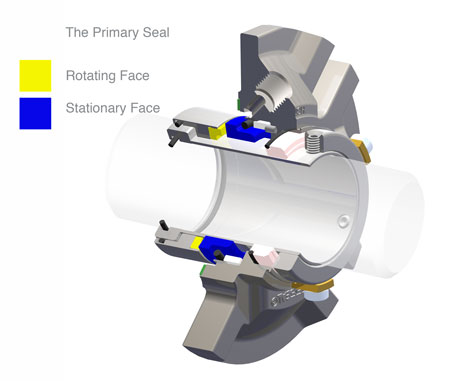
The primary seal is essentially a spring loaded vertical bearing - consisting of two extremely flat faces, one fixed, one rotating, running against each other. The seal faces are pushed together using a combination of hydraulic force from the sealed fluid and spring force from the seal design. In this way a seal is formed to prevent process leaking between the rotating (shaft) and stationary areas of the pump.
If the seal faces rotated against each other without some form of lubrication they would wear and quickly fail due to face friction and heat generation. For this reason some form of lubrication is required between the rotary and stationary seal face; this is known as the fluid film
In most mechanical seals the faces are kept lubricated by maintaining a thin film of fluid between the seal faces. This film can either come from the process fluid being pumped or from an external source.
The need for a fluid film between the faces presents a design challenge – allowing sufficient lubricant to flow between the seal faces without the seal leaking an unacceptable amount of process fluid, or allowing contaminants in between the faces that could damage the seal itself.
This is achieved by maintaining a precise gap between the faces that is large enough to allow in a small amounts of clean lubricating liquid but small enough to prevent contaminants from entering the gap between the seal faces.
The gap between the faces on a typical seal is as little as 1 micron – 75 times narrower than a human hair. Because the gap is so tiny, particles that would otherwise damage the seal faces are unable to enter, and the amount of liquid that leaks through this space is so small that it appears as vapor – around ½ a teaspoon a day on a typical application.
This micro-gap is maintained using springs and hydraulic force to push the seal faces together, while the pressure of the liquid between the faces (the fluid film) acts to push them apart.
Without the pressure pushing them apart the two seal faces would be in full contact, this is known as dry running and would lead to rapid seal failure.
Without the process pressure (and the force of the springs) pushing the faces together the seal faces would separate too far, and allow fluid to leak out.
Mechanical seal engineering focuses on increasing the longevity of the primary seal faces by ensuring a high quality of lubricating fluid, and by selecting appropriate seal face materials for the process being pumped.
When we talk about leakage we are referring to visible leakage of the seal. This is because as detailed above, a very thin fluid film holds the two seal faces apart from each other. By maintaining a micro-gap a leak path is created making it impossible for a mechanical seal to be totally leak free. What we can say, however, is that unlike gland packing, the amount of leakage on a mechanical seal should be so low as to be visually undetectable.

A question that comes up often is, “why should I use mechanical seals instead of packing when packing is cheaper?” There are some advantages that are obvious and easy to understand, and a number of others where the
Pump packing is the earliest form of pump sealing and is still a widely used sealing technique. Originally gland packing was made from old ropes and natural fibre products that were packed around the shaft physically stuffing the gap with
When packing fails it simply starts to leak more and so can be readjusted and tightened to reduce the leak with the pump remaining in service. Whereas mechanical seal failure can necessitate the shutdown of the pump. This is why pump packing
Correctly adjusted gland packing should be maintained with a leakage rate of approximately 1-drop per minute of sealed product per inch/25mm of outside diameter of shaft. On a 2.000”/50mm diameter shaft this equates to 2 drops/min or 100
These numbers are based on an ideal scenario and, as experience tells us, the leakage rates from packed glands are considerably higher than this, often by as much as 5-10 times.
Correctly designed, specified and fitted mechanical seals have no visible leakage and therefore no product loss. On the figures used above, if the product cost 50p/lt, reduction in leakage alone would pay for even an advanced
Depending on the type of product the waste disposal costs can be significantly higher that the initial cost of manufacture. Just looking at our own domestic water bills illustrates this. Even when only dealing with water sewage, charges are
Companies are also now under extreme pressure and constant observation on environmental issues Governments are constantly under national and global pressure to ensure that manufacturers accept the responsibility for the effects their products
have on the environment and companies themselves often have environmental targets to meet. Leakage is becoming less and less acceptable and conservation of resources is increasingly important.
Because correctly fitted mechanical seals have no visible leakage they therefore have no effluent disposal costs and provide substantial benefits to emissions reduction.
On average the majority of gland packing consumes 6 times more power than a balanced mechanical seal. Running rotating equipment with packing in the stuffing box is like driving your car with the hand brake on. Would this affect your fuel
consumption? Of course it would and so packed glands therefore greatly increase power costs. In some cases pumps can be made to run at a lower speed and efficiency, increasing costs still further.
The single major cause of bearing failure in rotating equipment is contamination of the lubrication. In a study conducted by Mobil Oil it was discovered that water contamination of 0.002% reduces the rated bearing life by almost
Packing leaks by design and is in close proximity with the bearings. This subjects the bearings to a constant stream of leakage and contamination. Any reduction in contamination will greatly increase the Mean Time Between Failure (MTBF), and in
No leakage equates to longer bearing life and less downtime costs. Many mechanical seal failures are attributed to excessive shaft movement caused by failed bearings.
Most rotating equipment is fitted with repairable wear sleeves in the region of the gland packing to adress the fact that packing is designed to wear the shaft in this area. If a replaceable sleeve were not fitted, the shaft would need to be
If a separate wear sleeve is fitted there is the cost of holding a spare in stock but there is an underlying danger that the shaft diameter under the sleeve has been greatly reduced to allow for fitting, considerably reducing the shafts
Broken shafts are not uncommon and are generally caused by fatigue due to the constant bending of the shaft under operation. How does this happen? Running the pump away from its Best Efficiency Point, against throttled or closed discharge
Gland packing often requires the supply of a clean flushing medium to the lantern ring. This was originally done to prevent the ingress of air into a system under vacuum and was also found to cool the packing as it generated friction against
The costs here are the supply of the flush, the leakage of the flush to atmosphere and the dilution of the product itself. This dilution may be acceptable or costs may be incurred in the removal of the dilutant at a later stage in the process.
To ensure that packing operates as efficiently as it should it requires constant attention. Too loose and leakage rates are unacceptable, too tight and the packing can burn out on start up, increasing leakage, wear on the shaft or sleeve and
increasing power consumption. Packing is not simply just greasy rope but it is often treated as such. Maintenance must be constant and conscientious throughout the life of the packing to ensure acceptable operation.
Eliminating leakage reduces secondary maintenance costs by reducing corrosion, cleaning and painting. Secondary maintenance costs would be greatly reduced.
Packing leaks, as it is designed to and it leaks the “sealed” product to atmosphere. As we have already agreed this is becoming more and more unacceptable for environmental reasons, especially if the product is corrosive, toxic or
All products classified by fugitive emission or hazardous should be double sealed. Airborne pollution is greatly reduced; double seals can achieve zero product emissions.

Long ago, companies didn’t want to switch to mechanical seals because of the complicated installation and need to completely disassemble the equipment. The invention of cartridge and split mechanical seals effectively eliminated those dilemmas, but many operations have stayed with pump packing out of sheer habit in situations in which seals would provide a better return.
Likewise, some customers will try to make a mechanical seal fit into an application where packing makes more sense. In this post, we’ll provide information on making the best sealing choice based on operational priorities, applications, and budget.
For many types of equipment, applications, or conditions, using a mechanical seal is really the only effective sealing option. This decision focuses on the safety or environmental issues associated with leakage.
A mechanical seal, and more specifically a double mechanical seal, should always be used when the pumped fluid presents a safety, health, or environmental hazard. Packing cannot be 100% leak free. Even when leakage isn’t visible, harmful vapors could be escaping. This is also true for single mechanical seals.
If reliability is a primary factor, the clear choice is mechanical seals. And although the initial investment is considerably higher than pump packing, it will pay off long term. The decision to go with a mechanical seal comes with a level of commitment to achieve a true return-on-investment. A good seal vendor will help you select the correct seal design, make sure you have the most effective installation/support setup for the conditions, ensure that the equipment is in the proper condition to support the mechanical seal, and outline the regular maintenance schedule (topics we will covering in upcoming blogs). These commitments will ensure that the seal investment will pay off for many years.
Leakage/Loss of Valued ProductWhile compression packing doesn’t necessarily need to leak, typically there will be some leakage. Depending on the application and the fluid being sealed, this may be considerable. And due to the typically lower lifespan of packing, the leakage associated with failure will occur more frequently. In some instances, this is not an issue. However, it is often a safety issue due to the type of product or the volume of leakage (and/or lack of maintenance staff to routinely clean up the mess).In some cases, our customers find that the savings in lost product actually pays for the cost of the new mechanical seal very quickly. We recommend measuring the loss of product for a single pump for a week (including the clean-up maintenance labor)…then calculating for the year, multiplied by similar pumps across your operation. The results are often eye-opening and often make for an easy return-on-investment conclusion for moving to mechanical seals.
The decision to move to mechanical seals is often driven by the impact of constant leakage from packing on the shaft; bearings; safety; and maintenance.
Maintenance SupportPacking requires more labor to routinely adjust and repack as well as the frequent leakage cleanup noted above. Is your organization adequately staffed? This, too, may be a deciding factor.
Stuffing Box AccessibilityBecause packing will wear over time and require gland adjustments, the stuffing box must be accessible to maintain the packing.
Product Contamination/DilutionSince many sealing applications require the packing to include a flush to cool, the cost to remove the flush water or the possible contamination may be an issue in some applications.
Premature Bearing FailureMaintenance staffs often use a water hose to rinse leaking product away from base plates, and the excess moisture from failed packing can wreak havoc with bearings.
Sleeve damage is a frequent occurrence and costly— not only because of the sleeve cost, but also the expense involved in the sleeve removal. Packing removal almost always means changing the bearings and wear rings. Many parts also get broken or lost when pumps are disassembled.
In many cases, compression packing IS still the right answer for rotating equipment applications. When the factors above are not an issue and adequate staff is available for adjustments and repacking, packing offers a low up-front cost and fairly simple maintenance. And although some say that packing requires more energy than mechanical seals, our testing has found that they are essentially the same.
Cost: Packing provides a lower up-front cost than mechanical seals. The benefit of the mechanical seal has to outweigh this cost. This can be more difficult when the equipment is large, or requires more costly metals and elastomers.
Ease of installation/Turnaround time: Installation of packing rings does not require decoupling of drive shaft unlike in case of installing the non-split mechanical seals. This leads to a relatively easier installation and shorter turnaround time.
Equipment condition: Mechanical seals typically require equipment to be in good condition to operate reliably. This includes shaft finish, pump/driver alignment, cavitation, and vibration.
Radial/axial motion and misalignment:Most mechanical seals tolerate very little radial movement or misalignment, and little to no axial movement. If the shaft is often moved axially, such as with many paper refiners, packing is often the only option available. While these issues can sometimes be addressed with the right choice of mechanical seal and support system, packing is typically the optimal choice.
One area where these factors align is in large slurry pumps, such as those found in the mining and ore processing industry. Though mechanical seals will provide an excellent seal for some of this equipment, the confluence of the expense due to large equipment size, large shaft movements due to large particles impacting the impeller, and abrasive media leads to most customers choosing to pack their equipment.
Today’s packing advances also mean that packing will last longer in many situations and require fewer adjustments than the basic options available in the past. New materials such as carbon fiber, advanced lubricants, and new braiding technology translate to longer packing life and fewer maintenance and equipment wear issues. Learn about these different technology advances in an upcoming post.
Raman Hanjra is Global Product Line Manager of Packing & Gaskets for A.W. Chesterton Company. He holds a BS in Mechanical Engineering and an MBA in Product & Market Development and Supply Chain Management. He started his career as a sales engineer for mechanical seals and has held various sales, marketing and product leadership positions globally. In his free time, Raman enjoys photography, golf, and reading about international trade and macroeconomics.
This website is using a security service to protect itself from online attacks. The action you just performed triggered the security solution. There are several actions that could trigger this block including submitting a certain word or phrase, a SQL command or malformed data.

For hundreds of years, packing has been used to minimize leakage from pumps and rotating equipment. As rotating equipment has evolved, however, so has the need to minimize that leakage even further.
Without some sort of sealing mechanism, process fluid easily leaks out of pumps through the gap surrounding the shaft as it enters the pump housing. For years, pump packing has been used to reduce leakage and minimize the space or clearance between the shaft and pump housing.
The very first patents for mechanical seals appeared in the early 1900s. Since that time, a wide range of seal technology has emerged, ensuring there’s a seal for nearly any application.
There are perks to both mechanical seals and pump packing, so which is right for the application at hand? In this post, we’ll discuss the pros and cons of each.
Compression packing is cut to length, formed in rings, and installed in the pump’s stuffing box. The rings are mechanically compressed to reduce leakage.
When the pump is running, liquid enters the stuffing box under hydraulic pressure. The liquid flows under the packing rings and eventually makes its way out of the packing gland. If the packing leaks too much, it can be tightened by the operator or mechanic. Note that the packing’s job is to reduce leakage. Not prevent it entirely.
Pump packing is an inexpensive method of sealing pumps and installs easily. Operators and maintenance teams must determine, however, if these benefits outweigh the disadvantages of packing.
Over time, packing wears and loses material causing it to leak more than desired. A mechanic or operator must tighten the packing gland again. Adjustments are made frequently and have no set degree of tightening.
Because of this, mistakes are easily made and packing glands are often over-tightened. Over-tightened packing glands oftentimes shorten packing life as the packing overheats and rapidly deteriorates.
Improper packing of the stuffing box can cause rotating equipment to consume more power than mechanically sealed equipment as it works to overcome the friction imparted by packing. Learn more about packing installation in our post "Terms You Need To Know For Packing Installation in Centrifugal Pumps".
Packed pumps and rotating equipment require more maintenance resources as well. This equipment is down more often than mechanically-sealed equipment due to corrosion problems, bearing failures, and shaft sleeve replacements.
Though the packing itself is less expensive than mechanical seals initially, there are other costs associated with this sealing method. Those costs include housekeeping, product loss, and additional power consumption.
Alternatively, mechanical sealing methods can provide many benefits over pump packing. There are many options for mechanical sealing. Single seals are the most common.
Mechanical seals consist of two flat surfaces (materials could include tungsten carbide, silicon carbide, or carbon graphite) compressed by a spring against each other. Just like packing, mechanical seals also require a small amount of leakage. However, the leakage is small, or not noticeable at all.
The pumped product generates a light film of fluid between the seal faces. The film prevents the faces from touching, lubricating them, and absorbing the heat generated from the associated friction. The fluid crosses the seal face as a liquid, then vaporizes into the atmosphere. Single mechanical seals are common practice when the pumped product poses little to no risk to the environment.
Like pump packing, the mechanical seal does leak. But unlike pump packing, in many applications the leakage is so small it’s practically invisible. This means there’s no mess on the floor to cause potential safety hazards. With less leakage, there’s less product loss.
One disadvantage to mechanical seals is the complexity involved with the installation. Proper installation is critical to the long-term success of the seal so it’s important that they’re installed by trained professionals. Check out this blog post we wrote about mechanical seal installation, “5 Ways to Kill A Mechanical Seal During Installation”.
Although mechanical seals require a higher initial dollar investment, when properly applied, they can run for over 10 years without failure or adjustment. When considering the cost of replacing and maintaining packing, installing a mechanical seal will cost less than pump packing over the lifetime of the equipment.
The biggest advantage to mechanical seals over pump packing is the minimal amount of maintenance. Packing requires frequent adjustment and replacement, not to mention the upkeep that comes with constant leaking.
On the flip side, the upfront cost is substantially higher for a mechanical seal over braided packing or other types of packing. Teams must decide for themselves if the maintenance required to properly care for packed rotating equipment is sustainable.
If it’s decided to look into replacing packing with mechanical seals, get an engineer involved to help select the right seal for the application. Seals can be expensive and with hundreds of options to choose from, it’s best to lean on the expertise of someone who frequently selects them.
Need help selecting the right mechanical seal for your process? Ask us about it! We gladly provide technical expertise to manufacturers and municipalities in Wisconsin, Minnesota, and upper Michigan.
www.watertechonline.com is using a security service for protection against online attacks. An action has triggered the service and blocked your request.
Please try again in a few minutes. If the issue persist, please contact the site owner for further assistance. Reference ID IP Address Date and Time 6870f9dd02577cf1d26e6b817a4a4553 63.210.148.230 03/04/2023 05:29 AM UTC

Modern pumps, compressors, mixers, agitators and other rotary shaft equipment are assembled using either compression pump packing or mechanical seals to minimize emissions and fluid.
Compression pump packing controls leakage whereas mechanical seals will tend to stop any visible leakage all together, keeping work environment clean and hazard free.
Compared to compression packing the initial cost of a mechanical seal is high, however overtime, the associated cost accrued by using compression packing, for example power consumption, maintenance and downtime, could be far in excess of the initial cost of a mechanical seal, which works unattended for a long time.
After completing a recent training class, I had opportunity to ask our customer what were some of the highest cost failures they experienced. The answer? Mechanical seal failures. Mechanical seals come in a wide variety of configurations and manufacturers. The cost of these seals can range from $1000 to $3000 per inch of shaft diameter. These are very close tolerance and will not withstand misalignment for long if at all. A high percentage of mechanical seal failures are due to vibration induced by misalignment.
While researching several mechanical seal manufacturers to gain some insight as to what their tolerances were (they are specific to configuration and are provided with the mechanical seal), I ran across the following very good article on mechanical seal basics.
Years ago, most pump shafts were sealed using rings of soft packing, compressed by a packing gland, but this type of shaft seal required a fair amount of leakage just to lubricate the packing and keep it cool. Then came the development of the “mechanical seal,” which accomplishes the job of restraining product leakage around the pump shaft with two very flat surfaces (one stationary and one rotating). Even though these mechanical seal faces also require some (very small) leakage across the faces, to form a hydrodynamic film, this leakage normally evaporates and is not noticeable. Most pump shafts today are sealed by means of mechanical seals. However, because of the delicate components used for this new sealing method, mechanical seal failures are the greatest cause of pump down time. This begs for a better understanding of this seal type and its application.
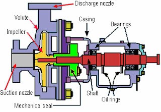
Mechanical seals are leakage control devices, which are found on rotating equipment such as pumps and mixers to prevent the leakage of liquids and gases from escaping into the environment. Figure 1 above shows a typical centrifugal pump, which highlights its constituent parts, including the mechanical seal.
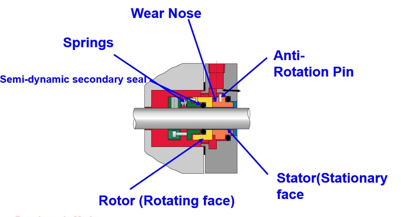
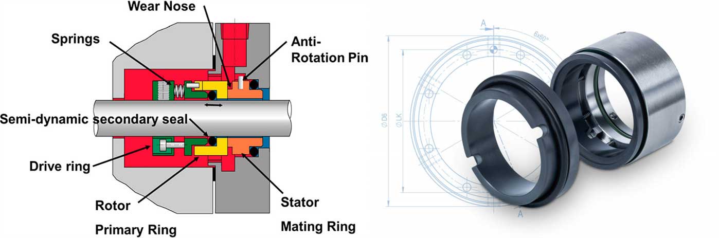
A mechanical seal consists of 2 principle components. One component is stationary and the other rotates against it to achieve a seal (Figure 2). There are many types of mechanical seal, ranging from simple single spring designs to considerably more complex cartridge seal types. The design, arrangement and materials of construction are essentially determined by the pressure, temperature, speed of rotation and product being sealed (the product media).
III. The seal between the rotating member and shaft or shaft sleeve (4). This is known as the secondary seal and may be an o -ring as shown, a v -ring, a wedge or any similar sealing ring.
3 of the 4 main sealing points need little explanation, but consideration is required for the sealing point between the rotating and stationary components (faces). This primary seal is the basis of a mechanical seal design, and is what makes it work. The rotating component (3) and stationary component (1) are pressed against each other, usually by means of spring force.The mating faces of both components are precision machined (lapped) to be extremely flat within 2 light bands, which is an optical method of measuring flatness).
This flatness minimizes leakage to a degree where it is essentially negligible. In fact, there is leakage between these faces but it is minute and appears as a vapor. (For immediate consideration)
Spring compression (usually) provides initial face pressure. This pressure is maintained when the seal is at rest via the spring(s) thus preventing leakage between the faces
If the mechanical seal faces rotated against each other without some form of lubrication they would wear out (and the seal would fail) due to face friction and the resultant heat generated. So, lubrication is required which for simplicity, is supplied by the product media. This is known as fluid film and maintaining its stability is of prime importance if the seal is to provide satisfactory and reliable service.
The primary disadvantage of this seal type is that it is prone to secondary seal hang-up and fretting of the shaft or sleeve, especially when the seal is exposed to solids. A pusher seal type should not be selected if the secondary seal is likely to hang-up. Can small deposits of solids form ahead of the secondary sealing member?
There are multiple designs available for the mechanical seal configuration. Understanding how they work will help the readers select the appropriate type for their application.
NON-PUSHER OR BELLOWS SEAL does not have a secondary seal that must move along the shaft or sleeve to maintain seal face contact. In a non-pusher seal the secondary seal is in a static state at all times, even when the pump is in operation. A secondary sealing member is not required to make up the travel as the rotary and stationary seal faces wear. Primary seal face wear is typically accommodated by welded metal or elastomeric bellows which move to assist in the compression of the rotary to stationary seal faces.
The advantages of this seal type are the ability to handle high and low temperature applications (metal bellows), and that it does not require a rotating secondary seal, which means it is not prone to secondary seal hang-up or shaft/sleeve fretting. Elastomeric bellows seals are commonly used for water applications.
The disadvantages are that thin bellows cross sections must be upgraded for use in corrosive environments, plus the higher cost of metal bellows seals.
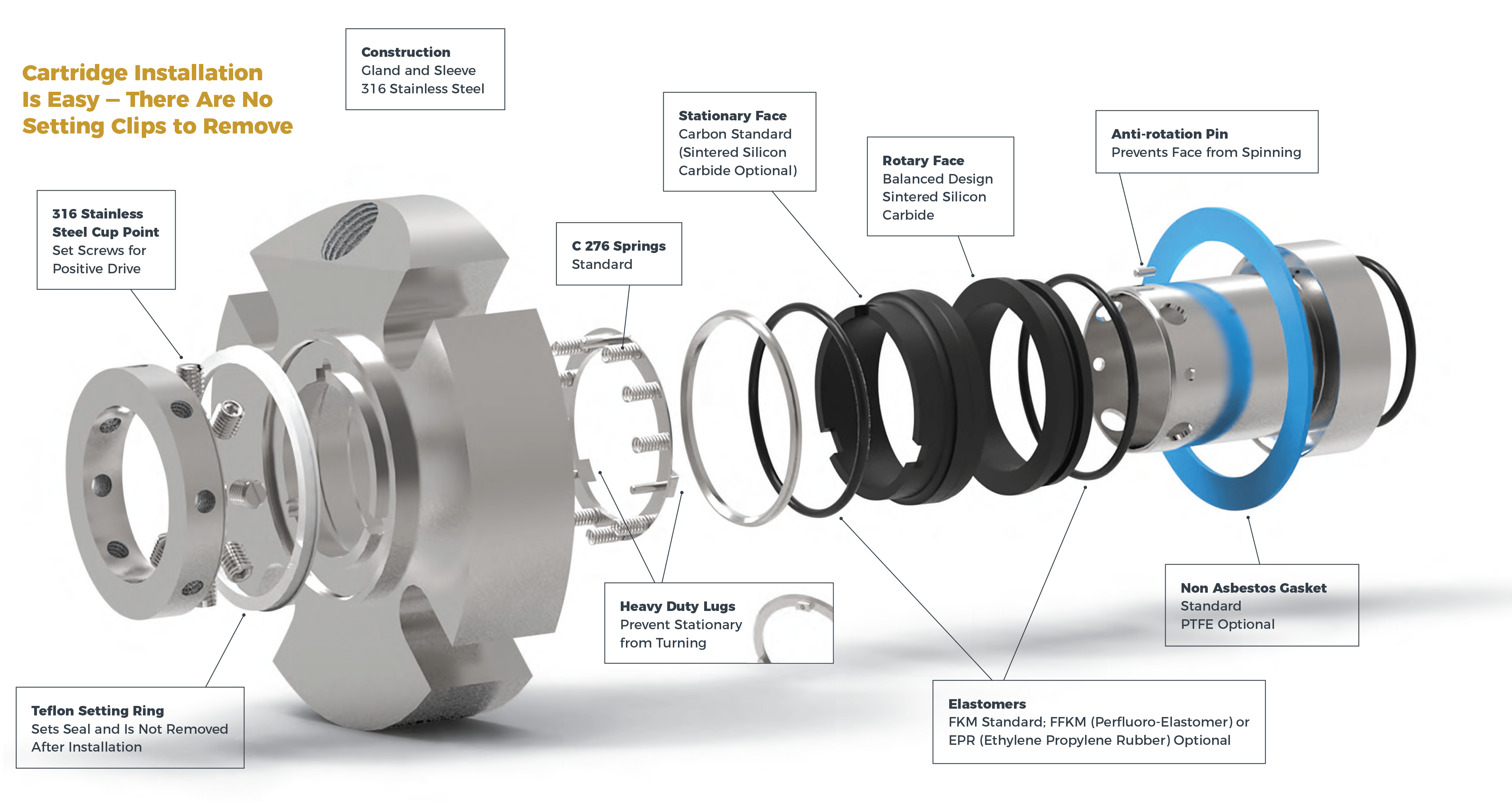
CARTRIDGE SEALS have the mechanical seal pre-mounted on a sleeve (including the gland). They fit directly over the shaft or shaft sleeve, and are available in single, double, and tandem configurations. Best of class pump users give strong consideration to the use of cartridge seals.
The advantages are that this seal configuration eliminates the requirement for seal setting measurements at installation. Cartridge seals lower maintenance costs and reduce seal setting errors.
Single seals do not always meet the shaft sealing requirements of today’s pumps, due to the small amount of required leakage when handling toxic or hazardous liquids; suspended abrasives or corrosives in the pumpage getting between the seal faces and causing premature wear; and/or the potential for dry operation of the seal faces. To address these situations, the seal industry has developed configurations which incorporate two sets of sealing faces, with a clean barrier fluid injected between these two sets of seal faces. The decision to choose between a double or single seal comes down to the initial cost to purchase the seal vs. the cost of operation, maintenance and downtime caused by the seal, plus the environmental and user plant emission standards for leakage from the seal.
The more common multiple seal configuration is called a Double (dual pressurized) seal, where the two seal face sets are oriented in opposite directions. The features of this seal arrangement are:
The metal inner seal parts are never exposed to the liquid product being pumped, which means no need for expensive metallurgy; especially good for viscous, abrasive, or thermosetting liquids.
The other multiple seal configuration is called a Tandem (dual unpressurized) arrangement, where the two individual seals are positioned in the same direction. This seal arrangement is commonly used in Submersible wastewater pumps, between the pump and motor, with oil as the barrier liquid. The typical features of this seal arrangement are:
The proper selection of a mechanical seal can be made only if the full operating conditions are known. Identification of the exact liquid to be handled is the first step in seal selection.
For best results with double (or tandem) seals handling abrasive, the inboard seal faces should be a hard material, such as silicon carbide vs. silicon carbide, while the outboard seal faces should have maximum lubricity, such as silicon carbide vs. carbon graphite.
The seal type and arrangement selected must meet the desired reliability, life cycle costs, and emission standards for the pump application. Double seals and double gas barrier seals are becoming the seals of choice. Finally, it should be noted that there are special single seal housing designs that greatly minimize the abrasives reaching the seal faces, even without an external water flush, but this is a subject for another column.


 8613371530291