
centrifugal pump mechanical seal free sample

1. Lepu Seal has been tested in all aspects. It has been detected in terms of insulation resistance, current leakage, and current load. Lepu ensures that the product quality and appearance are same to the original
2. Lepu Seal is strong enough to meet the technical needs of centrifugal pump mechanical seal animation market. Lepu seal is 100% replacement as original
3. In a flock of , centrifugal pump mechanical seal animation has many excellent properties such as [拓展关键词. Equipped with professional operation system, Lepu seal"s quality is ensured
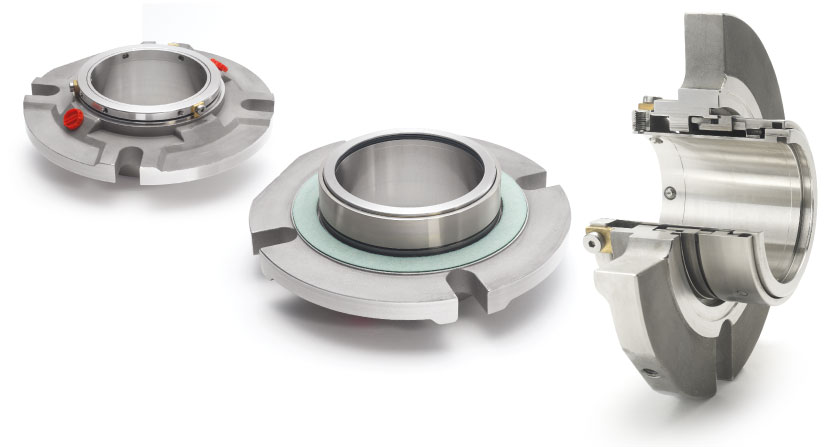
4. Compared with the other similar products, centrifugal pump mechanical seal animation exhibited features like . The seal face uses high quality SSIC for stationary and rotary
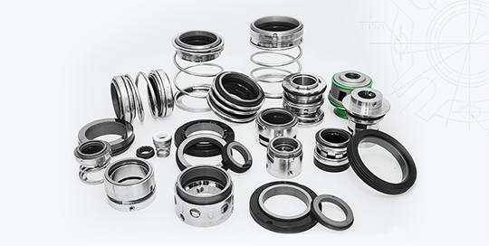
5. centrifugal pump mechanical seal animation are usually , so it"s types of mechanical seals for pumps to give them a try. Lepu products cost less than that of the original
1.Blackmer mechanical seal 45mm is structural simple and reliable. It has a wide application scope.2. Mechanical seal 55mm is suitable for CNP pumps, often used for stainless steel vertical mulltistage centrifugal pump.3.Blackmer mechanical seal also can provide important material certifications available.
We focus on manufacturing mechanical seal and seal spare parts in the past 20 years.Lepuseal was founded in 1998, located in Guangzhou, China. now lepuseal is one of the leading mechanical seal manufacturer in china, and maybe the best cartridge mechanical seal manufacturer in south of China.
Lepuseal have more than20 years experienceinmanufacturing mechanical seal, we established astrong technology team include 20+ engineerR&D team, more than 150 skilled workers team, more than 10 person quality control team, that help us to provide strong technology support to our users.
Lepuseal have more than10000 square meters workshop and60+ advanced CNC machineto provide strong ability for production.And make sure we can offer fast delivery service to our clients.
1. Over the years, Guangzhou Lepu Machinery CO., LTD has achieved stable development for its centrifugal pump mechanical seal animation . We have a team specializing in product development. Their expertise enhances the planning of product optimization and process design. They effectively coordinate and implement our production.
A dry gas seal is a revolutionary way of sealing machines and protecting them from dust, moisture and other contaminants. A dry gas seal is a sealing device that uses pressurized gas to keep two surfaces from touching. The most common type of dry gas seal is the O-ring, which is used in many applications, including mechanical seals, piston rings, and gaskets. Dry gas seals are also used in many other industries, such as the food and beverage industry, where they are used to seal containers and prevent contamination. This type of seal not only helps to keep the machine running with maximum efficiency but also significantly reduce downtime, making it cost-effective in the long run. In this article, we"ll explore what a dry gas seal is, how it works and why you should consider using it for your machinery. By understanding the benefits of a dry gas seal and its uses, you can make an informed decision about the best sealing system for your needs. How does a dry gas seal work?Dry gas seals work by using a series of labyrinths to separate the high pressure seal gas from the atmosphere. The labyrinths are formed by a series of grooves and ridges on the surface of the seal ring. The seal ring is rotated at high speed, causing the gas to flow through the labyrinths. The gas is then forced through an aperture in the center of the seal ring, where it escapes into the atmosphere. What is a dry gas seal used for?Dry gas seals are used on rotating equipment to help minimize the leakage of high pressure gases from the inside of the machinery. This helps to reduce maintenance costs and improve safety. Dry gas seals are commonly used in applications such as pumps, compressors, turbines, and blowers. Advantages of a dry gas sealThere are many advantages of a dry gas mechanical seal. One advantage is that they are much simpler in design than other types of seals, making them more reliable and easier to maintain. Additionally, dry gas seals do not require the use of any lubricating fluids, which can leak or evaporate over time. This makes them more environmentally friendly and cost-effective in the long run. Finally, dry gas seals have a much longer lifespan than other types of seals, meaning that they need to be replaced less often.Disadvantages of a dry gas sealThere are several disadvantages of dry gas seals, including: - they can be expensive to purchase and install- they require careful maintenance and regular inspection- they can be susceptible to wear and tear- they can leak if not maintained properlyHow to choose the right dry gas seal for your applicationThere are a few key factors to consider when choosing the right dry gas mechanical seal for your application. The most important factor is the type of fluid being sealed. Gas seals are designed to seal either liquids or gases, but not both. Make sure to choose a gas seal that is compatible with the fluid you are sealing.Another important factor to consider is the pressure of the fluid being sealed. Gas seals are rated for different maximum pressures, so make sure to choose one that can handle the pressure of your application.Finally, take into account the size and shape of the sealing surfaces. Gas seals come in a variety of sizes and shapes to fit different applications, so make sure to choose one that will fit your needs.ConclusionDry gas seals are an extremely important component for many industrial operations, and their ability to prevent leaks has made them invaluable in a variety of applications. Understanding the basics of how dry gas mechanical seal work and how they can be used effectively is helpful when considering the various options available for any specific application. With the right choice, dry gas seals can provide reliable, leak-free performance which will save time, money and resources while ensuring safety and reliability. Lepu dry gas seal manufacturer provides best quality flowserve dry gas seal and dry gas seal. Welcome to contact us!

MINKIX is a professional mechanical seal company that provides all kinds of inventory mechanical shaft seals for pumps, along with the same-day dispatch, and assures the aftermarket of higher quality, precision and performance.
We pride ourselves on being the in-stock supplier of mechanical seals that uses ERP to manage inventory. By doing so we are ensuring our clients are getting the right mechanical seals in the fastest manner possible.
With years of commitment to manufacturing quality seals and providing an excellent customer service, MINKIX is growing and gaining reputation and trust among wholesalers, distributors, and repair businesses.

Mechanical seal pumps provided by The Titus Company provide many benefits over traditional magnetic drive pumps, particularly in industries working with slightly dirty liquids. These pumps are ideal for moving liquids contaminated by suspended particles. The liquids going through CDR Pompe pumps should be low viscosity and clean or only slightly dirty. You’re likely to find them in industries that complete chemical processes, such as pharmaceuticals, wastewater treatment and fertilizer production.
The CCL-B Series uses a standard motor and close-couple execution to function properly. One distinction is the Plastic Lined Horizontal Single Stage Centrifugal Pump, which can complete both closed- and long-coupled processes.
The CCL/CCL-B Series provides many unique benefits to users. Take a look at the parts that make up the whole, and you’ll understand why CDR Pompe centrifugal pumps are excellent for heavy duty operations.
The lined shaft sleeve uses a mechanical CSE seal design to prevent the metallic parts of the sleeve from coming into contact with any fluids in the pump. While it generally uses the standard PP lining in these models, it also accommodates other materials, like Hastelloy C.
Another benefit of this separation is that you can feel more secure about the connection and seal created between the two. You have to push the lined shaft sleeve into position manually. As you do, the sleeve will push the O-ring against your impeller, providing a tight seal that lasts even if the pump itself fails. And, once fitted, the sleeve will synchronize with the shaft and the impeller, keeping all parts together even when the pump rotates in the opposite direction.
The pump’s casing is made of ductile iron. In addition to making the pump vacuum-resistant, it also absorbs straining, external shocks and vibrations to prevent damage to the device itself. It is self-venting.
The seal chamber keeps solid particles and slurry from contacting the seal, which can affect the pump’s efficiency. This chamber is wide and conical to ensure the entire seal is protected. It can handle all venting, flushing and draining operations.
Ensuring you have the proper seal for whatever fluids you’re pumping is essential to prevent dangerous leaks and optimize productivity. For example, clean fluid requires a TSI single internal seal, while corrosive fluids prefer a TSE single external seal. Dirty and aggressive fluids need a CSE single internal seal. For the most dangerous fluids, you will need a double tandem seal for the best chance against leakage.
TSI/TSI Double Tandem Mechanical Seal: For PLAN 53A/54. Ideal in situations where the media is dirty, unstable and unable to be released into the air.
CSE-Q Single Internal Mechanical Seal With Quench: For PLAN 62, when necessary (after liquid crystallization). Provides options for working with corrosive, abrasive, dirty liquids. It has one of the simplest maintenance needs due to a semi-cartridge construction.
Made with 400 series stainless steel, this shaft offers no leakage points and less than .05 mm shaft deflation. A long screw provides balance and rigidity as it connects the shaft to the impeller. Both the materials and its construction ensure the shaft will have a long, reliable life free of corrosion while improving the seal’s life.
The key-driven system for their Transfer Molding impeller eliminates the common start-up reverse rotation error and lets your pump get right to work. The sold metal configuration provides high chemical resistance, and the back vanes are ideal for the life span of the impeller, seal and bearing.
These versatile pumps have a use in all kinds of industries. It’s suitable for handling hazardous materials that could be aggressive or corrosive, such as what you may find in fertilizer processing and other farming operations, fuel mining, treatment of water and air and RAEE or the recovery of precious metals.
CDR Pompe pumps are equipped with durable, reliable parts designed to work with even extensive heavy-duty service. They’ve been specially manufactured to fit with the chemical industry’s growing standards, similar to the hydraulic manufacturing of the UCL Series.
The models in this series also utilize polypropylene-lined mechanical seals, as well as Polyvinylidene fluoride (PVDF) and Perfluoroalkoxy (PFA) lining. Because you have more options, you can cater these machines more specifically to your needs. Specifications include:
While much of the basics of the UCL/UCL-B Series match the manufacturing of the CCL/CCL-B Series, each part has a few distinct differences. Explore them closely so you can choose the pump model that most closely fits your industry’s pump needs.
Strong, ductile iron encases peripheral fluoroplastic pump areas to protect it from vibration, pipe strain and external shocks during handling and movement. It also makes the casing vacuum resistant. The casing is self-venting and, if your uses require it, an optional draining casing can come with it.
Transfer Molding took this sold metal impeller and made it even more durable and chemical-resistant by adding Fluopolymers lining consisting of PP, PFA and PVDF – a collection of sturdy polymers that avoid chemical reactions while enhancing the impeller’s reliability mechanically. Using a system that’s key-driven, you no longer have to think about reverse rotations on startup. And thick back vanes aid the bearings and seal, providing all parts with a longer life span.
Choose a seal chamber lined with your preference of material – you can choose between PFA, PP or PVDF. All seals use a broad, conical build that’s equipped with breaking ribs. All chambers are made to push slurry and solids out of the seal’s way, as they can interrupt the media flow.
With the seal’s conical design, it can fit nearly any mechanical seal type, including both CSS single seals and CDC double cartridge seals. By providing a wide range of operations, you can procure maximum flexibility for any operation, even in challenging conditions. You can also adapt it to fir a number of UCL pumps.
Conventional Double Seal – Cylindrical Seal Chamber External Flushed – ISO 12756 –EX DIN 24960: Works similar to the CDC Double Cartridge Seal, with the necessary strength to prevent hazardous materials from leaking into the surrounding atmosphere and the ability to pump abrasive and dirty media.
Single External Seal Tapered Seal Chamber: Suits PLAN 02. This seal comes in a variety of materials by many brands, so you can use whichever you’re most comfortable with. The model version includes single PTFE bellow seals, which work best as external mountings.
CDC Double Cartridge Seal Tapered Seal Chamber: Good for PLAN 53A-54. This seal is one of the strongest available, designed for operations where leakage is immediately dangerous, such as with toxic or flammable materials. Because it doesn’t need the media to lubricate it, it’s also a good choice for working with unstable, dirty and polymerizing media.
Double Cartridge Seal Tapered Seal Chamber:Ideal for PLAN 52-53-54. It works similarly to the conventional double seal, but with the better maintenance of the cartridge configuration.
Faces Sealed in Diamond SiC: An immensely durable diamond coating provides a longer service life with practically no wear. It also contributes significantly to energy-saving costs.
CSS Single Internal Seal Tapered Seal Chamber: Works will for PLAN 62, as it’s also available in CSS-Q. A semi-cartridge configuration makes maintenance a breeze, even after working with corrosive and moderately dirty media. The metal and media parts never come in contact with one another so it’s also resistant to abrasive materials.
This shaft is made from 400 series stainless steel, molded into a strong, rigid shaft that should provide less than .05 mm deflection of the shaft, providing a long, reliable seal life free of corrosion. The shaft is manufactured to ensure there are no weak points that could result in leakage of hazardous materials. It comes with a long screw that allows it to easily connect with the impeller.
This part is separated from the impeller, allowing for an easier replacement when the need arises. It also constrains the damage to only the sleeve so the impeller does not need to be replaced along with it. In the case where failure occurs, the pump should still maintain a secure seal, as the sleeve pushes the O-ring into the impeller and cannot be adjusted without removing the sleeve.
The shaft sleeve is essential in creating a proper seal in the pump, and with the push-in-position design of this sleeve, you can feel confident in the manual security of the pump. Any part that could touch the media is coated with PFA and SiC to prevent corrosion, but you can easily change the material if you prefer a different lining, like Hastelloy C. Should the pump move in the wrong rotation direction on starting, the sleeve synchronizes with the impeller and shaft, preventing the seal from loosening.
Shaft sleeve:As a modular design element, you can easily remove, repair and replace it without damaging the surrounding parts. This makes the pumps easier to use and cheaper to maintain over time.
Everything about the CDR Pompe UCL/UCL-B Series is created to be of the highest quality so it functions well in many applications for years to come. Explore some of the more technical features below to better understand why these pumps are modeled as they are.
You can use two different types of seal protection for this bearing bracket – the standard oil seal, or a non-contacting labyrinth seal. The latter option provides a constant level oiler and conditions monitoring if you so choose.
These bearings are designed to withstand 17,500 hours. That’s equal to over 729 days or nearly two years of straight pumping. You’ll find one tow of bearings on the frontal or impeller side of the pump and one pair of contact bearings on the rear side, sometimes called the motor side. Both configurations boast high axial load ratings.
Any metal surfaces on the pump are costed with three paint layers. These layers are high-performing and prevent corrosion and damage for as long as possible. The layers are:
The UCL/UCL-B Series is ready to handle your most aggressive, hazardous and corrosive materials with a low viscosity in any industry setting. With some of the most consistently durable bearing brackets on the market, you can be sure these pumps will perform even in heavy-duty operations.
The hydraulic design of these models focuses on catering to the needs of the chemical industry, and due to their stringent guidelines, the pumps will make an excellent choice for those working in these industries:
The Titus Company specializes in compressed air systems, including these pumps. We’ve spent more than 30 years installing, replacing, repairing and maintaining systems for businesses just like yours.

The need for a leak-free pump became urgent in the modern age when industrial pumps began handling hazardous liquids. In the case of a toxic or flammable liquid, it is essential to protect both people and the environment from any leaks. Also, every leak means wasted product, which becomes significant when pumping expensive media, such as pharmaceutical materials.
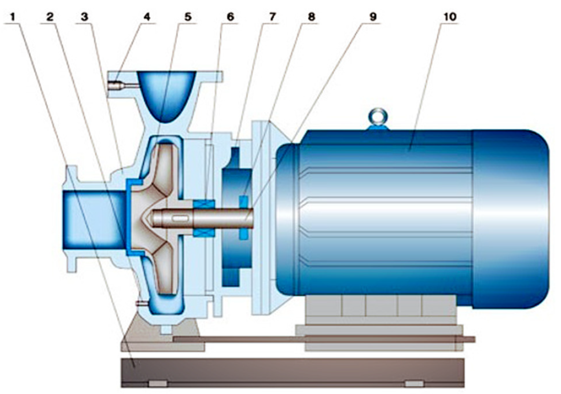
Consider why it is so challenging to prevent pumps from leaking. Take the common centrifugal pump as an example. In this pump, a shaft and impeller are rotated by a motor, but the motor is located outside the pump. It is where the shaft exits the pump, specifically at the points of contact between the rotating and stationary parts, that leaks can and do occur.
The stuffing box is a chamber situated on the outside of the pump case where the shaft exits. Within it, sealing material—a soft packing substance—is laid around the shaft.
Using a special device (a nut in the simplest case), the packing is then compressed, causing it to press against the walls of the chamber and the shaft, thus preventing liquid from flowing out of the pump.
However, the shaft has to be in close contact with the packing material in order for the seal to be tight. This can create friction and lead to a shortened service life.
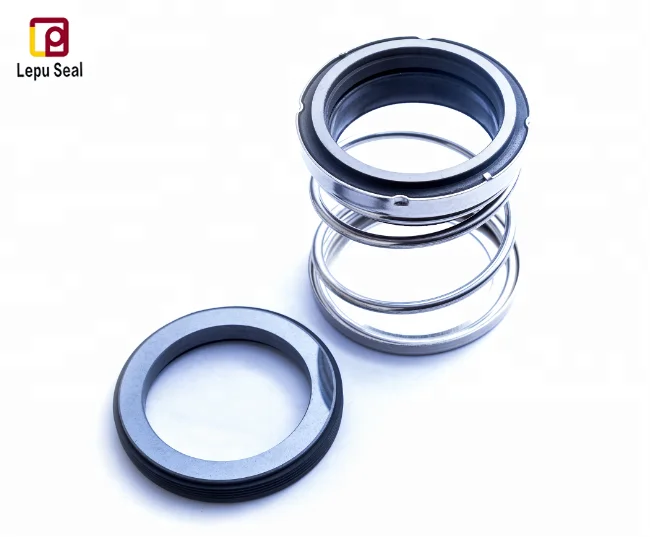
The main elements of mechanical seals are two rings: a moving one, which rotates with the shaft, and a stationary one, which is attached to the pump body with a pin.
Tightness against leaks is created by contact between the ring surfaces, which forms a so-called friction pair. To provide the contact, the moving ring is pressed against the fixed ring by a spring, spring unit or bellows—which is an elastic single-layer or multilayer corrugated sheath made of metallic, nonmetallic and composite materials. For additional sealing, secondary seals are used, which are O-rings made of elastomer.
Choosing the right seal ring materials is not a trivial task. The rings need to have sufficient strength and wear resistance to withstand the effects of pump operation and be chemically resistant to the pumped medium. In addition, they must be able to withstand the high temperatures that arise due to friction. For these reasons, friction pairs are surprisingly sophisticated technologies, requiring the theoretical and calculation disciplines of mechanics, thermodynamics, hydraulics and tribology. Due to the small clearance between the rings, the manufacture of modern mechanical seals actually falls into the category of nanotechnology.
Single friction pair mechanical seals may only minimize leaks, not eliminate them. To further attempt to eliminate leaks, double mechanical butt seals were created. The auxiliary system—called a flushing plan or piping plan—feeds a special fluid, called a barrier, to the area of the seal between the two rings of the friction pair. Its pressure is held a bit higher than that of the pumped medium in the sealing area and, in this way, tightness is achieved. The barrier fluid also performs the necessary tasks of heat removal and lubrication in the event that the pumped media lacks the properties to do so. Water, for example, loses its lubricating properties at about 176 F (80 C).
Mechanical double butt seals can eliminate leaks of the pumped fluid to atmosphere. However, they can be relatively expensive and difficult to maintain. In addition, even the most carefully constructed friction pair will fail in time due to wear, so they require continuous monitoring and replacement.
The principle of magnetic coupling is based on the transmission of torque from the driver to the impeller of the pump using permanent magnets made of rare earth metals (Image 3). The motor rotates the shaft with the driving magnets attached to it, which are located outside a sealed pump casing. The driven magnets are located inside the pump casing and are attached to the impeller. The movement of the driving magnets causes the driven magnets to rotate.
Due to this remote transmission of power, the shaft does not need to pass through the casing, so there are no holes and there can be no leaks. However, these pumps tend to be more expensive, due to the cost of the state-of-the-art magnets they require. Usually, these are made of exotic alloys of neodymium, cobalt and samarium, but neodymium iron boron (NdFeB) alloy is now considered more effective. The service life of these magnets can be tens, or even hundreds, of years—often longer than the service life of the pump itself.
The other advance that came about from the development of electromechanics and electromagnetic theory was the canned motor pump. This device combines the function of the electric motor with that of the classic centrifugal pump. It is similar to a pump with a magnetic coupling, but the role of the magnets is performed by the windings of the stator (fixed part of the electric motor) and the rotor. It is called “canned” because the motor is protected from short circuits by a special cylinder (shell) and located inside the pump casing in the pumped liquid, which simultaneously lubricates and cools the bearings.
Because canned motor pumps use fewer parts, they are compact. However, because the coils of the stator and the rotor are separated by several partitions, their efficiency can be relatively low. Therefore, these devices are ruggedly useful but do consume more power.
Persistent effort over many years has now produced a variety of options to achieve a leak-free pump. Each has its own mix of advantages and drawbacks. To determine which is best for your operation, specialists will select a design depending on the properties of the pumped liquids, operating conditions and economic constraints.
In order to understand centrifugal pump leakage, it’s important to first understand the basic operation of a centrifugal pump. As the flow enters through the impeller eye of the pump and up the impeller vanes, the fluid is at a lower pressure and low velocity. When the flow passes through the volute, the pressure increases and the velocity increases. The flow then exits through the discharge, at which point the pressure is high but the velocity slows. The flow that goes into the pump has to go out of the pump. The pump imparts head (or pressure), which means it increases the energy of the pump fluid.
Certain component failures of a centrifugal pump, such as coupling, hydraulic, static joints, and bearings, will cause the whole system to fail, but approximately sixty-nine percent of all pump failures result from the sealing device malfunctioning.
A mechanical seal is a device that is used to control leakage between a rotating shaft and a liquid- or gas-filled vessel. Its main responsibility is to control leakage. All seals leak—they have to in order to maintain a fluid film over the entire mechanical seal face. The leakage that comes out the atmospheric side is fairly low; the leakage in a Hydrocarbon, for example, is measured by a VOC meter in parts/million.
Before mechanical seals were developed, engineers typically sealed a pump with mechanical packing. Mechanical packing, a fibrous material usually impregnated with a lubricant such as graphite, was cut into sections and stuffed down what was called a “stuffing box.” A packing gland was then added to the backside in order to pack everything down. Since the packing is in direct contact with the shaft, it requires lubrication, but will still rob horsepower.
As with every pump, you’ll want to test your pump to discover the annual costs it requires to run. A packing pump may be affordable to install and maintain, but if you calculate how many gallons of water it consumes per minute or per year, you may be surprised by the cost. A mechanical seal pump could potentially save you a lot of annual costs.
If the centrifugal pump exhibits an uncontrolled leak, you must thoroughly check all potential causes to determine if you need repairs or a new installation.
Neglecting the Best Efficiency Point: Are you operating the pump at the Best Efficiency Point (BEP) on a performance curve? Each pump is designed with a specific Efficiency Point. When you operate the pump outside that region, you create problems with the flow that cause the system to fail.
Insufficient Net Positive Suction Head (NPSH): If you don’t have enough suction head to your pump, the rotating assembly can become unstable, cause cavitation, and result in a seal failure.
Operating Dead-Headed: If you set the control valve too low to throttle the pump, you can choke the flow. Choked flow causes recirculation within the pump, which generates heat and promotes a seal failure.
Dry Running & Improper Venting of Seal: A vertical pump is the most susceptible since the mechanical seal is positioned on top. If you have improper venting, air can get trapped around the seal and won’t be able to evacuate the stuffing box. The mechanical seal will soon fail if the pump continues to run in this condition.
Low Vapor Margin: These are flashing fluids; hot hydrocarbons will flash once exposed to atmospheric conditions. As the fluid film passes across the mechanical seal, it can flash at the atmospheric side and cause a failure. This failure often happens with boiler feed systems—hot water at 250-280ºF flash with the pressure drop across the seal faces.
Shaft misalignment, coupling imbalance, and impeller imbalance can all contribute to mechanical seal failures. In addition, after the pump is installed, if you have misaligned pipes bolted to it, you will impart a lot of strain on the pump. You also need to avoid a bad base: Is the base secure? Is it grouted properly? Do you have a soft foot? Is it bolted correctly? And last, check the bearings. If the tolerance of the bearings wears thin, the shafts will move and cause vibrations in the pump.
Do you have a good tribological (the study of friction) pair? Have you chosen the correct facing combinations? What about the seal face material quality? Are your materials appropriate for your specific application? Have you selected the proper secondary seals, such as gaskets and o-rings, that are prepared for chemical and heat attacks? Your springs should not be clogged or your bellows corroded. Last, keep an eye out for face distortions from pressure or heat, since a mechanical seal under great pressure will actually bow, and the skewed profile can cause a leak.
You need a proper seal flush arrangement, along with sufficient cooling. Dual systems have barrier fluids; the auxiliary seal pot needs to be in the right location, with the correct instrumentation and piping. You need to take the Length of Straight Pipe at Suction into account—some older pump systems that often came as a packaged skid include a 90º elbow at suction right before the flow enters the impeller eye. The elbow causes a turbulent flow that creates instabilities in the rotating assembly. All the suction/discharge and bypass piping needs to be engineered correctly as well, especially if some pipes have been repaired at some point over the years.
Other miscellaneous factors account for only about 8 percent of all failures. For example, auxiliary systems are sometimes required to provide an acceptable operating environment for a mechanical seal. For reference to dual systems, you need an auxiliary fluid to act as a barrier that prevents contamination or process fluid from spilling into the environment. However, for most users, addressing one of the first four categories will hold the solution they need.
Mechanical seals are a major factor in rotating equipment reliability. They’re responsible for leaks and failures of the system, but they also indicate problems that would eventually cause serious damage down the road. Seal reliability is greatly affected by the seal design and the operating environment.
Frank Rotello is mechanical seal reliability engineer for Cummins-Wagner. Cummins-Wagner Co., Inc. is a distributor for industrial and mechanical equipment covering the mid-Atlantic states with leading brands of compressors, pumps, and heat transfer equipment, and offer support services such as system design, assembly, and aftermarket service and repair. For more information, visit www.cummins-wagner.com.

From the operational point of view of centrifugal pumps, it becomes essential to correctly align the pump and the drive to ensure the mechanical seal functions properly. Attention shall be given to is nozzle loads. During the design as well as during the actual installation, the consideration of the nozzle loads is important. Higher nozzle loads beyond allowable values could lead to deformed casings and may be detrimental to mechanical seals due to rubbing of the shaft at the clearances. The sizing of the shaft in case of end suction pumps (and also the overhang) has to be controlled, which could result in excessive deflection at the mechanical seal faces.
When it comes to reliability of sealing the process liquid, a dual seal arrangement is the preferred choice. There are three arrangements defined in API 682: arrangement 1, 2, and 3. The arrangement 1 is the single seal arrangement. The arrangement 2 is the dual seal arrangement with unpressurized buffer liquid at the outboard seal. Finally, arrangement 3 is the dual seal arrangement with the pressurized barrier liquid at the outboard seals. With the barrier liquid being pressurized in arrangement 3, there is no leakage of process liquid to the atmosphere, and hence it is the most reliable option when it comes to applicability of stringent environmental norms from the point of view of the end user.
However, in order to ensure proper functioning and reliability of dual seals, the operational environment of the pump, piping, seal support system, and monitoring systems play a vital role. There are typically four API piping plans for seal support systems: API Plan 53 A, B, and C, and Plan 54.
All three variations of Plan 53 are similar from the point of view that they circulate the barrier fluid using the pumping screw inside the mechanical seal, but the methods of pressurizing the barrier fluids are different. Plan 53A uses direct pressurized nitrogen to pressurize ¬fluid in the reservoir. This plan is popularly used in most of the cases due to less complexity and also availability of nitrogen pressurizing source at site. However, to ensure reliability, one has to be careful about the absorption of nitrogen gas into the barrier ¬fluid. The amount of gas being absorbed is proportional to the pressure of the barrier system. The barrier ¬fluid with absorbed gas then reaches the seal faces due to circulation and at the ¬fluid film, due to depressurization, the gas may come out and hamper the seal performance. This is a reliability concern, and hence most of the seals with Plan 53A are limited to 10 bar (gauge) pressure. Plan 53B uses a bladder accumulator as a means of pressurization of barrier fluid. This overcomes the limitation of Plan 53A and the absorption of nitrogen into the barrier liquid, which limits the system pressure, which can be used in high pressure applications. The advantage of the Plan 53B is that it can be used in remote locations where the external source of pressurization is not available. The pressure of barrier liquid is maintained due to the expansion of the bladder inside the accumulator, which also enables the supply of make-up barrier liquid to compensate for a small amount of leakage of barrier -fluid. However, the monitoring of the liquid level in the reservoir is not possible, and as such, the sizing of accumulator considering the seal leakage and maintenance interval is critical. As the bladder expands to compensate for seal leakage, it needs to be refilled with barrier liquid. The usual cycle of refill is 25 to 28 days. Considering this as a basis, the size of the accumulator and the pre-charge pressure of nitrogen is estimated.
Plan 53C uses a piston as a means of pressurization of barrier ¬fluid inside the accumulator. The advantage of this design is that it uses the process fluid pressure from the seal chamber directly on the bottom side of the piston, whereas top side is exposed to the barrier liquid. The pressurization is achieved by the difference in the areas. The area exposed to process liquid is larger and is designed with ratios ranging from 1:1.1 to 1:1.25. As the seal chamber pressure is being used as a reference, the system itself takes care of process pressure fluctuations. However, as the piston is in direct contact with the process fluid, the material selection becomes essential. Also, the properties and quality of process ¬ fluid shall be carefully evaluated, it should not hinder the movement of the piston within the accumulator. Another important factor is the dynamic sealing of the process fluid from the barrier fluid. The failure of the piston seal will result in the equilibrium of pressures on both sides of piston, and because of the piston movement, friction and drag come into play. Thus, the plan is not so reliable for low pressure applications and recommended to be used in the applications with pressures greater than 7 bar (gauge).
Although a mechanical seal is a critical piece of equipment, it shall not be treated in isolation and due consideration should be given to the operating environment of the pump, seal support system, and most importantly, the perfect selection for the given application.
Abhijeet Keer is a design engineer who has been working in the fi eld with centrifugal pumps for over seven years. With strengths in mechanical construction and materials, he has gained valuable knowledge working in design with major players in pump industry, such as KSB Limited and Kirloskar Brothers Limited. He completed his Bachelor’s Degree in Mechanical Engineering from University of Mumbai, India. His professional experience covers new product design and developments, material selection and application engineering, and complete mechanical constructions.

A mechanical seal is simply a method of containing fluid within a vessel (typically pumps, mixers, etc.) where a rotating shaft passes through a stationary housing or occasionally, where the housing rotates around the shaft.
When sealing a centrifugal pump, the challenge is to allow a rotating shaft to enter the ‘wet’ area of the pump, without allowing large volumes of pressurized fluid to escape.
To address this challenge there needs to be a seal between the shaft and the pump housing that can contain the pressure of the process being pumped and withstand the friction caused by the shaft rotating.
Before examining how mechanical seals function it is important to understand other methods of forming this seal. One such method still widely used is Gland Packing.
Packing needs to press against the shaft in order to reduce leakage – this means that the pump needs more drive power to turn the shaft, wasting energy.
The stationary part of the seal is fitted to the pump housing with a static seal –this may be sealed with an o-ring or gasket clamped between the stationary part and the pump housing.
The rotary portion of the seal is sealed onto the shaft usually with an O ring. This sealing point can also be regarded as static as this part of the seal rotates with the shaft.
One part of the seal, either to static or rotary portion, is always resiliently mounted and spring loaded to accommodate any small shaft deflections, shaft movement due to bearing tolerances and out-of-perpendicular alignment due to manufacturing tolerances.
The primary seal is essentially a spring loaded vertical bearing - consisting of two extremely flat faces, one fixed, one rotating, running against each other. The seal faces are pushed together using a combination of hydraulic force from the sealed fluid and spring force from the seal design. In this way a seal is formed to prevent process leaking between the rotating (shaft) and stationary areas of the pump.
If the seal faces rotated against each other without some form of lubrication they would wear and quickly fail due to face friction and heat generation. For this reason some form of lubrication is required between the rotary and stationary seal face; this is known as the fluid film
In most mechanical seals the faces are kept lubricated by maintaining a thin film of fluid between the seal faces. This film can either come from the process fluid being pumped or from an external source.
The need for a fluid film between the faces presents a design challenge – allowing sufficient lubricant to flow between the seal faces without the seal leaking an unacceptable amount of process fluid, or allowing contaminants in between the faces that could damage the seal itself.
This is achieved by maintaining a precise gap between the faces that is large enough to allow in a small amounts of clean lubricating liquid but small enough to prevent contaminants from entering the gap between the seal faces.
The gap between the faces on a typical seal is as little as 1 micron – 75 times narrower than a human hair. Because the gap is so tiny, particles that would otherwise damage the seal faces are unable to enter, and the amount of liquid that leaks through this space is so small that it appears as vapor – around ½ a teaspoon a day on a typical application.
This micro-gap is maintained using springs and hydraulic force to push the seal faces together, while the pressure of the liquid between the faces (the fluid film) acts to push them apart.
Without the pressure pushing them apart the two seal faces would be in full contact, this is known as dry running and would lead to rapid seal failure.
Without the process pressure (and the force of the springs) pushing the faces together the seal faces would separate too far, and allow fluid to leak out.
Mechanical seal engineering focuses on increasing the longevity of the primary seal faces by ensuring a high quality of lubricating fluid, and by selecting appropriate seal face materials for the process being pumped.
When we talk about leakage we are referring to visible leakage of the seal. This is because as detailed above, a very thin fluid film holds the two seal faces apart from each other. By maintaining a micro-gap a leak path is created making it impossible for a mechanical seal to be totally leak free. What we can say, however, is that unlike gland packing, the amount of leakage on a mechanical seal should be so low as to be visually undetectable.

Approximately 88% of industrial process centrifugal pumps in the USA use mechanical seals which have been in commercial use since the 1920s. The concept of sealless magnetic drive centrifugal pumps has been around since the 1940s. In the past 30 years increased market demand for sealless pumps have driven pump manufacturers to continue to develop and evolve sealless pump designs. There are two primary types of sealless pumps; magnetic drive and canned motor pumps. This article will focus on magnetic drive pumps.
What key points should you consider in deciding whether your application is best suited for a pump with a mechanical seal or a magnetic drive sealless pump?
To determine what type of pump to use in a process plant it’s critical to understand not only the service conditions, but other factors that may be important to the user such as initial cost versus lifetime cost of ownership, spare parts commonality with existing pumps, etc. Certain applications are ideal for magnetic drive pumps, while others are definitely not appropriate for them. For example, applications with a high concentration of solids are inappropriate for magnetic drive pumps unless an external or filtered and recirculated flush is used. Services where the liquid will solidify in upset conditions or on shutdown which will plug the cooling/lubrication passageways inside the pump are also inappropriate for magnetic drive pumps.
Initial cost is a consideration although not necessarily the most important one in critical services. However in most cases it is very important to go beyond the initial cost. Single mechanical seal pumps typically have lower initial cost BUT a much higher cost over the life of the pump. A properly selected and operated mag-drive pump offers years of trouble-free service; some users have run magnetic drive pumps for decades with no maintenance whatsoever except for routine oil changes or motor bearing grease requirements. For this reason many pump users are slowly retiring all their mechanical seal pumps and replacing them with magnetic drive pumps.
To increase the reliability of a mechanical seal pump double mechanical seals can be used, however they are expensive and generally require an expensive and elaborate barrier fluid system which are a challenge to operate and maintain. Typically a double mechanical seal pump with a seal pot and auxiliary equipment will have a higher initial cost than a sealless magnetic drive pump which makes the choice of which type of pump to buy a no brainer.
Furthermore, a close-coupled configuration can be readily used on mag-drive pumps up to 40 hp, depending on the manufacturer. The close coupled configuration not only eliminates the coupling cost, but the need for motor/pump shaft alignment, which if not done correctly, can result in mechanical seal failures as well as ball bearing failures of the pump power frame and/or electric motor, both of which result in costly downtime. Additionally a close coupled pump package has a much smaller foot print than a long coupled pump, making mag-drive close coupled pumps ideal for applications where space is limited.
Mechanical seals are the weak point in a mechanical seal centrifugal pump whereas the internal ceramic inner magnet bearing system is the weak point for magnetic drive process pumps.
The process fluid is circulated within the magnetic drive pump to cool and lubricate the pump’s internal bearing system, just as the mechanical seal in a standard centrifugal pump is cooled and lubricated by the pumped fluid or an external flush. However, unlike a pump with a mechanical seal that allows the pumped fluid to escape the pump when it fails, the mag-drive pump’s bearings and the shaft that supports them are located within a hermetically sealed rear casing/containment shell, so that potential fluid leakage into the atmosphere in the event of a catastrophic failure is virtually eliminated.
Running any centrifugal pump dry will result in a failure. However, the failure mode is different for a pump with mechanical seals versus a magnetic drive pump. Mechanical seals require a small amount of liquid to pass across their faces to provide cooling and lubrication otherwise the seal will run dry and fail. A small amount of that liquid will escape the confines of the seal faces and leak into the atmosphere as either a liquid or vapor. This is why mechanical seal pumps must be monitored for fugitive emissions in VOC (volatile organic compounds) as well as toxic or noxious applications.
Magnetic drive pumps require internal circulation of the pumped liquid to cool and lubricate the ceramic bearing system that supports the inner magnet carrier. To prevent magnetic drive pump bearing systems from running dry many manufacturers recommend a simple power monitoring device that shuts the pump down in the event of upset conditions such as low flow or no flow on the suction or discharge side of the pump. Some mag drive pump manufacturers have developed bearing materials/coatings that are more forgiving of upset conditions and can run dry for limited periods of time depending on the size and weight of the inner magnet assembly. Several companies are working on alternate bearing technologies which will eventually allow dry running for extended periods of time. The typical magnetic drive pump bearing system is manufactured from silicon carbide which while extremely hard is susceptible to thermal shock if the pump is run dry for a period of time followed by a slug of cold fluid entering the pump suction. In addition, different thermal expansion rates between pump components can cause mechanical damage and failures during run-dry conditions, commonly seen on start-up with no liquid in the pump. Another concern is that dry running can increase the temperature to the point that it will deteriorate the strength of the rare earth magnets.
The most common process upset condition involves a temporary loss of liquid entering the pump suction which will quickly result in a bearing system failure. Inexpensive power monitoring devices easily eliminate these problems by shutting the pump down when the power draw of the pump drops below a preset level because of a loss of suction or because the pump is run against a closed valve on the discharge side. These power monitoring devices can also shut the pump down if the power increases beyond a preset limit caused by internal damage to the pump or if the pump is operated too far to the right of the BEP.
A major advantage of some magnetic drive pump designs is reduced radial loading compared with standard, seal-type, overhung models. For example, as illustrated below, a straddle-mounted design with bearings on either side of the inner magnet assembly provides excellent stability, reduces radial loading and allows the pump to operate smoothly when run too far to the left or right of BEP. This is even more critical with high specific gravity liquids such as sulfuric acid.
The straddle mounted inner magnet bearing design illustrated above commonly offers many years of operation without maintenance except for routine oil changes or motor bearing grease requirements. Few if any mechanical sealed pumps in process applications will operate this well.
Magnet drive pumps are an excellent, cost-effective option for providing years of trouble-free operation in many industrial process applications, potentially saving pump users tens of thousands of dollars in maintenance and repair costs over the lifetime of the equipment. Magnet drive pumps are definitely not the answer to every pump application however, they can be an ideal solution across a broad range of applications where eliminating mechanical seals is desired for cost reduction or safety concerns. Magnetic drive pumps are excellent for applications involving toxic, explosive, corrosive, noxious, high purity or expensive fluids. In one particular hot oil application that the author is familiar with, over $100,000 of heat transfer fluid was being wasted each year just to cool and lubricate a number of mechanical seal pumps because liquid was lost across the seal faces in normal operation and from additional leakage when seals were damaged or broken. Less “dangerous” fluids can also be added to the list, including liquids that, when leaked onto a plant floor, might cause employees to slip and injure themselves. Similarly, using magnetic drive pumps to move process fluids with an objectionable odor can provide a much more pleasant working environment.
Mechanical seal replacement in centrifugal pumps is crucial for ensuring peak performance and maximum pump life span. A few red flags hint that it may be time to swap out a failing pump seal. Luckily, the seal replacement process is relatively straightforward.
The mechanical seals are vital to any centrifugal pump system — they prevent fluid or air from leaking. In a standard centrifugal pump assembly, the mechanical seals are located between the casing and the impeller, allowing the impeller to rotate without pump fluid escaping. Like any mechanical part, seals get worn out and eventually need replacing.
When a centrifugal pump struggles to maintain the correct pressure, a leaky seal is often part of the problem. These malfunctions may not be immediately apparent as seal-related issues. For example, a pump may consume more fluid than normal — an early sign of a fluid leak somewhere, such as at the seals.
The mechanical seal replacement process usually follows a typical outline, although individual pumps may have slightly different needs. Here are the standard steps to follow.
Start preparing the pump for disassembly by powering it down and cutting off its power source. Additionally, the pump needs to be cut off from fluid and drained. Ensure the inlet and outlet valves are securely closed, then drain the pump casing of any remaining fluid.
This stage will vary the most from one pump to another. Many centrifugal pumps use a back pull out design where the pump can be removed from the casing once spacers and bolts are removed. The mechanical seals can be accessed in these pumps without removing the casing from the inlet and outlet pipes. Simply remove the spacers and bolts and take out the pump.
However, some centrifugal pumps do not use this easy-access design. With these pumps, the pump and casing must be entirely disconnected from the inlet and outlet pipes to get to the seals. In some pumps, the motor may need removal as well.
Regardless of whether or not the pump casing needs disconnecting, the pump impeller will need removing. Some can be taken off the pump shaft with a wrench, but others may be bolted onto it.
Two sets of seals should be visible at this stage — on the pump shaft and the casing. Carefully remove the old seals. There may be screws holding them down, so check for these first.
Once the old seals are detached, the new seals can go on. Remember that new o-ring or gasket material will need to be applied first. During installation, pay close attention to how the new seals are handled. Touching the front face of the seal can transfer oil or debris onto the sensitive seal surface, potentially compromising the new part.
Additionally, always double-check the instructions for a specific pump for rotary seals. These often have installation needs that differ from one pump to another.
Start by reattaching the impeller to the pump shaft. As with the new seals, the impeller should also get a new o-ring or gasket when being reinstalled.
Once the impeller is in place, the coupling and pump can be reinserted into the casing for back pull out pumps. For all other pumps, the casing can be reconnected to the inlet and outlet pipes, followed by the coupling and pump. Be patient while aligning the pump and motor during reassembly — this step can take time to get just right. Once everything is correctly back in place, bolt the casing shut and reconnect any other bolts or screws as needed.
The final step of the mechanical seal replacement process is restarting the pump to ensure everything is working properly. Before reintroducing fluid to the pump, it may be a good idea at this stage to make sure the fluid going into the pump is clean and free of debris. Using new or recently filtered fluid that’s up to cleanliness standards can help keep pump systems in good condition and prevent things like seal or pipe degradation.
In addition to checking the fluid quality, it is also necessary to confirm whether or not the pump needs to be vented before starting up. After venting — if necessary — reopen the inlet and outlet valves and power the pump back on. Monitor it closely at first to confirm that everything is operating properly.
Completing mechanical seal replacements regularly helps ensure centrifugal pumps operate at peak performance. Old or failing seals can result in malfunctions, mechanical failure and even cause damage to the pump. Thankfully, replacing seals in centrifugal pumps is relatively simple.
Continue reading to learn more about howmechanical sealswork, why they leak, and why these “managed leaks,” as they are called, are important to your pump’s performance.
Mechanical sealsare used to contain fluid within vessels (typically something like acentrifugal pump) that features arotating shaftthat passes through a stationary housing (or sometimes it’s the opposite and the casing rotates around the shaft).
When sealing a centrifugal pump, the goal is to prevent large volumes of fluid from escaping when therotating shaftenters the “wet” area of the pump. The seal is put in place between thepump shaftsand the pump housing to achieve this goal.
The sealing needs to be able to contain the pressure created by the pumping process and withstand the friction caused by the two components rotating against each other.
Allmechanical sealsleak. They actually have to in order to maintain a fluid film over the entiremechanical seal face. This mandatory leakage is what is referred to as a managed leak. Managed leaks are completely different from outrightmechanical seal failure, which is one of the leading causes of pump failure.
In these more dangerous cases, we would recommend that you resort to a seal-less design for the pump that prevents any fluid from ever leaking out. Our solution would be to use amagnetic drive, which prevents any fluid from coming into contact with the atmosphere at all.
The application of the pump has to be taken into account as well. Some fluids are much more difficult to seal than others. For example, crude oil is very slick and lubricating, making it much harder to seal effectively than something like water. Water is non-lubricating, so it’s much easier to seal.
Not all leaks are the good kind, unfortunately. Uncontrolledmechanical sealleaksare some of the leading causes of industrial pump failure. The following are common causes ofmechanical seal failure.
Every pump is designed with specificoperating conditionsin mind. These conditions are referred to as thepump’s bestefficiency point(BEP), which is the point at which your pump operates at its peak efficiency.
Operating your pump outside of these conditions can lead to serious problems, including insufficientnet positive suction head (NPSH)and low vapor margin.
Mechanical failures occur when your pump’s components are faulty to begin with or start to malfunction over time. Typical examples of mechanical failures include shaft misalignment and coupling and impeller imbalance. Other components of your pump that you should check to make sure they are satisfactory include its base, pipes, and bearings.
In addition to the failings of your pump’s mechanics, you also need to keep an eye on the seal itself. The seal features several components that can fail if they are not properly attended to. You need to be aware of your seal’s material quality, secondary seals (such as gaskets and o-rings), and springs. Make sure to check your seal for heat distortion on a regular basis.
If there are problems with the way yourpump skidwas designed or installed, these problems could lead tomechanical sealfailure. Always make sure to have your pump assembled and installed by a reputable company or someone with the proper knowledge and experience.
At C&B Equipment, we are a reputable distributor of several types of industrial equipment, includingindustrial pumpsandmechanical seals. We specialize in therepair, installation, and maintenance of industrial equipmentso that you don’t have to worry about it yourself.
Having one of your industrial pumps break down is a major hassle, but with our preventative maintenance programs, this possibility will become a non-issue. Whether it’s a problem with the mechanics of your pump or yourmechanical sealis failing, we’ve got you covered!

The shaft seal is a sealing element which seals the rotating shaft, of a centrifugal pump where it passes through the non-rotating pump casing reducing fluidleakage to atmosphere or the entry of air from outside to a certain level, and keeps wear of the sealing faces as low as possible.
Pumps are specially designed and manufactured to cater for a whole range of different applications. This process takes into account aspects such as resistance to the fluids handled, temperature and pump pressure. The appropriate seal type for the individual pumping requirements is chosen from a wide variety of different shaft seals.
The design is based on one of the two following principles: sealing by means of a narrow radial gap (parallel to the shaft axis) or a narrow axial gap (at a right angle to the shaft axis). For both sealing principles, the gaps may either employ a contact or non-contact design.
If only non-contacting controlled gap seals are used, a considerable amount of leaking fluid can always be assumed. This sealing system is therefore less suitable for environmentally harmful fluids handled.
Shaft seals are by their nature susceptible to leakage, and with some types leakage is actually essential to ensure proper sealing functioning. The suggestion that a seal shaft provides "zero leakage" is therefore misleading. However, depending on the seal type chosen, the amount of leakage
can vary considerably. A volute casing pump with a circumferential speed at the sealing area of 20 m/s and a pressure to be sealed of 15 bar which uses a gland packing for sealing has a leakage rate of about 5 – 8 l/h, while the leakage rate of a mechanical seal used under the same conditions is only approx. 6 cm3/h (0.006 l/h).
The leakage rate of 4 to 6000 l/h for a boiler feed pump sealed by a floating ring seal is particularly high; in this case, the diameter to be sealed is 200 mm and the pressure 40 bar, the
Due to differences in pump designs the individual seal types are not necessarily suitable for every type of application. The type of seal to be employed depends on the sliding velocity, the pressure to be sealed and the fluid temperature.
In the case of contact-type dynamic shaft seals, the parts to be sealed move relative to each other. For this reason lip-contact and line-contact shaft seals (e. g. lip seals) are only suitable for use with very low pressure differences such as those occurring when sealing against bearing oil, and are usually not adjustable.
The packings can be adjusted and are suitable for higher pressures and circumferential speeds than lip seals. Different packing variants are used depending on whether the pump is run in suction head or suction lift operation, or whether it handles clean or contaminated fluid.
As the leakage with gland packings is relatively high compared with mechanical seals, the former are mostly employed for environmentally friendly fluids only.
If the pump is used in suction lift operation, a barrier fluid line and a lantern ring fitted after the first packing ring ensure that air cannot enter via the packing. Provided the pump handles a clean fluid, this barrier fluid is supplied via the pump"s See Fig. 5 Shaft seal
As the barrier fluid pressure is higher than the pump pressure, a certain amount of the barrier fluid mixes with the fluid handled inside the pump, so that compatibility between the barrier fluid and the fluid handled should be ensured.
Unlike gland packings, mechanical seals have a sealing gap which is positioned at a right angle to the shaft axis. These shaft seal designs are also called axial or hydrodynamic mechanical seals. Compared with gland packings, they require less space and no maintenance.
Mechanical seals are well-suited for sealing low and high pressures and circumferential speeds. The risk of inappropriate operation is therefore very low.
However, considerable disadvantages arise through wear caused by abrasive fluids (see Abrasion). As is the case with gland packings, clean barrier or flushing fluids (e. g. cleaned by means of cyclone separators) help to keep abrasive particles away from vulnerable seal faces.
Pressed together by hydraulic and mechanicalforces, two seal faces slide relative to each other during operation. The sealing gap lies between these precisely machined seal faces and is filled with a lubricating film, generally a liquid. The sealing gap width (i.e. the distance between both seal faces) is influenced by various factors, including the seal faces" surface quality (i.e. how rough or smooth they are) and the sliding velocity.
Leakage from mechanical seals is very low; the fluid leaks into the atmosphere in the form of vapour or droplets. To calculate the mechanical seal"s leakage rate, a gap width of under 1 μm is normally assumed. Thanks to this extremely narrow gap, the leakage rate for mechanical seals is considerably lower than


 8613371530291