
flowserve mechanical seal free sample
A mechanical seal is simply a method of containing fluid within a vessel (typically pumps, mixers, etc.) where a rotating shaft passes through a stationary housing or occasionally, where the housing rotates around the shaft.
When sealing a centrifugal pump, the challenge is to allow a rotating shaft to enter the ‘wet’ area of the pump, without allowing large volumes of pressurized fluid to escape.
To address this challenge there needs to be a seal between the shaft and the pump housing that can contain the pressure of the process being pumped and withstand the friction caused by the shaft rotating.
Before examining how mechanical seals function it is important to understand other methods of forming this seal. One such method still widely used is Gland Packing.
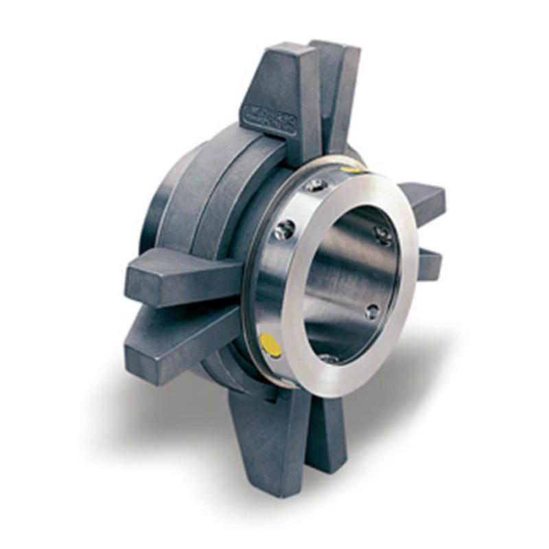
The stationary part of the seal is fitted to the pump housing with a static seal –this may be sealed with an o-ring or gasket clamped between the stationary part and the pump housing.
The rotary portion of the seal is sealed onto the shaft usually with an O ring. This sealing point can also be regarded as static as this part of the seal rotates with the shaft.
One part of the seal, either to static or rotary portion, is always resiliently mounted and spring loaded to accommodate any small shaft deflections, shaft movement due to bearing tolerances and out-of-perpendicular alignment due to manufacturing tolerances.
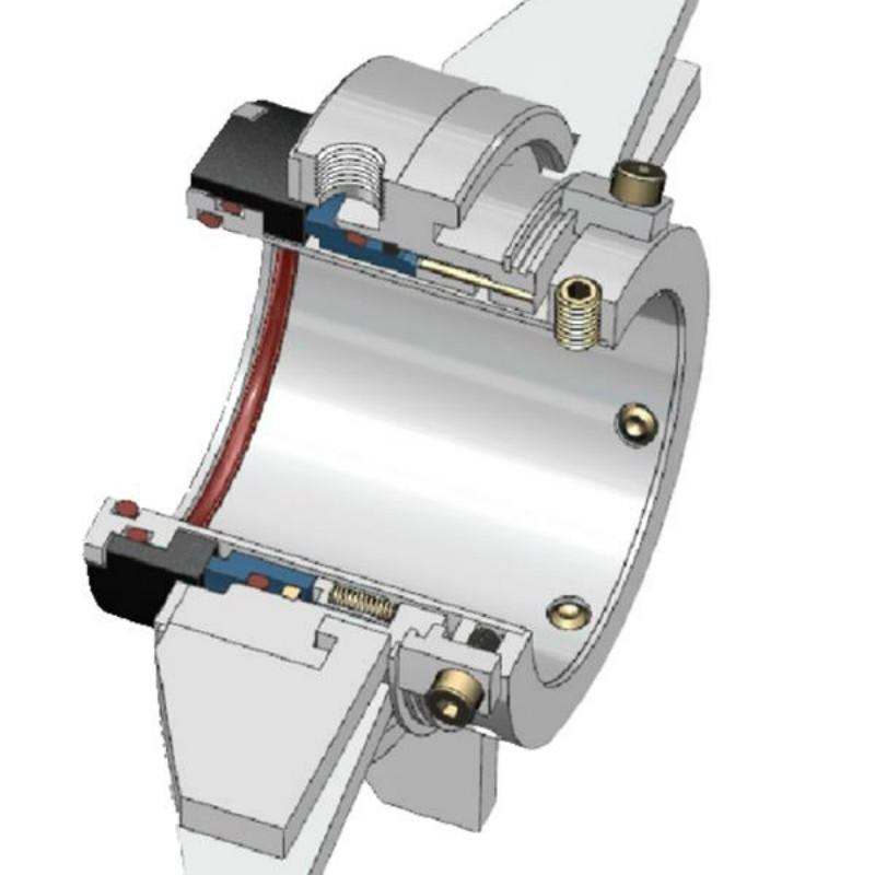
The primary seal is essentially a spring loaded vertical bearing - consisting of two extremely flat faces, one fixed, one rotating, running against each other. The seal faces are pushed together using a combination of hydraulic force from the sealed fluid and spring force from the seal design. In this way a seal is formed to prevent process leaking between the rotating (shaft) and stationary areas of the pump.
If the seal faces rotated against each other without some form of lubrication they would wear and quickly fail due to face friction and heat generation. For this reason some form of lubrication is required between the rotary and stationary seal face; this is known as the fluid film
In most mechanical seals the faces are kept lubricated by maintaining a thin film of fluid between the seal faces. This film can either come from the process fluid being pumped or from an external source.
The need for a fluid film between the faces presents a design challenge – allowing sufficient lubricant to flow between the seal faces without the seal leaking an unacceptable amount of process fluid, or allowing contaminants in between the faces that could damage the seal itself.
This is achieved by maintaining a precise gap between the faces that is large enough to allow in a small amounts of clean lubricating liquid but small enough to prevent contaminants from entering the gap between the seal faces.
The gap between the faces on a typical seal is as little as 1 micron – 75 times narrower than a human hair. Because the gap is so tiny, particles that would otherwise damage the seal faces are unable to enter, and the amount of liquid that leaks through this space is so small that it appears as vapor – around ½ a teaspoon a day on a typical application.
This micro-gap is maintained using springs and hydraulic force to push the seal faces together, while the pressure of the liquid between the faces (the fluid film) acts to push them apart.
Without the pressure pushing them apart the two seal faces would be in full contact, this is known as dry running and would lead to rapid seal failure.
Without the process pressure (and the force of the springs) pushing the faces together the seal faces would separate too far, and allow fluid to leak out.
Mechanical seal engineering focuses on increasing the longevity of the primary seal faces by ensuring a high quality of lubricating fluid, and by selecting appropriate seal face materials for the process being pumped.
When we talk about leakage we are referring to visible leakage of the seal. This is because as detailed above, a very thin fluid film holds the two seal faces apart from each other. By maintaining a micro-gap a leak path is created making it impossible for a mechanical seal to be totally leak free. What we can say, however, is that unlike gland packing, the amount of leakage on a mechanical seal should be so low as to be visually undetectable.
With a strict quality policy, alfa laval mechanical seal made by lepu seal factory is well known as a premier choice if user need the mechanical seal for their alfa lava LKH pumps, Especially for the multi-light screw on the seal ring, we have strong technology to make sure 100% right as original alfa laval seal design.
Guangzhou Lepu machinery CO., LTD becomes one of the leading mechanical seal supplier in south of china, we focus in designing and manufacturing mechanical seal for many kinds of famous brand pumps, our mechanical seal cover many kinds of industry like food, petrol chemical, paper making, sea ship, and so on.

A dry gas seal is a revolutionary way of sealing machines and protecting them from dust, moisture and other contaminants. A dry gas seal is a sealing device that uses pressurized gas to keep two surfaces from touching. The most common type of dry gas seal is the O-ring, which is used in many applications, including mechanical seals, piston rings, and gaskets. Dry gas seals are also used in many other industries, such as the food and beverage industry, where they are used to seal containers and prevent contamination. This type of seal not only helps to keep the machine running with maximum efficiency but also significantly reduce downtime, making it cost-effective in the long run. In this article, we"ll explore what a dry gas seal is, how it works and why you should consider using it for your machinery. By understanding the benefits of a dry gas seal and its uses, you can make an informed decision about the best sealing system for your needs. How does a dry gas seal work?Dry gas seals work by using a series of labyrinths to separate the high pressure seal gas from the atmosphere. The labyrinths are formed by a series of grooves and ridges on the surface of the seal ring. The seal ring is rotated at high speed, causing the gas to flow through the labyrinths. The gas is then forced through an aperture in the center of the seal ring, where it escapes into the atmosphere. What is a dry gas seal used for?Dry gas seals are used on rotating equipment to help minimize the leakage of high pressure gases from the inside of the machinery. This helps to reduce maintenance costs and improve safety. Dry gas seals are commonly used in applications such as pumps, compressors, turbines, and blowers. Advantages of a dry gas sealThere are many advantages of a dry gas mechanical seal. One advantage is that they are much simpler in design than other types of seals, making them more reliable and easier to maintain. Additionally, dry gas seals do not require the use of any lubricating fluids, which can leak or evaporate over time. This makes them more environmentally friendly and cost-effective in the long run. Finally, dry gas seals have a much longer lifespan than other types of seals, meaning that they need to be replaced less often.Disadvantages of a dry gas sealThere are several disadvantages of dry gas seals, including: - they can be expensive to purchase and install- they require careful maintenance and regular inspection- they can be susceptible to wear and tear- they can leak if not maintained properlyHow to choose the right dry gas seal for your applicationThere are a few key factors to consider when choosing the right dry gas mechanical seal for your application. The most important factor is the type of fluid being sealed. Gas seals are designed to seal either liquids or gases, but not both. Make sure to choose a gas seal that is compatible with the fluid you are sealing.Another important factor to consider is the pressure of the fluid being sealed. Gas seals are rated for different maximum pressures, so make sure to choose one that can handle the pressure of your application.Finally, take into account the size and shape of the sealing surfaces. Gas seals come in a variety of sizes and shapes to fit different applications, so make sure to choose one that will fit your needs.ConclusionDry gas seals are an extremely important component for many industrial operations, and their ability to prevent leaks has made them invaluable in a variety of applications. Understanding the basics of how dry gas mechanical seal work and how they can be used effectively is helpful when considering the various options available for any specific application. With the right choice, dry gas seals can provide reliable, leak-free performance which will save time, money and resources while ensuring safety and reliability. Lepu dry gas seal manufacturer provides best quality flowserve dry gas seal and dry gas seal. Welcome to contact us!
The global mechanical seals market size stood at USD 3.20 billion in 2018 and is projected to reach USD 4.77 billion by 2026, exhibiting a CAGR of 5.2% during the forecast period.
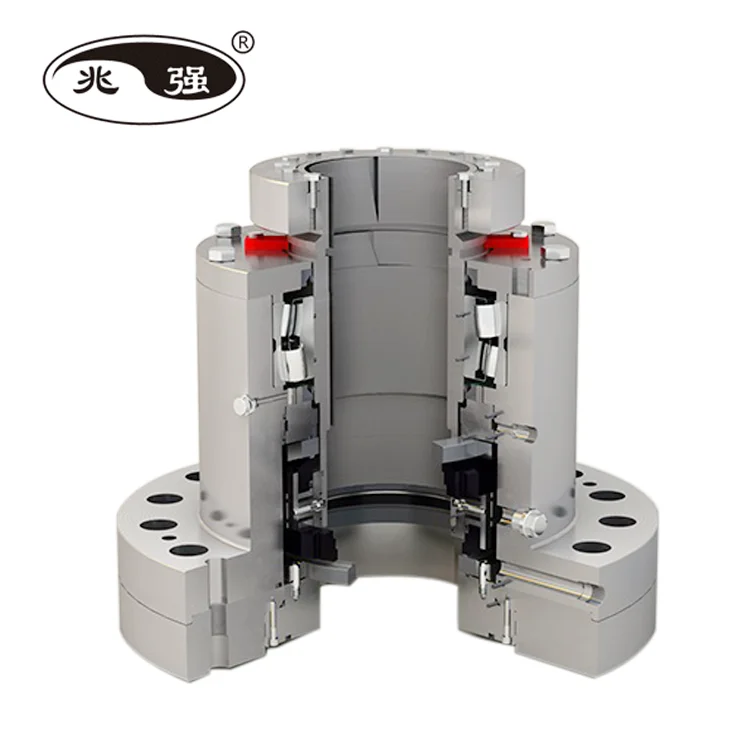
The key utility of a mechanical seal is to prevent leakage of fluids or gases through the clearance between the shaft and the container. Mechanical seals consist of a set of 2 faces separated by carbon rings. The first face is in contact with the rotating equipment whereas the second face is stationary. Moreover, the main part of the seal is the seal ring (first face) on which the mechanical force is acting, generated by springs, bellows, or fluids in the equipment. In recent years, mechanical seals are playing an important role in varied industrial applications, enabling efficient operations. Mechanical seals are made up of several flexible materials such as Polytetrafluoroethylene (PTFE), Polyurethane (AU, EU), industrial rubber, Fluorosilicone (FVMQ), and many more.
The mechanical seal market has depicted significant growth in the recent span of years and is likely to grow in the forecasted period. Rising industrial development in emerging economies is expected to initiate additional development policies and investments. Major types of mechanical seals available in the market include cartridge seals, balanced and unbalanced seals, pusher and non-pusher, and conventional seals that are influencing the mechanical sealing market growth in developing countries.
Growth in machine tool industry is impelling the overall market share, owing to the usage of power machines in centrifugal pumps and compressors for sealing and separating the fluid in the rotating shafts. Hence, the increasing market demand for mechanical seals in various industries is anticipated to drive the market growth in the near future. Furthermore, the highest market growth is projected to be witnessed in Asia-Pacific, followed by North America.
According to the United Nations Conference on Trade and Development (UNCTAD), the global foreign direct investment (FDI) will grow vigorously in 2018. This implies that there will be strong growth in the manufacturing sector in the coming decade. Moreover, many countries are now adopting investment policies that will boost the manufacturing sector and drive the mechanical seals market trends. For instance, in 2017, several countries and economies adopted investment policy measures across the globe, of which 84% of countries were favorable to investors. This will allow investors to invest their funds in various industries, with primary focus on energy, transportation, and manufacturing.
Therefore, the demand for manufacturing is increasing with the changes in investment policies of multiple developed and developing countries. This growth will increase the adoption of machine tools and industrial equipment for the manufacturing process, which will directly boost the mechanical seals market growth, globally.
The global mechanical seals market is segmented by type, which is further segmented into pusher and non-pusher, conventional seals, balanced and unbalanced seals, and cartridge seals.
Continuous adoption of advanced sealing material in several industries is expected to grow the cartridge seals segment in the forecast period. The cartridge seals segment is estimated to have exponential market opportunities as they are designed as universal shaft seals for the seal chamber of pumps, containers, or pipelines.
The pusher and non-pusher seals segment depicts substantial growth, owing to the increasing usage of small and large diameter ring shaft in the light end services to handle high temperatures. The balanced and unbalanced mechanical seals segment is anticipated to grow moderately, owing to the rise in the industry sector worldwide. Balanced seals are preferred for most of the industrial applications as they generate less heat at the surface of the machine, enabling longer seal life and efficient sealing method.
Comparatively, the conventional seal segment is projected to witness progressive growth owing to the requirement of heat exchanger mating ring advances offered by these seals. The other segment consists of bellows seals and is likely to represent steady growth due to limited demand in the mechanical sealing market.
Oil and gas industry is anticipated to grow exponentially at a higher growth rate owing to increasing demand of petroleum from developed and emerging countries, hence boosting the demand of mechanical seals. Energy utilization is growing worldwide and influencing the demand for electricity generation and consumption rate, thus leading to remarkable market growth. In the current scenario, 70% of the electricity is generated from the renewable sources such as wind and solar power, which bodes well for the mechanical seals market demand.
Mechanical seals demand is increasing in the food and beverage and mining sectors due to increasing implementation of pumps, food tanks, and many other centrifugal machines to manage the intensity of fluid. Marine sector is expected to depict substantial market growth as the need for the mechanical seals at naval ships and ports will remain steady in the forecast period. The others segment consists of chemical industry and is likely to showcase steady growth, owing to minimum demand in the mechanical sealing market.
Asia-Pacific is anticipated to lead the mechanical seals market share and is projected to depict exponential growth over the forecast period due to the increasing industrial applications in the emerging countries including India and China. Along with that, strong economic growth in the manufacturing sector is expected to fuel the development of the market in the region. Furthermore, favorable regulatory framework and regulations by governments for increasing investment in the manufacturing industry is expected to have a substantial impact in the growth of the market. Additionally, rapid industrialization and increasing demand of mechanical seals from industries such as construction, marine, energy and power, and oil and gas is expected to boost the growth of the market. Moreover, the region has several small and medium mechanical seals manufacturers which will increase the market share of the Asia-Pacific region in the forecasted period.
North America is predicted to show a dynamic growth rate over the projected timeline due to the rising number of infrastructure and other development projects in the region, the mechanical seals market analysis points out. This growth in the region is attributed to the presence of key players in the market along with increasing demand for mechanical seals in several industries such as manufacturing, oil & gas, and other mining industries. The growth is owed to deep involvement of workers with technology research and development (R&D) and STEM (science, technology, engineering, and mathematics) in the industries such as energy & power, oil & gas, and aerospace. Furthermore, the demand for the sealing products is accounted for increasing presence of manufacturing industries such as automotive and aerospace to energy industries such as oil and gas extraction to high-tech services such as computer software and computer system design, including health applications.
Furthermore, Europe is witnessing rapid growth owing to rising presence of chemical manufacturing industries along with growing use of sealing products in aerospace, rail, and marine industries. Additionally, demand for sealing products is comparatively stable as the large range of industries in the market offers a relatively balanced market growth over the years. The stability in demand can be seen in the period 2020-2024. Countries such as Italy and Spain are expected to show substantial growth compared to other countries in the region owing to the demand from major industries such as oil & gas and food & beverage.
The mechanical sealing market value in the Middle East and Africa is growing due to presence of more than 65% of global oil refineries in the region. Increasing investment in the oil industry will result in increased demand for mechanical seals. Moreover, countries of the Middle East are shifting their focus from oil and gas production to other industries such as tourism and other manufacturing industries which will result in decreasing market value of mechanical seals.
The manufacturing sector has declined in Latin America over the past few years owing to the decline in the production of cars and other equipment. Moreover, in 2015, the manufacturing production index of Latin America had declined by 0.9%, according to MAPI Foundation. The construction and oil and energy sub-segments are expected to grow at higher rate, owing to the increasing population and demand for the adoption of natural resources. Governments of Brazil, Mexico, and Argentina are working continuously on investing in green energy projects, which in turn will boost the adoption of mechanical seals in several different industries.
SKF (SKF AB), John Crane (Smiths Group Plc.), and Flowserve Corporation are the leading market players. SKF holds the largest market share, as per the mechanical seals market report. This is a result of SKF’s market understanding, along with demand forecasting, which is growing with customer-specific value propositions, giving the company an uptime for designing and production of mechanical seals. This fits with company’s existing engineering skills and asset management approach, with strategic focus on new technology providing value for money and digitalizing of the entire value chain.
Flowserve shares five unconsolidated joint ventures located in Latin America, Middle East, and Asia-Pacific regions, mainly in Saudi Arabia, India, The United Arab Emirates, South Korea, and two in China. The company has a portion of the products manufactured, assembled, or serviced in the territories. The joint venture has provided different strategic opportunities, including increased access to the potential markets, along with access to added manufacturing capacity and development of an efficient platform.
Furthermore, John Crane announced that it completed its purchase of the Engineering Division of Advanced Diamond Technologies. The acquisition of ADT will result in enhanced reliability and performance of mechanical seals in key settings in pumps along with other industrial equipment, bringing significant benefits to customers. Also, these strategies offer an enhanced product portfolio to their clients with minimum timelines.
The research report offers an in-depth analysis of the mechanical seals market. It further provides details on the adoption of mechanical seals products across several regions. Information on trends, drivers, opportunities, threats, and restraints of the market can further help stakeholders to gain valuable insights into the market. The report offers a detailed competitive landscape by presenting information on key players, along with their strategies, in the market.
March 2019:John Crane announced its new T4111 cartridge seal. The seal, called the Elastomer Bellows Cartridge Seal, is single-use and is designed to seal rotary and centrifugal pumps, along with similar rotating shaft machines.
April 2019:Dover announced the latest Air Mizer solutions design for the AM Conveyor Equipment Manufacturers Association shaft seal, which is explicitly developed for CEMA equipment & screw conveyors.
March 2018: Hallite Seals continued its third-party authentication with Milwaukee School of Engineering (MSOE) for the reliability & integrity of the design of its seals & sealing materials.
May 2017: Flowserve Corporation declared that it had completed the deal which involves sale of the Gestra AG unit to Spirax-Sarco Engineering plc. This sale was the part of Flowserve strategic decision to optimize its product range, enabling it to emphasis more on its core business activities and allowing it to be more competitive.

The invention relates to mechanical seals, and more particularly, to mechanical seals designed for gas applications in which the pressure differential across the seal is variable in direction.
End face mechanical seals, also referred to as mechanical face seals or simply as mechanical seals, are commonly used to isolate fluids in rotating equipment, such as pumps, mixers, blowers, and compressors. Typically, a pressure differential exists across the seal faces of a mechanical seal, which may vary in intensity during operation, but which typically remains constant in direction.
Mechanical seals generally require that a lubricant or other “cushioning substance” occupy the gap between the stationary and rotating seal face, so as to minimize frictional heating and premature wear. For many applications, the process fluid is a liquid that is used as the seal lubricant, whereby it is allowed to enter the seal and slowly leak past the seal faces. In other applications, for example when the process fluid is non-lubricating and/or toxic, a separate, pressurized lubrication system is provided that introduces a liquid lubricant into the seal, which then slowly leaks into the process, thereby preventing any escape of the process fluid into the surrounding environment.
In certain applications, the seal faces of a mechanical seal cannot be lubricated by a liquid. An example is a seal that separates a compressor from a bearing housing in a turbocharger of an internal combustion engine.
Turbochargers are used for both commercial and racing applications in a wide variety of vehicle engines, including gasoline and diesel engines. They pose some unique and challenging operating conditions for a seal. Temperatures in a turbocharger can rise up to 200° C., and shaft speeds can reach 120,000 rpm. In addition, the pressure within the compressor can range from vacuum up to more than 5 bar, which means that the pressure differential across the seal can change directions.
Accordingly, a seal for a turbocharger must be able to minimize the loss of compressed air from the compressor side of a seal into the bearing housing when the pressure in the compressor is high, for example during normal turbocharger operation and when the engine and turbocharger are rapidly accelerating. The seal must also be able to minimize leakage of oil from the bearing housing side of the seal into the compressor side during rapid engine deceleration, when vehicle braking occurs and a vacuum is created on the compressor side of the seal that tries to pull oil from the bearing housing side of the seal into the compressor.
Poor performance of the seal in a turbocharger therefore can cause both loss of compressed air and leakage of oil into the compressor, thereby reducing the performance of the turbocharger, and hence reducing the overall performance of the engine. Over the years, several approaches have been proposed for providing a seal between the bearing housing and compressor sections of a turbocharger. These have ranged from piston rings to labyrinth seals.
Mechanical seals designed for gas applications would be an attractive solution for turbochargers. While they tend to be somewhat complex, they offer distinct advantages in providing low air and/or oil leakage, as compared to the other types of seals that are normally used. One such mechanical seal design for a turbocharger is disclosed in U.S. Pat. No. 6,325,380 to Feigl, et al. Feigl discloses the use of a non-contacting mechanical gas seal that includes specific hydrodynamic features on at least one of the seal faces. In this design, illustrated in FIGS. 1 and 2, the air-filled compressor side is located at “A” and the bearing housing filled with oil is located at “B.” The seal faces are items 3 (stationary face) and 5 (rotating face).
FIG. 2 illustrates the use by Feigl of micro machined hydrodynamic face features 14 located at the inner diameter of the stationary face 3. These features 14 can also be located on the rotating face 5 as well. Feigl"s hydrodynamic seal face features 14 are micro machined grooves 14 in the seal face 3. Under rotating conditions, these grooves 14 pump and compress air into the gap between the faces 3, 5 and thereby generate lift between the faces 3, 5 for non-contact operation. The amount of lift (or face separation) can be controlled by careful design of the hydrodynamic features 14, based on the operating conditions of the turbocharger, especially its operational speed and the pressure. All else being equal, the separation between the faces 3, 5 will increase with increasing speed and pressure. Likewise, when the speed and pressure are decreased, the face separation will decrease as well.
One of the challenges with the Feigl approach, however, is that the hydrodynamic face features do not function when rapid car braking causes the turbocharger to reduce in speed, a vacuum is created within the compressor, and the pressure differential across the seal changes direction. Under these operating conditions, the face separation is dramatically reduced, because the hydrodynamic face features require air and compression to function appropriately. As a result, rapid deceleration can lead to unacceptable contact of the seal faces 3, 5 in the Feigl design, and can result in undue wear and seal face damage.
What is needed, therefore, is a mechanical seal designed for gas applications that can minimize leakage in both directions across the seal, so that undue leakage and wear of the seal faces is avoided even when the pressure differential across the seal changes direction, such as during rapid deceleration of a turbocharger.
A mechanical seal designed for gas applications is disclosed that minimizes leakage in both directions across the seal, so that undue leakage and wear of the seal faces is avoided even when the pressure differential across the seal changes direction, such as during rapid deceleration of a turbocharger.
The disclosed mechanical seal includes at least one sealing face in which are provided two sets of recessed face features, one set extending from the inner diameter of the face (the “ID” features) so as to admit gas into the gap between the seal faces from the inner diameter, and the other set extending from the outer diameter of the face (the “OD” features) so as to admit gas into the gap from the outer diameter.
In embodiments, the ID features function in a manner similar to the Feigl hydrodynamic features 14 shown in FIG. 2, in that they hydrodynamically maintain a cushion of compressed gas between the seal faces when the gas in the compressor is at a higher pressure than the gas in the bearing chamber. When the compressor side is under vacuum conditions, such that the ID features are functionally compromised, the OD features provide a cushion of compressed air between the seal faces by compressing air that is available from within the gearbox region, which is not under vacuum conditions. This ensures that the seal faces remain separated under all operating conditions, resulting in non-contact operation and significantly longer seal life of the seal. In embodiments, it is expected that the seal will last longer than the bearings.
In some embodiments, only one seal face includes the recessed features, while in other embodiments both of the seal faces include the recessed features. In still other embodiments, one of the seal faces includes the ID features, while the other seal face includes the OD features. In still other embodiments, the ID and OD features are distributed in other ways between the two seal faces.
In various embodiments where all of the ID and OD features are formed in the same seal face, the ratio of the seal face area that is covered by the ID and OD features, divided by the total seal face area, is at least 0.75 or greater. In some embodiments where the ID and OD features are distributed among the two seal faces, the ratio of the total area of both seal faces that is covered by the ID and OD features, divided by the total combined area of both seal faces, is at least 0.375 or greater.
Some embodiments of the present invention include a circumferential “seal dam” region on at least one of the seal faces into which the ID and OD features do not extend. In some of these embodiments, the seal dam region helps to further minimize leakage of air and other gases, as well as oil and other liquids, past the seal, especially under static conditions, for example if the bearing chamber of a turbocharger is overfilled or if the turbocharger is tipped at an unexpected angle during installation or other handling.
One general aspect of the present invention is a mechanical seal suitable for gas applications in which the pressure differential across the seal is variable in direction. The mechanical seal includes a substantially annular static seal face maintained in close, parallel relationship with a substantially annular rotatable seal face, the rotatable seal face being rotatable about a common axis of the seal faces, the seal faces being bounded by inner and outer face boundaries and separated from each other by a variable seal gap, a first plurality of recessed features formed in at least one of the seal faces, each of the first recessed features being configured to admit gas into the seal gap from only the inner boundary of the seal face in which it is formed, and a second plurality of recessed features formed in at least one of the seal faces, each of the second recessed features being configured to admit gas into the seal gap from only the outer boundary of the seal face in which it is formed.
In some embodiments, the first and second recessed features are formed in the static seal face, while in other embodiments the first and second recessed features are formed in the rotatable seal face, and in still other embodiments the first and second recessed features are distributed among both of the seal faces. In some of these embodiments all of the first recessed features are formed in one of the seal faces, and all of the second recessed features are formed in the other of the seal faces.
In any of the above embodiments, the second plurality of recessed features can be hydrodynamically shaped so as to pressurize gas admitted thereby into the seal gap. And in some of these embodiments the recessed features are able to pressurize gas within the seal gap to a pressure that is sufficient to cause face separation but is not sufficient to overcome centripetal effects, so that the recessed features are unable to cause seal leakage by driving fluids across the seal.
In any of the above embodiments wherein all of the first and second recessed features are formed in the same seal face, a ratio of a total area of the first and second recessed features divided by a total area of the seal face in which the recessed features are formed can be at least 0.75.
In any of the above embodiments wherein the first and second recessed features are distributed among the seal faces, a ratio of a total area of the first and second recessed features divided by a total area of both of the seal faces can be at least 0.375.
And in any of the above embodiments, at least one of the seal faces can include a circumferential seal dam region into which neither the first recessed features nor the second recessed features extend.
Another general aspect of the present invention is a turbocharger that includes a compressor actuated by a rotatable shaft, a lubricated bearing chamber configured to support the rotatable shaft, and a mechanical seal configured to isolate the lubricated bearing chamber from the compressor. The mechanical seal includes a substantially annular static seal face maintained in close, parallel relationship with a substantially annular rotatable seal face, the rotatable seal face being rotatably coupled to the rotatable shaft, the seal faces being coaxial about the rotatable shaft, bounded by inner and outer face boundaries, and separated from each other by a variable seal gap, a first plurality of recessed features formed in at least one of the seal faces, each of the first recessed features being configured to admit gas into the seal gap from only the inner boundary of the seal face in which it is formed, and a second plurality of recessed features formed in at least one of the seal faces, each of the second recessed features being configured to admit gas into the seal gap from only the outer boundary of the seal face in which it is formed.
In some embodiments, all of the first and second recessed features are formed in the static seal face. In other embodiments, all of the first and second recessed features are formed in the rotatable seal face. And in still other embodiments the first and second recessed features are distributed among both of the seal faces. In some of these embodiments, all of the first recessed features are formed in one of the seal faces, and all of the second recessed features are formed in the other of the seal faces.
In any of the above embodiments, at least one of the recessed features can be hydrodynamically shaped so as to pressurize gas admitted thereby into the seal gap. In some of these embodiments, the recessed features are able to pressurize gas within the seal gap to a pressure that is sufficient to cause face separation but is not sufficient to overcome centripetal effects, so that the recessed features are unable to cause seal leakage by driving fluids across the seal.
In any of the above embodiments in which all of the first and second recessed features are formed in the same seal face, a ratio of a total area of the first and second recessed features divided by a total area of the seal face in which the recessed features are formed can be at least 0.75.
In any of the above embodiments in which the first and second recessed features are distributed among the seal faces, a ratio of a total area of the first and second recessed features divided by a total area of both of the seal faces can be at least 0.375.
And in any of the above embodiments at least one of the seal faces can include a circumferential seal dam region into which neither the first recessed features nor the second recessed features extend.
FIG. 5 is a graph presenting as a function of rotation speed the pressure on the outer diameter of the mechanical seal that is required to overcome the centripetal affects forcing oil from the interface in an embodiment of the invention.
The present invention is a mechanical seal designed for gas applications that minimizes leakage in both directions across the seal, so that undue leakage and wear of the seal faces is avoided even when the pressure differential across the seal changes direction, such as during rapid deceleration of a turbocharger.
An embodiment 300 of the present invention applicable to a turbocharger is illustrated in FIGS. 3 and 4A. FIG. 3 is a side view of the seal 300 in this embodiment, in which regions A and B represent the compressor and oil sides of the seal, respectively. The static seal face is element 302, and the rotating seal face is element 304. In this embodiment, the actuation force is provided by a bellows 306, which enhances the high temperature tolerance of the seal 300. The recessed features 400, 402 in this embodiment are hydrodynamically shaped, and can be provided in either the rotating seal face 304 or static seal face 302. In the configuration shown in the Figures the recessed features are located on the rotating seal face 304.
FIG. 4A is a front view of a partial arc of the rotating seal face 304 of FIG. 3. The seal face includes one set 400 of hydrodynamic features extending outward from the inner diameter of the face (the “ID” features), and another set 402 of hydrodynamic features extending inward from the outer diameter of the face (the “OD” features). The ID features 400 function in a manner similar to the Feigl hydrodynamic features 14 shown in FIG. 2, by maintaining a cushion of compressed gas between the seal faces thereby producing non-contacting conditions during normal operation when the gas in the compressor is at a higher pressure than the air in the bearing chamber.
When the compressor side A is under vacuum conditions and the ID features 400 are not able to provide a sufficient gas cushion, the OD features 402 provide lift between the seal faces 302, 304 by compressing air that is available from within the gearbox region B, which is not under vacuum conditions. This ensures that the seal faces 302, 304 remain separated under all operating conditions, resulting in non-contact operation and significantly longer life of the seal 300. It is expected that the seal 300 will last longer than the bearings (not shown).
As shown in FIG. 4B, in embodiments of the present invention, such as the embodiment of FIG. 4A, the OD 402 and ID 400 features are arranged such that there is a circumferential “seal dam” region 404 provided between them on at least one seal face between the OD features 402 and the ID features 400. This seal dam region 404 is simply a circumferential region of the seal face into which neither the ID features 400 nor the OD features 402 extend. In embodiments, arranging the ID 400 and OD 402 features such that there is a seal dam region 404 between them helps to further minimize leakage of air and other gases, as well as oil and other liquids, past the seal, especially under static conditions, for example if the bearing chamber of a turbocharger is overfilled or if the turbocharger is tipped at an unexpected angle during installation or other handling.
It should be noted that, while all of the recessed features 400, 402 in the embodiment of FIGS. 3 and 4A are formed in the same seal face 304, the scope of the present invention extends to any distribution of the recessed features 400, 402, including distributions in which all of the ID features 400 are formed in one face and all of the OD features 402 are formed in the other face, as well as to embodiments in which the ID and OD features are distributed in any manner among the two seal faces.
It should also be noted that while the features 400, 402 in the embodiment of FIGS. 3 and 4A are described as being “hydrodynamic,” because they are curved so as to provide a “pumping” action that actively pumps gas into the gap between the seal faces and pressurizes it, nevertheless the scope of the present invention extends to features of any shape, so long as each of the features is configured to admit gas into the gap from either the outer or the inner diameter of the seal faces, but not both.
Because the OD features 402 in the embodiment of FIGS. 3 and 4A are essentially hydrodynamic pumping features, it is important to ensure that oil on the bearing side B of the seal 300 is not pumped across the seal faces 302, 304 and into the compressor side A when the turbocharger is under vacuum conditions during deceleration. The hydrodynamic nature of the OD features 402 in this embodiment causes the developed pressure of the gas cushion within the gap between the seal faces 302, 304 to increase as the rotational speed of the rotatable seal face 304 increases. Accordingly, in embodiments the OD features 402 are configured such that they can generate a pressure sufficient to cause face separation, but cannot generate sufficient pressure to cause oil to migrate from the bearing side B of the seal to the compressor side A. This ensures that the centripetal effects which tend to eject oil from the seal 300 are stronger than the pressure differential and pumping effect of the OD features.
Since the rotating seal face 304 acts as an oil “slinger,” ejecting oil away from the seal faces 302, 304, the amount of differential pressure required to “push” the oil through the gap from the outer diameter to the inner diameter of the seal faces can be calculated as a function of rotation rate. The result of such a calculation for an embodiment of the present invention is shown in FIG. 5. It can be seen from the figure that the OD pumping features 402 would have to develop significant pressures to overcome centripetal effects and allow oil to escape into the compressor side A.
In various embodiments such as the embodiment of FIGS. 3 and 4, where all of the ID and OD features are formed in the same seal face, the ratio of the seal face area that is covered by the ID and OD features, divided by the total seal face area, is at least 0.75 or greater. In some other embodiments where the ID and OD features are distributed among the two seal faces, the ratio of the total area of both seal faces that is covered by the ID and OD features, divided by the total combined area of both seal faces, is at least 0.375 or greater.

The Reactor Mechanical Seals industry’s market size, characteristics, and growth are detailed in this report, which is broken down by type, application, and consumption area of Reactor Mechanical Seals. The report also describes the leading companies and introduces players in the industry from the standpoint of the industry chain and marketing chain.
JohnCrane, EagleBurgmann, Flowserve, AESSEAL, MeccanotecnicaUmbra, VULCAN, Garlock, Sunnyseal, OerlikonBalzers, KSB, Colossus, Sulzer, Flex-A-Seal, Chesterton, Valmet, Ekato, Xi’anYonghua, Fluiten, JamesWalker, HuayangSeals, HuhnsealAB
The study examines and assesses the global Reactor Mechanical Seals Market ‘s potential, including facts and data on market size, share, and growth variables. In addition, the research identifies and analyses developing trends in the global blood ingredients market, as well as main drivers, challenges, and opportunities. The market has had significant growth at a notable rate in recent years and is expected to continue to rise as a result of its increasing use in products. Furthermore, increased industry knowledge in China, the launch of new and specialised products, rising population, and significant increases in spending are expected to support market growth in the future. However, the high cost of treatment and rising demand for such products are projected to limit market expansion.
The global Reactor Mechanical Seals Market 2022 research analyses market size, share, and growth, as well as trends, pricing structure, and statistics and detailed data. The examination of several aspects that contribute to the market’s growth has been included in the research report. This section also discusses the many sectors and applications that may have an impact on the market in the future. This section also includes a breakdown of production volume on the global market and by kind from 2022 to 2028. The market is categorised in this research report based on the source of their production technique, type, and application.


 8613371530291