
bellow mechanical seal free sample
1. bellow type mechanical seal design ensures high reliability and a long service life of bellow seal . With highly advanced technology, Lepu seals can ensure better productivity for you
2. The product is highly fuel-efficient. Thus, it helps in reducing CO2 considerably and help companies put their greener footprint forward. Lepu seals can ensure high efficiency
3. The product has a smooth and flat surface. The singeing technique which quickly passes yarn or fabric through a flame or rubs it over a hot metal surface to remove the surface hairs. The seal face uses high quality SSIC for stationary and rotary
4. The product features sound absorption. It is capable of blocking airborne sound and its construction is ensured that there are no gaps and leaks. Lepu seal is made of strong quality stainless steel
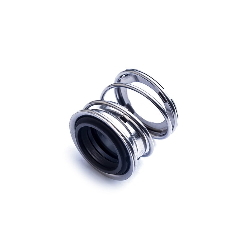
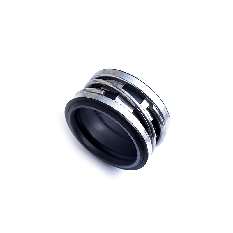
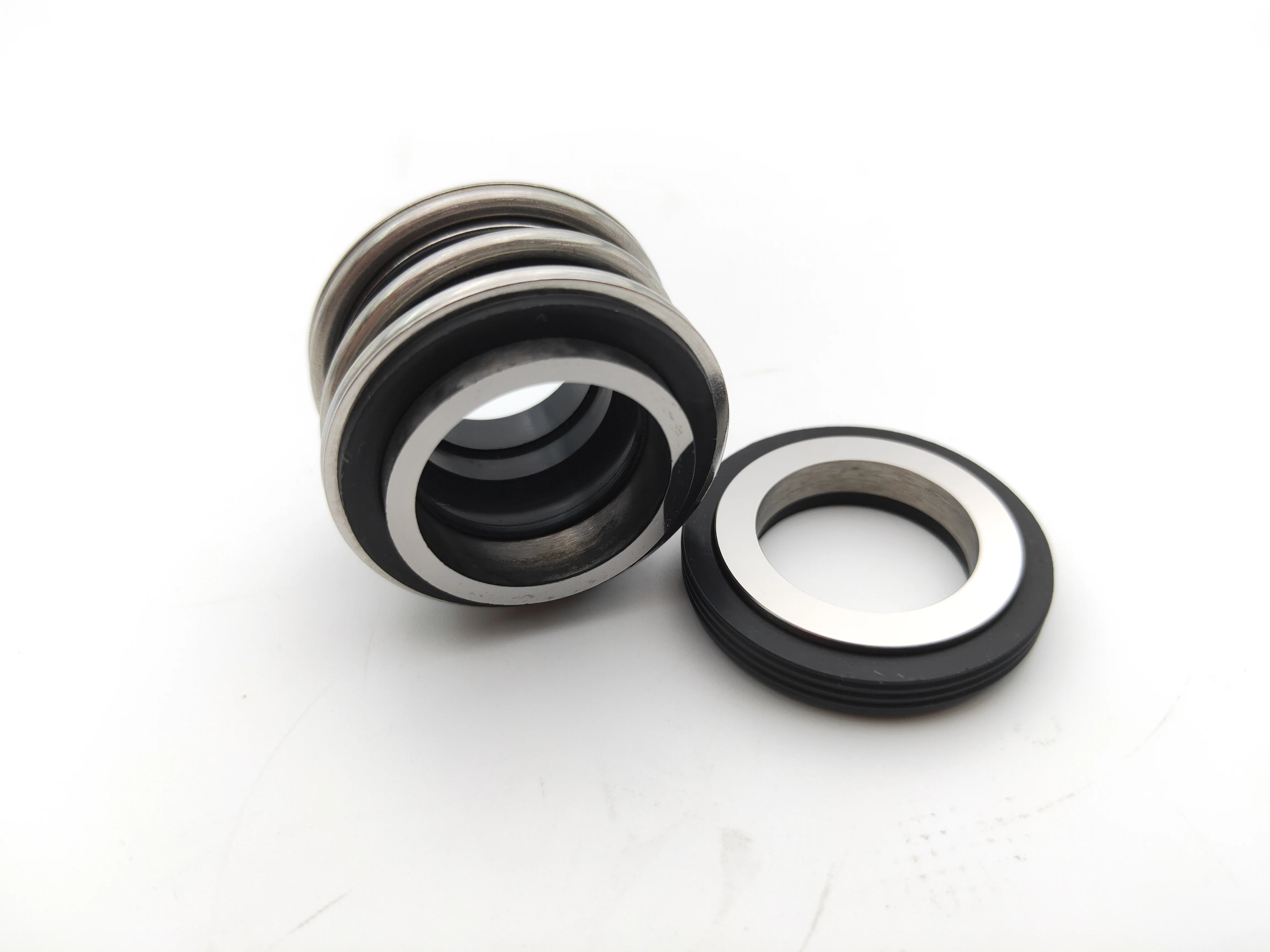
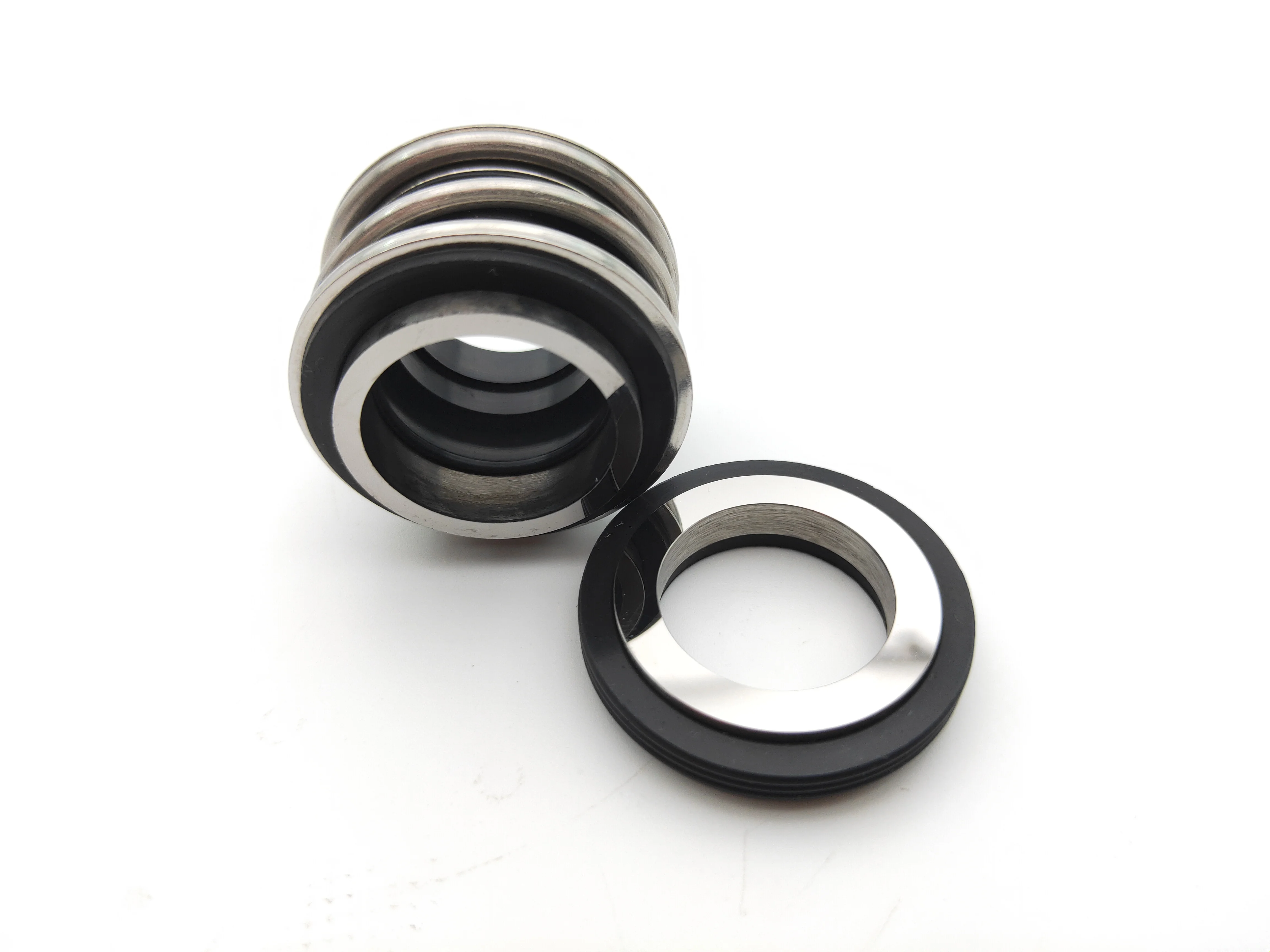
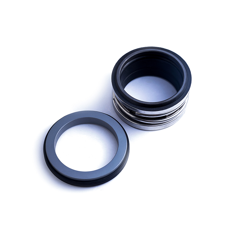
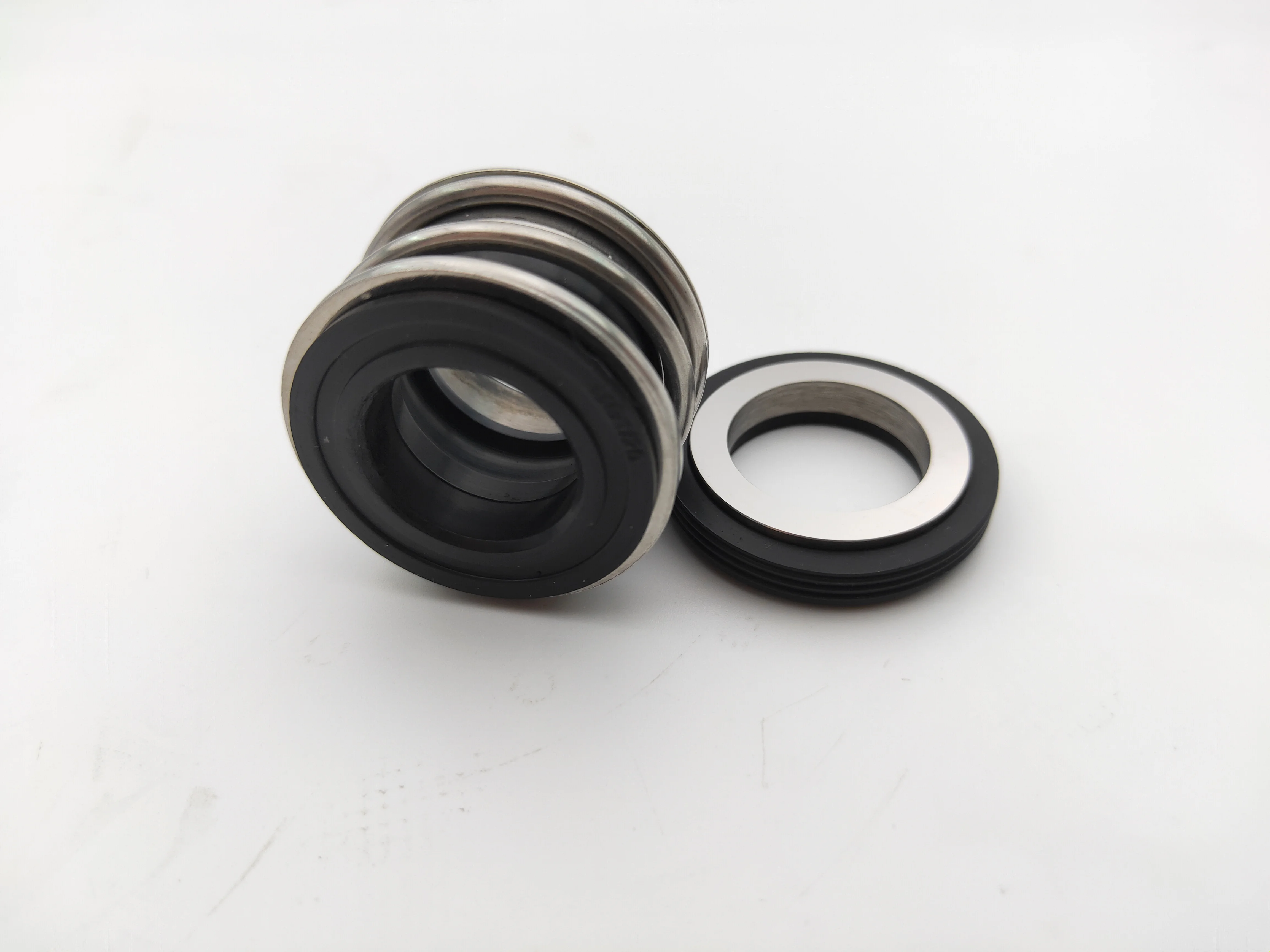
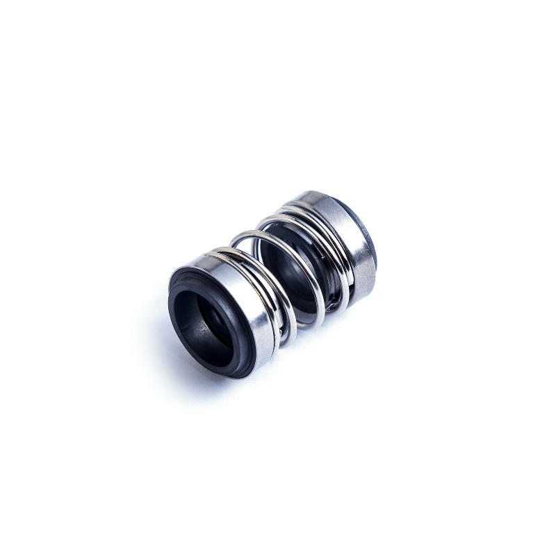
Compact, unitized, single-spring elastomer bellows seal, that is what we calling John crane mechanical seal 2100/2102/2103, offers maximum durability and performance in many demanding applications.
There are 3 kinds of tail for john crane mechanical seal type 2100, the normal size tail is we call 2100, and middle longer tail is 2102, the longest tail mechanical seal is 2103, please choose the right size base when buying this 2100 john crane seal.
Guangzhou Lepu machinery CO., LTD becomes one of the leading mechanical seal supplier in south of china, we focus in designing and manufacturing mechanical seal for many kinds of famous brand pumps, our mechanical seal cover many kinds of industry like food, petrol chemical, paper making, sea ship, and so on.
1. With years of development, Guangzhou Lepu Machinery CO., LTD has made remarkable achievements in the R&D, design, and production of bellow type mechanical seal .
A dry gas seal is a revolutionary way of sealing machines and protecting them from dust, moisture and other contaminants. A dry gas seal is a sealing device that uses pressurized gas to keep two surfaces from touching. The most common type of dry gas seal is the O-ring, which is used in many applications, including mechanical seals, piston rings, and gaskets. Dry gas seals are also used in many other industries, such as the food and beverage industry, where they are used to seal containers and prevent contamination. This type of seal not only helps to keep the machine running with maximum efficiency but also significantly reduce downtime, making it cost-effective in the long run. In this article, we"ll explore what a dry gas seal is, how it works and why you should consider using it for your machinery. By understanding the benefits of a dry gas seal and its uses, you can make an informed decision about the best sealing system for your needs. How does a dry gas seal work?Dry gas seals work by using a series of labyrinths to separate the high pressure seal gas from the atmosphere. The labyrinths are formed by a series of grooves and ridges on the surface of the seal ring. The seal ring is rotated at high speed, causing the gas to flow through the labyrinths. The gas is then forced through an aperture in the center of the seal ring, where it escapes into the atmosphere. What is a dry gas seal used for?Dry gas seals are used on rotating equipment to help minimize the leakage of high pressure gases from the inside of the machinery. This helps to reduce maintenance costs and improve safety. Dry gas seals are commonly used in applications such as pumps, compressors, turbines, and blowers. Advantages of a dry gas sealThere are many advantages of a dry gas mechanical seal. One advantage is that they are much simpler in design than other types of seals, making them more reliable and easier to maintain. Additionally, dry gas seals do not require the use of any lubricating fluids, which can leak or evaporate over time. This makes them more environmentally friendly and cost-effective in the long run. Finally, dry gas seals have a much longer lifespan than other types of seals, meaning that they need to be replaced less often.Disadvantages of a dry gas sealThere are several disadvantages of dry gas seals, including: - they can be expensive to purchase and install- they require careful maintenance and regular inspection- they can be susceptible to wear and tear- they can leak if not maintained properlyHow to choose the right dry gas seal for your applicationThere are a few key factors to consider when choosing the right dry gas mechanical seal for your application. The most important factor is the type of fluid being sealed. Gas seals are designed to seal either liquids or gases, but not both. Make sure to choose a gas seal that is compatible with the fluid you are sealing.Another important factor to consider is the pressure of the fluid being sealed. Gas seals are rated for different maximum pressures, so make sure to choose one that can handle the pressure of your application.Finally, take into account the size and shape of the sealing surfaces. Gas seals come in a variety of sizes and shapes to fit different applications, so make sure to choose one that will fit your needs.ConclusionDry gas seals are an extremely important component for many industrial operations, and their ability to prevent leaks has made them invaluable in a variety of applications. Understanding the basics of how dry gas mechanical seal work and how they can be used effectively is helpful when considering the various options available for any specific application. With the right choice, dry gas seals can provide reliable, leak-free performance which will save time, money and resources while ensuring safety and reliability. Lepu dry gas seal manufacturer provides best quality flowserve dry gas seal and dry gas seal. Welcome to contact us!
A Bellows seal does not have a secondary seal that must move along the shaft or sleeve to maintain seal face contact. The secondary seal is static state at all times, even when the pump is in operation.
Primary seal face wear is typically accommodated by welded metal or elastomeric bellows which move to assist in the compression of the rotary to stationary seal faces.
Bellows seals allow for high and low temperature applications when used in conjunction with metal bellows. They do not require a rotating secondary seal, which means it is not prone to secondary seal hang-up or fretting along the shaft or sleeve.

The global mechanical seals market size stood at USD 3.20 billion in 2018 and is projected to reach USD 4.77 billion by 2026, exhibiting a CAGR of 5.2% during the forecast period.
The key utility of a mechanical seal is to prevent leakage of fluids or gases through the clearance between the shaft and the container. Mechanical seals consist of a set of 2 faces separated by carbon rings. The first face is in contact with the rotating equipment whereas the second face is stationary. Moreover, the main part of the seal is the seal ring (first face) on which the mechanical force is acting, generated by springs, bellows, or fluids in the equipment. In recent years, mechanical seals are playing an important role in varied industrial applications, enabling efficient operations. Mechanical seals are made up of several flexible materials such as Polytetrafluoroethylene (PTFE), Polyurethane (AU, EU), industrial rubber, Fluorosilicone (FVMQ), and many more.
The mechanical seal market has depicted significant growth in the recent span of years and is likely to grow in the forecasted period. Rising industrial development in emerging economies is expected to initiate additional development policies and investments. Major types of mechanical seals available in the market include cartridge seals, balanced and unbalanced seals, pusher and non-pusher, and conventional seals that are influencing the mechanical sealing market growth in developing countries.
Growth in machine tool industry is impelling the overall market share, owing to the usage of power machines in centrifugal pumps and compressors for sealing and separating the fluid in the rotating shafts. Hence, the increasing market demand for mechanical seals in various industries is anticipated to drive the market growth in the near future. Furthermore, the highest market growth is projected to be witnessed in Asia-Pacific, followed by North America.
According to the United Nations Conference on Trade and Development (UNCTAD), the global foreign direct investment (FDI) will grow vigorously in 2018. This implies that there will be strong growth in the manufacturing sector in the coming decade. Moreover, many countries are now adopting investment policies that will boost the manufacturing sector and drive the mechanical seals market trends. For instance, in 2017, several countries and economies adopted investment policy measures across the globe, of which 84% of countries were favorable to investors. This will allow investors to invest their funds in various industries, with primary focus on energy, transportation, and manufacturing.
Therefore, the demand for manufacturing is increasing with the changes in investment policies of multiple developed and developing countries. This growth will increase the adoption of machine tools and industrial equipment for the manufacturing process, which will directly boost the mechanical seals market growth, globally.
The global mechanical seals market is segmented by type, which is further segmented into pusher and non-pusher, conventional seals, balanced and unbalanced seals, and cartridge seals.
Continuous adoption of advanced sealing material in several industries is expected to grow the cartridge seals segment in the forecast period. The cartridge seals segment is estimated to have exponential market opportunities as they are designed as universal shaft seals for the seal chamber of pumps, containers, or pipelines.
The pusher and non-pusher seals segment depicts substantial growth, owing to the increasing usage of small and large diameter ring shaft in the light end services to handle high temperatures. The balanced and unbalanced mechanical seals segment is anticipated to grow moderately, owing to the rise in the industry sector worldwide. Balanced seals are preferred for most of the industrial applications as they generate less heat at the surface of the machine, enabling longer seal life and efficient sealing method.
Comparatively, the conventional seal segment is projected to witness progressive growth owing to the requirement of heat exchanger mating ring advances offered by these seals. The other segment consists of bellows seals and is likely to represent steady growth due to limited demand in the mechanical sealing market.
Oil and gas industry is anticipated to grow exponentially at a higher growth rate owing to increasing demand of petroleum from developed and emerging countries, hence boosting the demand of mechanical seals. Energy utilization is growing worldwide and influencing the demand for electricity generation and consumption rate, thus leading to remarkable market growth. In the current scenario, 70% of the electricity is generated from the renewable sources such as wind and solar power, which bodes well for the mechanical seals market demand.
Mechanical seals demand is increasing in the food and beverage and mining sectors due to increasing implementation of pumps, food tanks, and many other centrifugal machines to manage the intensity of fluid. Marine sector is expected to depict substantial market growth as the need for the mechanical seals at naval ships and ports will remain steady in the forecast period. The others segment consists of chemical industry and is likely to showcase steady growth, owing to minimum demand in the mechanical sealing market.
Asia-Pacific is anticipated to lead the mechanical seals market share and is projected to depict exponential growth over the forecast period due to the increasing industrial applications in the emerging countries including India and China. Along with that, strong economic growth in the manufacturing sector is expected to fuel the development of the market in the region. Furthermore, favorable regulatory framework and regulations by governments for increasing investment in the manufacturing industry is expected to have a substantial impact in the growth of the market. Additionally, rapid industrialization and increasing demand of mechanical seals from industries such as construction, marine, energy and power, and oil and gas is expected to boost the growth of the market. Moreover, the region has several small and medium mechanical seals manufacturers which will increase the market share of the Asia-Pacific region in the forecasted period.
North America is predicted to show a dynamic growth rate over the projected timeline due to the rising number of infrastructure and other development projects in the region, the mechanical seals market analysis points out. This growth in the region is attributed to the presence of key players in the market along with increasing demand for mechanical seals in several industries such as manufacturing, oil & gas, and other mining industries. The growth is owed to deep involvement of workers with technology research and development (R&D) and STEM (science, technology, engineering, and mathematics) in the industries such as energy & power, oil & gas, and aerospace. Furthermore, the demand for the sealing products is accounted for increasing presence of manufacturing industries such as automotive and aerospace to energy industries such as oil and gas extraction to high-tech services such as computer software and computer system design, including health applications.
Furthermore, Europe is witnessing rapid growth owing to rising presence of chemical manufacturing industries along with growing use of sealing products in aerospace, rail, and marine industries. Additionally, demand for sealing products is comparatively stable as the large range of industries in the market offers a relatively balanced market growth over the years. The stability in demand can be seen in the period 2020-2024. Countries such as Italy and Spain are expected to show substantial growth compared to other countries in the region owing to the demand from major industries such as oil & gas and food & beverage.
The mechanical sealing market value in the Middle East and Africa is growing due to presence of more than 65% of global oil refineries in the region. Increasing investment in the oil industry will result in increased demand for mechanical seals. Moreover, countries of the Middle East are shifting their focus from oil and gas production to other industries such as tourism and other manufacturing industries which will result in decreasing market value of mechanical seals.
The manufacturing sector has declined in Latin America over the past few years owing to the decline in the production of cars and other equipment. Moreover, in 2015, the manufacturing production index of Latin America had declined by 0.9%, according to MAPI Foundation. The construction and oil and energy sub-segments are expected to grow at higher rate, owing to the increasing population and demand for the adoption of natural resources. Governments of Brazil, Mexico, and Argentina are working continuously on investing in green energy projects, which in turn will boost the adoption of mechanical seals in several different industries.
SKF (SKF AB), John Crane (Smiths Group Plc.), and Flowserve Corporation are the leading market players. SKF holds the largest market share, as per the mechanical seals market report. This is a result of SKF’s market understanding, along with demand forecasting, which is growing with customer-specific value propositions, giving the company an uptime for designing and production of mechanical seals. This fits with company’s existing engineering skills and asset management approach, with strategic focus on new technology providing value for money and digitalizing of the entire value chain.
Furthermore, John Crane announced that it completed its purchase of the Engineering Division of Advanced Diamond Technologies. The acquisition of ADT will result in enhanced reliability and performance of mechanical seals in key settings in pumps along with other industrial equipment, bringing significant benefits to customers. Also, these strategies offer an enhanced product portfolio to their clients with minimum timelines.
The research report offers an in-depth analysis of the mechanical seals market. It further provides details on the adoption of mechanical seals products across several regions. Information on trends, drivers, opportunities, threats, and restraints of the market can further help stakeholders to gain valuable insights into the market. The report offers a detailed competitive landscape by presenting information on key players, along with their strategies, in the market.
March 2019:John Crane announced its new T4111 cartridge seal. The seal, called the Elastomer Bellows Cartridge Seal, is single-use and is designed to seal rotary and centrifugal pumps, along with similar rotating shaft machines.
April 2019:Dover announced the latest Air Mizer solutions design for the AM Conveyor Equipment Manufacturers Association shaft seal, which is explicitly developed for CEMA equipment & screw conveyors.
March 2018: Hallite Seals continued its third-party authentication with Milwaukee School of Engineering (MSOE) for the reliability & integrity of the design of its seals & sealing materials.
Since failure of the mechanical seal on the shaft is the number one cause of pump shutting down, it is important to know the standard terms of the world of mechanical seals.
Mechanical seals are comparable to precision instruments. These seals use margins with many decimal places. The mechanical seal life depends on many factors, and it can vary from a few intense minutes to many trouble-free years. In general it can be stated that: the more attention paid to the mechanical seal and related equipment, the longer they will last.
Years ago, packing materials such as stuffing box packing were used for most shaft seals. These types of shaft seals required a fair amount of leakage to keep the packing properly lubricated and cooled. Until 1915 the mechanical seal was invented. This shaft seal managed to keep the fluid in by using two incredibly flat surfaces (one that rotates with the shaft, and one stationary in the housing). Despite the fact that these treads also need a little bit of ‘leakage’ to create a hydrodynamic layer, this is often not noticeable as this liquid evaporates. Most pumps today have mechanical seals. However, because the parts and surfaces are so delicate, it is also the number one cause of pump failure. This requires a better understanding of this type of seal and its application.
A set of (very flat lapped) treads as primary seal: the minimum distance between these treads, which are perpendicular to the shaft, minimizes the leakage. Often two different materials are used as the tread, a harder and a softer material, to prevent the materials from sticking together. One of the treads is often anti-friction corrosion material such as carbon graphite. A relatively hard material such as silicon carbide (SiC) or ceramic alumina is often used for the other tread. However, when processing abrasive substances, two hard surfaces are normally used.A tread is mounted stationary in a house.
Mechanical seals require a fluid to maintain lubrication. The running surfaces are usually lubricated by a very thin layer of liquid (or gas) between the two running surfaces. Lubrication can also come from another fluid other than the product, depending on the seal requirements.
Pusher seals use a secondary seal that moves axially along the shaft or shaft sleeve to maintain pressure on the running surfaces. This allows the seal to compensate for wear and any less accurate shaft alignment. The advantage is that this seal type is the cheapest. The main disadvantage of this configuration is that the secondary seal can gall on the shaft or shaft sleeve, especially when processing abrasive product.
This is the category in which the bellow seals fall. These seals do not use a secondary seal that must be able to move along the shaft or shaft sleeve to maintain contact. The secondary seals do not move with this type of seal under any circumstances, not even during use. The tread wear is compensated for by an elastomer or metal bellows. A disadvantage of this type of seal is the higher cost price of the seal and that a larger seal must be used in a corrosive environment because the material of the bellows is otherwise too thin.
We speak of a balanced seal if the pressure on the running surfaces caused by the pressure in the system is taken into account. It may sound crazy if the goal is to achieve shaft seal, but a mechanical seal must leak! After all, the running surfaces of the primary seal must be lubricated with the pumped product. When the pressure on the product side exceeds approximately 250 psid, the pressure on the treads can increase to such an extent that no liquid film can form between the surfaces. The lack of lubricating film will cause the seals to wear out very quickly.
To overcome this problem, the balanced seal was introduced in 1938. With a balanced mechanical seal, high pressure is taken into account by adjusting the surface of the tread, which distributes the stuffing box pressure over a larger surface. Balanced seals are easy to recognize, there is a step in the shaft sleeve and/or the running surface. Incidentally, this works a bit more complicated with a metal bellow, but the principle remains the same. Mechanical seals can also be designed to balance for overpressure on both sides of the tread assembly.
Cartridge seals consist of a pre-mounted mechanical seal on a shaft sleeve that can be installed as a whole over the shaft or shaft sleeve. Cartridge seals are very easy to install and the chance of short service life due to suboptimal installation is less probable. It should come as no surprise that cartridge seals are a lot more expensive than the previously discussed seals. On the other hand, there are lower maintenance costs. Incidentally, it is not always possible to apply a cartridge seal if, for example, there is no space in the house.
Yes, Flexaseal’s edge-welded bellows are completely manufactured at our Vermont factory. Our welding department and engineering staff work closely together to control the manufacturing quality of all bellows assemblies, from stamping sheets of foil stock through welding cores and end fittings, evaluating spring rates, and pressure testing the completed assembly. We use the TIG (Tungsten Inert Gas) welding process which provides the finest control of the weld arc, resulting in efficient, clean, and long-lasting welds.
Formed bellows are manufactured from either welded (seamed) or seamless tubing and utilize extensive automation for mass production. This process offers some cost benefits over edge-welded bellows assemblies however, formed bellows are limited to materials which can be elongated through either rolling or hydroforming. Formed bellows typically have thicker convolution structure with higher spring rates and larger deviations than edge-welded bellows which impacts precision loading.
Flexaseal designs and manufactures edge-welded bellows. Our bellows production begins by stamping male and female diaphragms from sheet (foil) stock. We inventory foil stock including various Hastelloy™ and Inconel® grades, titanium and Monel® as well as cryogenic-grade materials, to accommodate a wide range of applications. Diaphragms are TIG-welded together to create a convolution, and these convolutions are assembled together and welded to create the bellows core. Bellows core sizes can range from just a few welded convolutions to 100+ convolutions for a hermetic bellows assembly.
Contrary to popular belief, it is possible to repair a rotary bellows assembly. If pressure testing reveals leakage around the seal face, Flexaseal will de-insert the current face and check the retainer for any damage. If the retainer is within the necessary tolerances, FAS will insert a new face into the assembly as well as replace the other wear parts (O-ring and hardware).
If the bellows rotary shows visible damage to either the bellows core or end fittings, or a pressure test reveals leaks in the assembly itself, Flexaseal recommends a new bellows assembly to ensure sealing integrity.
In a pusher seal design, the secondary sealing component – usually an O-ring or a wedge — must move axially to compensate for wear, vibrations, and movements of the shaft.
Welded bellows assemblies also offer the benefit of an inherently balanced seal design. Mechanical seal balance refers to the ratio of the opening and closing areas of the seal faces. Both a balanced and unbalanced design may have the same opening face area but the balanced seal’s closing area is smaller, reducing the load on the faces. This reduced load means less heat generated at the seal faces, enabling the balanced seal to run cooler than an unbalanced seal design. This cooler operating environment positively impacts a seal’s run time.
If your facility must comply with API Standard 682 which requires all Type B or C cartridge seals to utilize a balanced seal design, standardizing on hydraulically balanced, welded metal bellows seals ensures satisfactory seal run time and low seal maintenance for your equipment.
Operating length (OL) - also referred to as installed or working length: The axial length of a bellows assembly as installed to the designed compression. The term may also refer to the dimensional range within which a bellows assembly can safely be operated.
Mechanical seals, whether a pusher or bellows design, need a specific amount of compression to ensure the faces are in contact to maintain the correct amount of lubrication to operate (dry-running seal designs are the exception to this statement.) Both the Free Length and Operating Length are necessary for this compression calculation: Free Length – Operating Length = amount of compression. Here’s an example:
Specially designed for cryogenic temperatures and high temperatures, mechanical seals with metal bellows are used when mechanical seals with elastomeric components are not adaptable to extreme temperatures. Our proprietary metal bellows allow us to design and recommend the most efficient solutions to meet your specific application parameters and operation requirements.
An end face mechanical seal is a device intended to prevent or minimize leakage from a vessel through the clearance around a rotating shaft entering that vessel. Perhaps the most common example is the end face mechanical seal used in the water pump of an automobile engine. Most pumps used in petroleum refineries, chemical plant and pipelines also use end face mechanical seals.
The simplest possible mechanical end face seal consists of a shoulder on a rotating shaft which rubs against a stationary case. This concept is shown in Figure 3.
As with packing or any bearing material, lubrication and cooling are required to prevent heat buildup and wear. Hydraulic pressure tends to force fluid between the faces and provide a lubricating film but the face separation must be kept very small to minimize leakage. Cooling is provided by the surrounding liquid. The conceptual design shown in Figure 3 is very simple, but it demonstrates the basic principle of the end face mechanical seals. Of course, it has functional drawbacks which must be addressed.
Seal face leakage is governed by many variables, but the dominant variable is face separation. A variation of a few micro-inches (millionths of an inch) in the face separation can cause significant changes in leakage. Unfortunately, shaft movement can amount to several thousandths of an inch.
A practical approach to overcoming shaft movement is to mount one of the seal faces in a flexible manner so that it can move axially. Obviously a desirable feature, this flexibility is a prerequisite for effective seal design.
Figure 4 shows an improved seal as compared to Figure 3. In Figure 4, The sealing shoulder on the shaft has been removed and replaced with a component which is not permanently attached to the shaft. This component is called the primary ring. The “face” of the primary ring rubs against the mating ring. Since the primary ring and the shaft are two separate parts, an additional sealing device must be used to prevent leakage between the shaft and primary ring. The flexibly mounted primary ring can compensate for the small variations in movement on the axial plane. It can also adjust for seal face wear. Figure 4 is a very simple mechanical seal but it illustrates the concept used by the majority of mechanical seals. Of course, some additional components are required to preload the faces, transmit torque and provide ease of installation.
Figure 5 shows a more complete mechanical seal including a replaceable mating ring, “O-ring” gaskets, springs, setscrews and various other hardware. As will be seen later, the design of these components may vary considerably according to the required service for the seal. In addition, the assembled components themselves may be arranged and oriented in various ways to accomplish varying degrees of sealing, reliability and redundancy.
In a mechanical seal, the primary leakage path is between the seal faces. Naturally, increasing the face separation increases the leakage. In fact, as will be shown later, doubling the face separation can increase the leakage rate by a factor of eight! This relationship between leakage and face separation provides a powerful incentive for minimizing face separation. In modern mechanical seals, face separations are so small (on the order of a few microns) that the leakage rate is affected by the surface roughness. The effective face separation is a combination of the surface roughness of the two mating parts and the fluid film thickness. This concept is illustrated in Figure 6. The seal manufacturer can control the initial surface finish by lapping and polishing. A typical seal face is flat to within 23 millionths of an inch. This degree of flatness is so small that refracted light rays must be used to measure it. The fluid film is established during initial start-up of the seal by hydraulic forces.
The principle of establishing a fluid film is essential to all seal designs. Most mechanical seals are designed to operate in liquids; these seals require a liquid film. Designing a seal to operate on a gas film is much more complex. Whether the film is gas or liquid, it reduces the gross contact between the rotating component and the stationary component. It also provides lubrication to reduce friction and wear. Without a stable fluid film, gross rubbing contact could damage the faces.
Mechanical seals may be classified by their design features and the arrangement of those features. The Design category includes the details and features incorporated into a single primary ring/mating ring pair. The Arrangement category includes the orientation and combination of the primary ring/mating ring pair. Figure 7 illustrates the classification of mechanical seals.
The Design classification considers the details which enter into the features of these components. Some examples of these features are balance, face treatment, rotating element, springs, secondary sealing elements and drive mechanism. In general, these design features are not completely independent; that is, emphasis of a particular feature may also influence other features. For example, selection of a particular secondary sealing element may influence the shape of the primary ring.
By definition, the primary ring is the flexible member of the mechanical seal. The design of the primary ring must allow for minimizing distortion and maximizing heat transfer while considering the secondary sealing element, drive mechanism, spring and ease of assembly. Many primary rings contain the seal face diameters, although this is not a requirement of the primary ring. The primary ring always contains the balance diameter.
Balance. The term “balance” is frequently referred to as the relationship of hydraulic forces on a seal but it is actually a geometric ratio. Balance ratio is defined as the ratio of the hydraulic closing area to the hydraulic opening area. This ratio is customarily expressed in a percentage.
Figure 8 illustrates the concept of balance. In a seal, hydraulic pressure acts on the back of the primary ring; the resulting force pushes the faces together. This force is called the closing force and this area the closing area. Similarly, any pressure between the seal faces creates an opening force which tends to separate the faces. Therefore, the face area is also called the opening area. The balance ratio is simply the ratio of the closing area to the opening area.
As shown in Figure 8, the area above the seal face outside diameter is disregarded when the closing area is computed. This area is not considered because the pressure is the same all around it; consequently the contribution of the resultant of the hydraulic forces on this area is zero.
When the closing area is reduced, the closing force is reduced proportionally; this feature can be used to advantage when designing a seal. However, for a seal shape such as shown in Figure 8, the closing area will always be greater than the opening area. In order to make the closing area less than the opening area, the shape can be changed as shown in Figure 9.
The seal shown in Figure 8 is said to be an “unbalanced” seal. Its balance ratio is greater than 100% because of the necessary clearance underneath the mating ring. Typical balance ratios for unbalanced seals range from 120 to 150%. The seal shown in Figure 9 is said to be a “balanced” seal; its balance ratio is less than 100%. The balance ratio of “balanced” seals is typically from 65% to 90%.
The distinction between “balanced” seals and “unbalanced” seals is simply that balanced seals have a balance ratio less than 100%. A seal with 99% balance ratio is balanced, a seal with 101% balance ratio is unbalanced.
For a given pressure, balanced seals have less face load than unbalanced seals. Therefore, balanced seals are normally used in higher pressures than unbalanced seals.
Primary ring shape.The shape of the primary ring may vary considerably according to the incorporation of various design features. In fact, the shape of the primary ring is often the most distinct identifying characteristic of a seal. Figure 10 shows four examples of typical primary ring shapes.
Figure 10a represents a primary ring associated with elastomeric bellows seals. This primary ring has been optimized to take advantage of the elastomeric bellows and a large, single spring.
Figure 10b represents a primary ring with an inserted seal face. Insert faces must be designed with care because temperature differentials can cause differential expansion between the adaptor and the primary ring. Insert designs can also have problems associated with mechanical stress and distortion.
Figure 10c and 10d show how the shape of the primary ring is influenced by the secondary sealing element. Figure 10c is a primary ring designed to work with a wedge. Figure 10d is designed to work with an O-ring. Also, Figure 10c shows an unbalanced shape while Figure 10d is a balanced shape.
Face Treatment.The most common seal face design is a plain, flat surface but there are many special treatments designed for specific applications. Figure 11 shows some of the more common face treatments. The plain, flat face is most common. In general, face treatments are a means of modifying the pressure distribution between the seal faces. The most common objective is to increase the opening force and thereby reduce the magnitude of the mechanical contact. Face treatments may be considered to produce hydrostatic or hydrodynamic forces.
Rotating Element. Although most illustrations have shown the primary ring to be rotating with the shaft, either the primary ring or the mating ring may be used as the rotating element. Seals with rotating primary rings are said to be “rotating” seals; seals with stationary primary rings are said to be “stationary” seals. Because the springs are always associated with the primary rings, sometimes the distinction is made as “rotating springs” versus “stationary springs”.
For convenience, rotating seals are used in most equipment. Pump shafts are already made of a comparatively high grade material and manufactured to close tolerances. This makes pump shafts well suited for rotating seal applications. Assembly of rotating seals can generally be done directly on the shaft or by using a relatively simple sleeves. Figures 5, 8 and 9 all show rotating seals with stationary mating rings.
Stationary seals have some advantages over rotating seals. In small, mass produced seals for modest services, the entire seal may be placed in a package which minimizes shaft and housing requirements for the equipment. Figure 13 shows a low cost stationary seal. Stationary seals are also used to advantage in large sizes or at high rotational speeds. Above 5,000 to 6,000 fpm, a rotating primary ring (which is flexible, by definition) may require dynamic balancing (for rotational imbalance) in order to operate in a stable mode. A stationary primary ring does not require this balancing. On the other hand, the stationary seal does require a close bore tolerance. This close bore tolerance is usually a second manufacturing operation on most equipment. Stationary seals sometimes incorporate special design features such as auxiliary liners, sleeves or adapters to help retain the mechanical advantages of the seal. Figure 14 shows a stationary metal bellows seal used in high temperature centrifugal pumps.
By definition, the mating ring is the non-flexible member of the mechanical seal. The design of the mating ring must allow for minimizing distortion and maximizing heat transfer while considering ease of assembly and the static secondary sealing element. The mating ring can contain the seal face diameters, although this is not a requirement of the mating ring. To minimize primary ring motion, the mating ring must be mounted solidly and should form a perpendicular plane for the primary ring to run against. Figure 15 shows some typical mating rings.
Floating. Figure 15d is the floating ring type. This design offers the flexibility of using teflon, grafoil, or an O-ring (Figure 15c) for the secondary sealing item. If teflon or grafoil is used, a pin should be added to prevent rotation due to the low coefficient of friction of these materials.
The secondary sealing elements are gaskets which provide sealing between the primary ring and shaft (or housing) and the mating ring and shaft (or housing). They are called secondary sealing elements because their leakage path should be secondary to the seal face leakage. Loading by hydraulics or mechanical force makes the secondary seal tight in its confined area. The secondary sealing element for the mating ring is always static axially (although it may be rotating). Secondary sealing elements for the primary ring are described as being either pusher or non-pusher in the axial direction. The term pusher is applied to secondary seals that must be pushed back and forth by the movement of the shaft or primary ring. A non-pusher secondary seal is a static seal for the primary ring.
Pusher type secondary seals have the disadvantage of damaging the surface to which they must seal. This damage, called fretting, is caused by the cyclic movement of the secondary sealing element as the shaft rotates. In contrast to the pusher design, a non-pusher secondary sealing element could not cause any fretting.
On the other hand, this rubbing and dragging effect is also an advantage of the pusher design because it adds damping and therefore stability to the seal. This damping can make a significant difference in performance for some services.
Figure 16 shows examples of pusher, non-pusher and static secondary seals. The pusher design may use O-rings, wedges, etc. The non-pusher is always some sort of bellows with a static section. Mating rings use various static gasketing and O-ring designs.
Bellows. Figure 16a is a full convolution elastomeric bellows. It offers the greatest possible flexibility to the front section of the primary ring. The front section of this bellows has minimum contact with the shaft or sleeve, thus minimizing wear and hang-up. The large tail section provides a considerable sealing area to compensate for imperfections in the shaft. There are also are variations of the full convolution design that use a half convolution. Its ability to accept axial motion is reduced, due to the one-half convolution design.
Figure 16b is a bellows made out of teflon or glass-filled teflon combinations. This seal which is designed for the extremes of corrosive environments, provides the advantages of the non- contacting bellows convolution. Because it is made out of teflon, support rings or a drive collar is required to attach the tail section or the bellows to the shaft. Due to the requirements of flexibility, the convolutions must be considerably larger in cross-section than the typical elastomeric bellows design.
Figure 16c is an all-metal bellows style seal. It has the inherent advantage of flexibility associated with bellows design for high temperature applications. Due to its all-metal construction, it offers considerable freedom of design since it is not restricted to the temperature and chemical limits of elastomers. Metal bellows are constructed of individually welded metal leaves approximately .004/.012 thick. A large number of leaves are required to provide the maximum amount of flexibility associated with other styles of bellows seals. The mechanical closing force that is provided by the spring on other seal designs is accomplished by stressing the bellows from free height in this design. Metal bellows seals are inherently balanced because of the manner in which the bellows becomes distorted when pressurized.
“V” Rings, “U” Cups and Wedges. Figure 16d is a wedge. Wedges are typically made of TFE material. They are considerably more flexible than the “V” ring or U-cup arrangement because they operate on the ball-and socket principal. Special manufacturing fits are not a requirement for wedges because of the shallow angle of contact between the primary ring and the shaft. However, it does require a polished surface for effective sealing (32 rms with polish).
In addition to wedges, there are U cups and V rings. Their construction as a secondary seal offers limited amounts of flexibility and requires extremely close tolerances on the cross-section fits. The “V” rings are generally manufactured in TFE or TFE-filled material, requiring pre-loading of the rings to activate the point contact on the lips. Because of the “V” ring design, it can be used at high pressures but it is the least flexible, and most rigid of the secondary seal designs. Because of it’s construction, the “V” ring cannot flex to compensate for motion and it must be pushed along the shaft to take up wear at the seal faces. Shaft and primary ring finish must be highly polished (15 rms) in order for this type of secondary seal to operate leak-free.
O-Rings. Figure 16e is the O-ring. This is by far the simplest and most popular secondary sealing element. It has been used successfully over a wide temperature range and in a variety of fluids. O-rings are considered to be self-energizing seals and do not require much mechanical preloading. This feature allows O-rings to be used at very high pressures. O-rings are offered in a complete range of chemical resistant and general service compounds. Buna-N, Neoprene, Ethylene-Propylene, Viton, and Kalrez are typical materials selected for a variety of service conditions. On the other hand, Teflon does not make a good O-ring material, particularly if the O-ring is to be dynamic.
There are encapsulated O-rings. This is an attempt to obtain the chemical resistance offered by Teflon and the flexibility of the elastomeric O-ring. Unfortunately, the result is dominated by the hardness of the Teflon outer shell. The recommended surface finish of the shaft/sleeve is 15 rms. The encapsulated “O” ring is sensitive to temperature fluctuations. Because of these limitations, encapsulated O-rings are usually recommended only for static sealing.
In every mechanical seal there is always a need for keeping the faces closed in the absence of hydraulic pressure. Generally, a mechanical device in some form of spring is used. Figure 17 shows some of the different types of springs used in mechanical seals.
Single spring.A single spring seal has the advantage of comparatively heavy cross section coil which can withstand a higher degree of corrosion. Another advantage is that single springs do not get clogged by viscous liquids. The disadvantage of a single spring is that it does provide uniform loading characteristics for the faces. Also, centrifugal forces may tend to unwind the coils. Single springs also tend to require more axial space and a specific spring size is required for each seal size.
Multiple springs.Multiple springs are usually smaller than single springs and provide a more uniform load at the faces. The same spring size can be used with many seal sizes by simply changing the number of springs that are used. Multiple springs resist unwinding from centrifugal force to a much higher degree than a single coil spring since the forces act differently. The most obvious disadvantage of small springs is the small cross section wire. This makes the smaller springs subject to corrosion and clogging.
Wave spring. The next form of spring generally considered is the wave type, simple described as a washer into which waves have been formed to provide a given amount of mechanical loading . The main reason for using this type of spring is that it requires even less axial space than the multiple spring design. On the other hand, special tooling must be made for best manufacturing results. Further, the tempering required on this design limits materials to those which are not as corrosion resistant as the high grade stainless and Hastelloy groups. Also, when using wave springs, a greater change in loading for a given deflection must be tolerated. That is, a great deal of force loss or force gain, with comparatively small axial movement must be expected.
Metal bellows. A metal bellows is actually a combination of a spring and secondary sealing element. Welded edge metal bellows resemble a series of Belleville washers. Formed bellows may be used to reduce the quantity of welding; however, a formed bellows has a much higher spring rate than a welded bellows. The bellows thickness must be selected for resistance to pressure without an excessive spring rate. The welding technique and bellows shape must be selected for maximum fatigue life.
The term “hardware” is used to describe the various devices which hold the other components together in the desired relationship. For example, a retainer might be used to package the primary ring, secondary sealing element and springs into a single unit. Another example of hardware is the drive mechanism which is necessary to prevent axial and rotational slippage of the seal on the shaft.
A drive mechanism is required because of the torque created between the seal faces. Both static and dynamic drives are required. The static drive is only required to hold an axial position and transmit torque. The dynamic drive must transmit torque and allow for the axial flexibility of the primary ring. Figure 18 shows some variations of drive mechanisms. Dedicated devices made of strong materials are said to be positive drives and are generally preferred in the heavy duty seals.
Key drive.This is one of the more rugged forms of drive. In high pressure, comparatively large size units, the ruggedness of this type of drive is in keeping with the balance of the sturdy features incorporated in seals for high pressure applications.
Elastomer Drive.This is not a positive drive method and is generally limited to light duty seals; however, it is extremely simple, economical and effective for some services.
Spring drive.Another effective drive mechanism for light duty seals is to incorporate the drive into the springs. Care must be taken in this design as to the direction of rotation, corrosion rate and spring rate.
Although all end face mechanical seals must contain the five elements described above, those functional elements may be arranged or oriented in many different ways. Several dimensional and functional standards exist, such as API Standard 682 – Shaft Sealing Systems for Centrifugal and Rotary Pumps, which describes the configurations for used in Oil & Gas applications. Even though the scope of API 682 is somewhat limited, it may be extended to describe end face mechanical seals in general.
Configuration refers to the number and orientation of the components in the end face mechanical seal assembly. For example, springs may be rotating or stationary. Single or multiple pairs of sealing faces may be used. For multiple seals, the individual pairs of sealing faces may be similarly oriented or opposed. Containment devices such as bushings may or may not be used as part of the configuration.
Single seals. The vast majority of all seals fall into the single seal category. In this category the seal can be mounted so that it is inside the process liquid or outside the process liquid. Inside mounted seals are easier to cool and generally can seal higher pressures. Also the direction of leakage is opposed by centrifugal force. Inside mounted is by far the most popular, see Figure 19.
An outside seal is shown in Figure 20. Outside seals have minimal contact with the process liquid. This is an advantage in sealing corrosive liquids providing that overheating is not a problem. A disadvantage of outside seals is that the direction of leakage is the same as centrifugal force.
Multiple seals. Multiple seal arrangements can provide environmental controls and/or redundancy. The most common types of multiple seal arrangements were previously called double and tandem but are called Arrangement 2 and Arrangement 3 by API 682. The double seal emphasizes environmental controls while the tandem seal emphasizes redundancy.
The principal purpose of the tandem seal is to provide redundancy. The two seals are oriented so that the outer seal can accomplish the sealing task if the inner seal fails. A tandem arrangement is shown in Figure 21. Because of this redundancy, the outer seal is sometimes called the “backup” or “safety” seal. Tandem seals use a buffer fluid to lubricate and cool the outer seal. The inner seal operates in the process liquid and is cooled by that liquid. Any leakage from the inner seal must be contained by the outer seal and buffer system. The buffer fluid is normally at a pressure less than the stuffing box pressure. In order to keep the buffer pressure low, the buffer system is vented continuously.
Tandem seals (API Arrangement 2) are also used in “stages” (perhaps this is the origin of the name “tandem”) when process pressures are extremely high. When tandems are used in stages, the buffer system is pressurized to some intermediate pressure, typically half the stuffing box pressure.
The double seal (API Arrangement 3) uses two primary ring/mating ring pairs oriented so that a pressurized barrier liquid is maintained between them as shownin Figure 22. On double seals, the inner seal seals between the process liquid and the barrier liquid. Because the barrier system is at a greater pressure, any leakage is barrier liquid. The outer seal seals between the barrier liquid and the atmosphere. In most cases the barrier liquid is circulated and cooled to prevent heat buildup.
Notice that Figure 21 and 22 are identical. The only differences are the design of the faces and balance diameter and these details are not shown. This is somewhat controversial and many would describe both Figure 21 and 22 as being “tandem” because of the orientation of the components. Traditionally, a “double” seal would have the primary rings in a back-to-back orientation; however, for purposes of operation, either face-to-back (shown) or back-to-back may be used.
The biggest problem with the double seals is maintaining the barrier liquid at a higher pressure than the stuffing box. It is generally recommended that a 20 psi or 10% differential in favor of the barrier be maintained at all times.
In the past, double seals were described as primary ring/mating ring pairs which faced in opposite directions. A classic double seal is shown in Figure 24. This is usually true but is not a requirement of the double seal arrangement. Similarly, a tandem arrangement was frequently described as seal pairs facing the same direction, see Figure 21. Again, this is not a requirement. In a tandem arrangement, the buffer fluid is at the lower pressure and is continuously contaminated by leakage of the product across the primary seal. In a double seal arrangement, the barrier fluid is at the higher pressure and the product fluid is continuously contaminated by leakage of the barrier fluid across the primary seal.
Double seals (API Arrangement 3) are used with API Piping Plans 53A, 53B, 53C or 54. Tandem seals (API Arrangement 2) are used with API Piping Plans 52and 55.
The term “adaptive hardware” is applied to hardware designed to simplify the incorporation of the primary ring and mating ring into the equipment which requires the mechanical seal. The most common examples of adaptive hardware are the sleeve and gland.
When the components are pre-assembled onto a sleeve and gland plate, the complete assembly is called a cartridge seal. This complete assembly can be easily slid onto the shaft and bolted in place thus reducing the potential for installation errors. Some cartridge seals use regular component seal parts whereas other cartridge seals might use specific purpose parts. API 682 specifies that only cartridge seals are acceptable to the standard.
Figure 23a shows the plain integral type gland plate which, if lapped on the sealing surface and gasketed perfectly to the face of the box without distortion, can serve as a sealing face against the rotating seal head. It is an item utilized on many compressor installations, showing that when applied correctly, even a gas such as Freon can adequately be sealed with this type of design. It becomes a desirable feature, especially where axial room is at a premium. It must be considered only where practical. If a relatively large bolt circle in relation to the shaft size is inherent in the unit, this design may prove uneconomical.
Figure 23b is a plain end plate with a pressed-in seat element. Some seal manufacturers advocate this design and it can be utilized where its stresses, replacement features and economics can be tolerated.
Still another auxiliary feature is termed the quench type gland plate. This gland type incorporates an entrance for liquid behind the seal face on the atmosphere side. Two other desirable features are to be gained from this quench gland-one is the safety provided by the throttling effect on the escaping liquid if the seal fails; the other relates to toxic liquids. If the liquid handled is toxic-instead of using the quench gland with a secondary liquid, the liquid can be vented to a safe area.
Sleeves are employed as an adapter from the seal requirements to the shaft requirements of the equipment. For example, the seal may require different diameters, as in a balanced seal. Figure 24 shows the two most common types of shaft sleeve.
Figure 24b is the “cartridge” or “package” sleeve. This design allows the complete seal, gland and sleeve to be assembled before it is installed in the pump.


 8613371530291