
end face mechanical seal factory

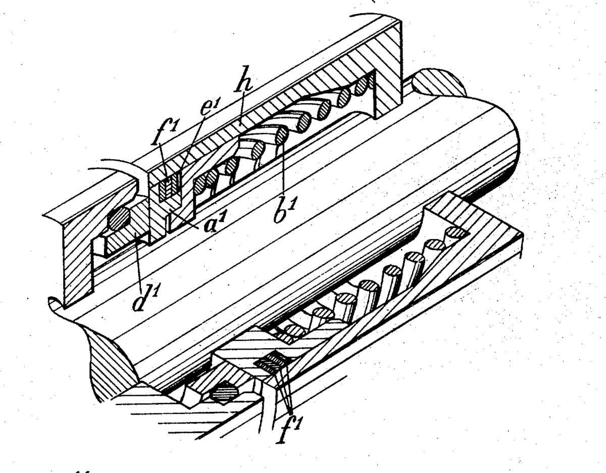
Elements d1 and a1 bear and slide on each other, creating a seal at their interface. One group of parts is connected to the rotating shaft and the other to the machine"s case. The spring keeps the elements tight against each other, maintaining the seal and allowing for wear.
An end-face mechanical seal, or a mechanical end-face seal, also referred to as a mechanical face seal but usually simply as a mechanical seal, is a type of seal used in rotating equipment, such as pumps, mixers, blowers, and compressors. When a pump operates, the liquid could leak out of the pump between the rotating shaft and the stationary pump casing. Since the shaft rotates, preventing this leakage can be difficult. Earlier pump models used mechanical packing (otherwise known as gland packing) to seal the shaft. Since World War II, mechanical seals have replaced packing in many applications.
An end-face mechanical seal uses both rigid and flexible elements that maintain contact at a sealing interface and slide on each other, allowing a rotating element to pass through a sealed case. The elements are both hydraulically and mechanically loaded with a spring or other device to maintain contact. For similar designs using flexible elements, see radial shaft seal (or "lip seal") and O-ring.
An end-face mechanical seal consists of rotating and stationary components which are tightly pressed together using both mechanical and hydraulic forces. Even though these components are tightly pressed together, a small amount of leakage occurs through a clearance that is related to the surface roughness.
The seal ring and mating ring are sometimes referred to as the primary sealing surfaces. The primary sealing surfaces are the heart of the end-face mechanical seal. A common material combination for the primary sealing surfaces is a hard material, such as silicon carbide, ceramic or tungsten carbide and a softer material, such as carbon. Many other materials can be used depending on pressure, temperature and the chemical properties of the liquid being sealed. The seal ring and mating ring are in intimate contact, one ring rotates with the shaft and the other ring is stationary. Either ring may be rotating or stationary. Also, either ring may be made of hard or soft material. These two rings are machined using a process called lapping in order to obtain the necessary degree of surface finish and flatness. The seal ring is flexible in the axial direction; the mating ring is not flexible.
By definition, the seal ring is the axially flexible member of the end-face mechanical seal. The design of the seal ring must allow for minimizing distortion and maximizing heat transfer while considering the secondary sealing element, drive mechanism, spring and ease of assembly. Many seal rings contain the seal face diameters, although this is not a requirement of the primary ring. The seal ring always contains the balance diameter.
The shape of the seal ring may vary considerably according to the incorporation of various design features. In fact, the shape of the seal ring is often the most distinct identifying characteristic of a seal.
By definition, the mating ring is the non-flexible member of the mechanical seal. The design of the mating ring must allow for minimizing distortion and maximizing heat transfer while considering ease of assembly and the static secondary sealing element. The mating ring can contain the seal face diameters, although this is not a requirement of the mating ring. To minimize primary ring motion, the mating ring must be mounted solidly and should form a perpendicular plane for the primary ring to run against. Like seal rings, mating rings are available in many different shapes.
Secondary sealing elements are gaskets which provide sealing between the seal ring and shaft (or housing) and the mating ring and shaft (or housing). Typical secondary sealing elements include O-rings, wedges or rubber diaphragms. The secondary sealing elements (there may be a number of them) are not rotating relative to one another. The secondary sealing element for the mating ring is always static axially (although it may be rotating). Secondary sealing elements for the seal ring are described as being either pusher or non-pusher in the axial direction. The term pusher is applied to secondary seals that must be pushed back and forth by the movement of the shaft or primary ring whereas non-pusher secondary seals are static and associated with bellows seal rings.
In order to keep the primary sealing surfaces in intimate contact, an actuating force is required. This actuating force is provided by a spring. In conjunction with the spring, axial forces may also be provided by the pressure of the sealed fluid acting on the seal ring. Many different types of springs are used in mechanical seals: single spring, multiple springs, wave springs, and metal bellows.
The term "hardware" is used to describe various devices which hold the other components together in the desired relationship. For example, a retainer might be used to package the seal ring, secondary sealing element and springs into a single unit. Another example of hardware is the drive mechanism which is necessary to prevent axial and rotational slippage of the seal on the shaft.
There are a number of different ways in which “seals” may be classified. Sometimes a reference to a “seal” may be to a sealing system whereas other times the reference is to a device such as a gasket, an O-ring, compression packing, etc. In this article, the reference is to an end-face mechanical seal.
One such method of classification considers design features or the configuration in which these features may be used. Classification by Design accounts for the details and features incorporated into a single seal ring/mating ring pair. Classification by Configuration includes the orientation and combination of the seal ring/mating ring pair.
In general, design features are not completely independent; that is, emphasis of a particular feature may also influence other features. For example, selection of a particular secondary sealing element may influence the shape of the seal ring.
The most common seal face design is a plain, flat, smooth surface but there are many special treatments intended for specific applications. The most common objective for the face treatment is to reduce the magnitude of mechanical contact. In general, face treatments provide a means of modifying the pressure distribution between the seal faces through hydrostatic or hydrodynamic topography. Seal face topography refers to the three dimensional aspects of the seal face surface.
In addition to the spring force, the seal faces are pushed together through pressure acting hydrostatically on the geometry of the seal. The ratio of the geometric area tending to close the seal faces to the area tending to open the seal faces is called the balance ratio.
Pusher seals employ a dynamic secondary sealing element (typically an O-ring) which moves axially with the seal ring. Bellows seals employ a static secondary seal (such as an O-ring, high temperature graphite packing, or elastomeric bellows and axial movement is accommodated by contraction or expansion of the bellows.
In addition to retaining the other components, the seal hardware includes the drive mechanism which is necessary to prevent axial and rotational slippage of the seal on the shaft. The drive mechanism must withstand the torque produced by the seal faces while also allowing the seal ring to move axially. In addition to torque, the drive mechanism must withstand the axial thrust produced by hydrostatic pressure acting on the components. The various types of drive mechanisms include: dent drive, key drive, set screws, pins, slots, snap rings and many more. Typically, the retainer for the seal ring might include set screws, a dent or slot drive, recesses for the spring and a snap ring to complete the assembly. In contrast, mating ring hardware might be only a pin or slot to prevent rotation. Corrosion is a major consideration when selecting seal hardware.
Both the seal ring and mating must accommodate secondary sealing elements. In some designs, various retainers, sleeves and other components may also include secondary sealing elements. Whereas a simple O-ring might require only a groove for fitting, some secondary sealing elements (for example, packing) might require mechanical compression. Although O-rings are available in many elastomers, sometimes an elastomer might not be compatible with the fluid being sealed or might be considered too expensive. In such cases, a secondary sealing element might be manufactured from perfluoroelastomer and shaped in the form of a wedge, V or U.
Although all end-face mechanical seals must contain the five elements described above, those functional elements may be arranged or oriented in many different ways. Several dimensional and functional standards exist, such as API Standard 682 - Shaft Sealing Systems for Centrifugal and Rotary Pumps, which describes the configurations for used in Oil & Gas applications. Even though the scope of API 682 is somewhat limited, it may be extended to describe end-face mechanical seals in general.
Configuration refers to the number and orientation of the components in the end-face mechanical seal assembly. For example, springs may be rotating or stationary. Single or multiple pairs of sealing faces may be used. For multiple seals, the individual pairs of sealing faces may be similarly oriented or opposed. Containment devices such as bushings may or may not be used as part of the configuration.
The basic components of an end-face mechanical seal may be installed directly onto the shaft but a popular approach is to pre-assemble the components into some sort of package for ease of installation.
Either the seal ring or the mating ring may be the rotating element. Seals with rotating seal rings are said to be "rotating" seals; seals with stationary seal rings are said to be "stationary" seals. Because the springs are always associated with the seal rings, sometimes the distinction is made as "rotating springs" versus "stationary springs". For convenience, rotating seals are used in most equipment; however, stationary seals have some advantages over rotating seals. In small, mass-produced seals for modest services, the entire seal may be placed in a package which minimizes shaft and housing requirements for the equipment. Stationary seals are also used to advantage in large sizes or at high rotational speeds.
When classifying end-face mechanical seals by configuration, the first consideration is whether there is only one set of sealing faces or multiple sets. If multiple sets are used, are the sets configured to be unpressurized or pressurized.
A tandem seal consists of two sets primary sealing surfaces with the space in-between the two seals filled with a compatible low pressure fluid called the buffer fluid. This buffer fluid/space may be monitored to detect performance of the assembly. Unfortunately, the definition of “tandem seal” was often stated in a confusing manner. In particular, a tandem seal was usually described as two seals pointing in the same direction; that is, in a face-to-back orientation. This orientation is not necessary to the function of the configuration and the API chose to use the term Arrangement 2 instead of tandem in the API 682 standard.
A double seal consists of two sets primary sealing surfaces with the space in-between the two seals filled with a compatible pressurized fluid called the barrier fluid. This barrier fluid/space may be monitored to detect performance of the assembly. Unfortunately, the definition of “double seal” was often stated in a confusing manner. In particular, a double seal was usually described as two seals pointing in the opposite direction; that is, in a back-to-back orientation. This orientation is not necessary to the function of the configuration and the API chose to use the term Arrangement 3 instead of double in the API 682 standard.
An end-face mechanical seal generates heat from rubbing and viscous shear and must be cooled to assure good performance and reliable operation. Typically, cooling is provided by circulating fluid around the seal. This fluid, known as a flush, may be the same as the fluid being sealed or an entirely different fluid. The flush may be heated, filtered or otherwise treated to improve the operating environment around the seal. Collectively, the flush and treating systems are known as piping plans. Piping plans for mechanical seals are defined by American Petroleum Institute specification 682 and are given a number. Some piping plans are used for single seals and some only for multiple seals. Some piping plans are intended to provide a means of monitoring the seal. Some sealing systems include more than one piping plan. See the table below for a summary and description of piping plans.
The first commercially successful mechanical seal to be used on centrifugal pumps was probably made by the Cameron Division of the Ingersoll-Rand Company. The Cameron seal was installed in a number of centrifugal pipeline pumps in 1928.
Mechanical seals in the 1930s often used a face combination of hardened steel versus leaded bronze. Carbon-graphite was not widely used as a seal face material until after World War II. Soft packing was used as secondary sealing elements. The O-ring was developed in the 1930s but not used in mechanical seals until after World War II.
In the late 1930s, probably about 1938 or 1939, mechanical seals began to replace packing on automobile water pumps. The famous Jeep of WWII used a rubber bellows seal in the water pump. After WWII, all automobile water pumps used mechanical seals.
In the mid-1940s pump manufacturers such as Ingersoll-Rand, Worthington, Pacific, Byron Jackson, United, Union and others began to make their own mechanical seals. Eventually most of these companies got out of the seal business but the Byron Jackson seal became the Borg-Warner seal (now Flowserve) and the Worthington seal was sold to Chempro (now John Crane - Sealol).
Cartridge seals were used on a regular basis by 1950; this convenient packaging of seal, sleeve and gland was probably developed by C. E. Wiessner of Durametallic about 1942.
By 1954, mechanical seals were used with such regularity in the refining and process industries that the American Petroleum Institute included seal specifications in the first edition of its Standard 610, "Centrifugal Pumps for General Refinery Services".
By 1956, many of the conceptual designs and application guidelines that are in use today had been developed. Commercially available designs included both rotating and stationary flexible elements, balanced and unbalanced hydraulic loading, rubber and metal bellows, and a wide variety of spring designs and types. Secondary sealing elements included O-rings, wedges, U-cups and various packings. Carbon-graphite was widely used as a seal face material; the mating seal face was often cast iron, Ni-resist, 400 series stainless steel, Stellite or aluminum oxide although tungsten carbide was coming into use. Stainless steel was widely used for springs, retainers, sleeves and glands. Single and multiple seal arrangements were used as necessary to accomplish the required performance. In 1957, Sealol introduced the edge welded metal bellows seal. Previously, metal bellows seals had used a formed bellows which was much thicker and stiffer.
In 1959, John C. Copes of Baton Rouge, LA filed for a patent on a split seal and was awarded Patent #3025070 in 1962. In the Copes design, only the faces were split. Copes chose to provide custom split seals which he manufactured himself so very few of his split seals were produced.
The Clean Air Act of 1990 placed limits on fugitive emissions from pumps. Seal manufacturers responded with improved designs and better materials. In October, 1994, the American Petroleum Institute released API Standard 682, "A Shaft Sealing Systems for Centrifugal and Rotary Pumps”. This standard had a major effect on the sealing industry. In addition to providing guidelines for seal selection, API 682 requires qualification testing by the seal manufacturers.
Today, in addition to face patterns such as spiral grooves and waves, materials have been developed that have special surfaces to promote hydrodynamic lift. Lasers can be used to etch microscopic, performance enhancing textures on the surface of the seal face. Piezoelectric materials and electronic controls are being investigated for creating truly controllable seals. The application of specialized seal face patterns, surfaces, and controls is an emerging technology that is developing rapidly and holds great promise for the future.
API Standard 682, Fourth Edition, 2014, “Pumps – Shaft Sealing Systems for Centrifugal and Rotary Pumps,” American Petroleum Institute, Washington D.C.
Schoenherr, K. S., "Design Terminology for Mechanical End Face Seals", Society of Automotive Engineers Transactions, Vol. 74, Paper Number 650301, (1966).
Buck, G. S., Huebner, M. B, Thorp, J. M., and Fernandez, C. L. “Advances in Mechanical Sealing – An Introduction to API-682 Second Edition”, Texas A&M Turbomachinery Symposium, 2003.
The exclusive face pattern contains special shallow grooves to provide both hydrostatic and hydrodynamic lift of the seal faces resulting in reduced energy consumption during ...
Single mechanical seal, balanced, independent of the direction of rotation with multi-spring configuration. The MTM180 Series represents the mechanical seal with the ...
... dual unpressurized arrangement, without outboard seals also incorporating the same non-pusher technology, the seal can be configured to suit both the operator and pipeline needs.
The AESSEAL® API Type A, B and C single-seal range offers the user an unprecedented range of API engineered sealing solutions to suit all application ...
Metal encased, rubber bellow seals to full DIN24960 (EN12756)L1K compatibility. The Stramek seal face is retained to avoiddamage during seal installation.
... 10T TS 10R Our Mechanical seal model TS10T TS10R can replace John Crane 10R 10T. 10T is integral rotary face ,10R is insert rotary face Operating Limits Pressure: 1.3MPa ...
Fluid motion systems rely on pumps and valves for regulating flow control inside and outside the system boundary, such as the casing of the pump or valve. A unique challenge in shaft-driven equipment is maintaining a dynamic sealing interface — one that prevents fluid from exiting the system while still allowing rotational motion between the shaft and the system boundary. End face mechanical seals have proven to be an effective way to solve this engineering.
Early pump models created a seal in one of two ways: 1) packing pliable rings around the shaft and compressing them into a seal housing until they contacted the shaft; 2) filling the seal housing with multiple bushings with close clearances over the shaft. Both methods create a sealing flow restriction along the equipment shaft, utilizing the shaft as a key part of the dynamic sealing interface.
With these designs, the amount of flow through the sealing interface — and the potential for process emissions — is proportionate to the size of the sealing interface gap. Since wear occurs as the shaft rotates and rubs inside these stationary radial sealing devices, process emissions are likely to increase as material wears away and expands the sealing interface gap. As a result, radial sealing methods are characterized by inadequate process emissions control and high rates of equipment wear, power consumption and maintenance time requirements.
Increasing concerns about plant efficiency, equipment life and excess process emissions necessitated a reliable sealing solution that did not use the equipment’s shaft for the dynamic sealing interface. The introduction of end face mechanical sealing was the answer to this problem. This method consists of two primary components:
1. A pair of seal rings, one attached to the rotating shaft and one fixed to the stationary body of the equipment, effectively moves the dynamic sealing interface from the equipment shaft surface to the mating face ends of the two rings. This establishes a planar, rather than annular, sealing interface.
2. Secondary sealing elements (i.e., O-rings) are then set to form a seal between the equipment and the seal rings. A spring is also added to push one ring against the other to compensate for face wear.
Together, these components comprise the essential elements of axial-sealing, end face mechanical seals. By significantly reducing the sealing interface area and narrowing the interface gap, end face mechanical seals give operators an effective means to control process emissions.
Another measure of the effectiveness of end face mechanical seals is their ability to be engineered and optimized for specific process applications. Through manipulation of seal ring geometry and the mechanical properties of different seal ring materials, the seal rings and ultimately the sealing interface can be controlled down to 10 microinches (0.25 micrometers) of sealing gap. In comparison, packing and bushing seals operate with a sealing gap in the range of 0.0001–0.010 inches (2.5–250 micrometers). This means that end face mechanical seals operate at a sealing gap 10–100 times narrower, and as such, provide a significant reduction in process emissions.
Continued advancements in end face mechanical seal design — in the areas of construction materials, seal ring tribological pairing, sealing interface topography, and component interface design and control — allow for increased optimization of the sealing interface gap. Modern analytical techniques are leading to the adoption of end face mechanical seal installations in more diverse applications, including: dry gas, ultra-high speeds (>10 000 RPM) and high pressures (>2000 psi or 137.9 bar). This specialization of end face mechanical seals has resulted in sealing solutions capable of minimizing process emissions to parts per million (PPM) levels over years of service — while requiring little to no maintenance of the seal.

Clark Seals Ltd. was contacted by the largest manufacturer of commercial laundry equipment with a problem they were having with seals leaking in sandy environments. Sand was getting between the sealing surfaces of the mechanical seal, grooving the face and causing leakage.
To solve the problem, we designed a custom two-piece integrated sealing solution that sealed against the top and bottom of the tub. The top seal was designed to press-fit around the tub bearing to improve alignment between the transmission, tub and agitator and a triple sealing lip to prevent water, sand and debris from entering the bearing cavity. The bottom seal was designed with a locking pin to resist torque and press-fit into the top seal during installation. To further reduce sand and other contaminants, our engineers developed and patented a unique negative "R"; sealing lip geometry that allowed the sprung lip to perform as an excluder lip and keep all sand out of the sealing environment.
The end result was a patented sealing solution that eliminated warranty claims, cost 80% less and lasted more than 700% longer than the mechanical seal it replaced.

Mechanical shaft seals are the best way to seal a pump. Face seals prevent leakage better than packing and if selected properly will last longer. Mechanical seals used in clean well lubricated applications can last 20 years. Seals can be constructed in single or double configurations, allowing only a vapor to escape.
Shaft seals are engineered forshaft-sealingapplications to serve Original Equipment Manufacturers or field replacement requirements, our seals will hold up to difficult applications. We can also asset in theconversion from braided pump packing to a mechanical seal.
American Seal and Packing delivers a full range of rotary mechanical seals configurations and component materials - to handle pump service requirements in a wide range of industries. . When you Specify a AS&P seals you have the advantage of proven reliability. When we need engineered seals for difficult applications we utilize the engineering departments of some of the top mechanical seal manufacturersin the world.

An end face mechanical seal is a device intended to prevent or minimize leakage from a vessel through the clearance around a rotating shaft entering that vessel. Perhaps the most common example is the end face mechanical seal used in the water pump of an automobile engine. Most pumps used in petroleum refineries, chemical plant and pipelines also use end face mechanical seals.
The simplest possible mechanical end face seal consists of a shoulder on a rotating shaft which rubs against a stationary case. This concept is shown in Figure 3.
As with packing or any bearing material, lubrication and cooling are required to prevent heat buildup and wear. Hydraulic pressure tends to force fluid between the faces and provide a lubricating film but the face separation must be kept very small to minimize leakage. Cooling is provided by the surrounding liquid. The conceptual design shown in Figure 3 is very simple, but it demonstrates the basic principle of the end face mechanical seals. Of course, it has functional drawbacks which must be addressed.
A major shortcoming of the conceptual design shown in Figure 3 is that there will be always be some shaft movement during operation of the equipment. This movement is a result of manufacturing tolerances, vibration, hydraulic forces and wear. Shaft movement may either decrease face separation, causing gross face contact and wear, or increase face separation, causing increased leakage.
Seal face leakage is governed by many variables, but the dominant variable is face separation. A variation of a few micro-inches (millionths of an inch) in the face separation can cause significant changes in leakage. Unfortunately, shaft movement can amount to several thousandths of an inch.
A practical approach to overcoming shaft movement is to mount one of the seal faces in a flexible manner so that it can move axially. Obviously a desirable feature, this flexibility is a prerequisite for effective seal design.
Figure 4 shows an improved seal as compared to Figure 3. In Figure 4, The sealing shoulder on the shaft has been removed and replaced with a component which is not permanently attached to the shaft. This component is called the primary ring. The “face” of the primary ring rubs against the mating ring. Since the primary ring and the shaft are two separate parts, an additional sealing device must be used to prevent leakage between the shaft and primary ring. The flexibly mounted primary ring can compensate for the small variations in movement on the axial plane. It can also adjust for seal face wear. Figure 4 is a very simple mechanical seal but it illustrates the concept used by the majority of mechanical seals. Of course, some additional components are required to preload the faces, transmit torque and provide ease of installation.
Figure 5 shows a more complete mechanical seal including a replaceable mating ring, “O-ring” gaskets, springs, setscrews and various other hardware. As will be seen later, the design of these components may vary considerably according to the required service for the seal. In addition, the assembled components themselves may be arranged and oriented in various ways to accomplish varying degrees of sealing, reliability and redundancy.
In a mechanical seal, the primary leakage path is between the seal faces. Naturally, increasing the face separation increases the leakage. In fact, as will be shown later, doubling the face separation can increase the leakage rate by a factor of eight! This relationship between leakage and face separation provides a powerful incentive for minimizing face separation. In modern mechanical seals, face separations are so small (on the order of a few microns) that the leakage rate is affected by the surface roughness. The effective face separation is a combination of the surface roughness of the two mating parts and the fluid film thickness. This concept is illustrated in Figure 6. The seal manufacturer can control the initial surface finish by lapping and polishing. A typical seal face is flat to within 23 millionths of an inch. This degree of flatness is so small that refracted light rays must be used to measure it. The fluid film is established during initial start-up of the seal by hydraulic forces.
The principle of establishing a fluid film is essential to all seal designs. Most mechanical seals are designed to operate in liquids; these seals require a liquid film. Designing a seal to operate on a gas film is much more complex. Whether the film is gas or liquid, it reduces the gross contact between the rotating component and the stationary component. It also provides lubrication to reduce friction and wear. Without a stable fluid film, gross rubbing contact could damage the faces.
Mechanical seals may be classified by their design features and the arrangement of those features. The Design category includes the details and features incorporated into a single primary ring/mating ring pair. The Arrangement category includes the orientation and combination of the primary ring/mating ring pair. Figure 7 illustrates the classification of mechanical seals.
The Design classification considers the details which enter into the features of these components. Some examples of these features are balance, face treatment, rotating element, springs, secondary sealing elements and drive mechanism. In general, these design features are not completely independent; that is, emphasis of a particular feature may also influence other features. For example, selection of a particular secondary sealing element may influence the shape of the primary ring.
By definition, the primary ring is the flexible member of the mechanical seal. The design of the primary ring must allow for minimizing distortion and maximizing heat transfer while considering the secondary sealing element, drive mechanism, spring and ease of assembly. Many primary rings contain the seal face diameters, although this is not a requirement of the primary ring. The primary ring always contains the balance diameter.
Balance. The term “balance” is frequently referred to as the relationship of hydraulic forces on a seal but it is actually a geometric ratio. Balance ratio is defined as the ratio of the hydraulic closing area to the hydraulic opening area. This ratio is customarily expressed in a percentage.
Figure 8 illustrates the concept of balance. In a seal, hydraulic pressure acts on the back of the primary ring; the resulting force pushes the faces together. This force is called the closing force and this area the closing area. Similarly, any pressure between the seal faces creates an opening force which tends to separate the faces. Therefore, the face area is also called the opening area. The balance ratio is simply the ratio of the closing area to the opening area.
As shown in Figure 8, the area above the seal face outside diameter is disregarded when the closing area is computed. This area is not considered because the pressure is the same all around it; consequently the contribution of the resultant of the hydraulic forces on this area is zero.
When the closing area is reduced, the closing force is reduced proportionally; this feature can be used to advantage when designing a seal. However, for a seal shape such as shown in Figure 8, the closing area will always be greater than the opening area. In order to make the closing area less than the opening area, the shape can be changed as shown in Figure 9.
The seal shown in Figure 8 is said to be an “unbalanced” seal. Its balance ratio is greater than 100% because of the necessary clearance underneath the mating ring. Typical balance ratios for unbalanced seals range from 120 to 150%. The seal shown in Figure 9 is said to be a “balanced” seal; its balance ratio is less than 100%. The balance ratio of “balanced” seals is typically from 65% to 90%.
The distinction between “balanced” seals and “unbalanced” seals is simply that balanced seals have a balance ratio less than 100%. A seal with 99% balance ratio is balanced, a seal with 101% balance ratio is unbalanced.
For a given pressure, balanced seals have less face load than unbalanced seals. Therefore, balanced seals are normally used in higher pressures than unbalanced seals.
Primary ring shape.The shape of the primary ring may vary considerably according to the incorporation of various design features. In fact, the shape of the primary ring is often the most distinct identifying characteristic of a seal. Figure 10 shows four examples of typical primary ring shapes.
Figure 10a represents a primary ring associated with elastomeric bellows seals. This primary ring has been optimized to take advantage of the elastomeric bellows and a large, single spring.
Figure 10b represents a primary ring with an inserted seal face. Insert faces must be designed with care because temperature differentials can cause differential expansion between the adaptor and the primary ring. Insert designs can also have problems associated with mechanical stress and distortion.
Figure 10c and 10d show how the shape of the primary ring is influenced by the secondary sealing element. Figure 10c is a primary ring designed to work with a wedge. Figure 10d is designed to work with an O-ring. Also, Figure 10c shows an unbalanced shape while Figure 10d is a balanced shape.
Face Treatment.The most common seal face design is a plain, flat surface but there are many special treatments designed for specific applications. Figure 11 shows some of the more common face treatments. The plain, flat face is most common. In general, face treatments are a means of modifying the pressure distribution between the seal faces. The most common objective is to increase the opening force and thereby reduce the magnitude of the mechanical contact. Face treatments may be considered to produce hydrostatic or hydrodynamic forces.
The simplest face treatment is a plain face that is not flat. This design produces forces that are primarily hydrostatic. Figure 11b shows an example of a face that is lapped so that it tends to touch the mating ring at the inside diameter. This means that the leakage path is converging. Although this is a simple concept, it is actually difficult to lap the required taper with the desired accuracy. Too little taper will allow some rubbing to occur at the ID which will change the taper. Too much taper will cause gross separation of the faces with the resulting high leakage.
Figure 11c shows another type of hydrostatic face treatment — the hydropadded face. Hydropads are recesses which are machined into one face — usually the face with the softer material. After machining the recesses, the remainder of the face is lapped flat. The size, quantity and location of the hydropads is such that the faces still rub; therefore, leakage is low. The depth of the hydropads is sufficient to allow for long life in spite of the rubbing. Hydropads actually show some slight hydrodynamic effects, especially in viscous liquids.
Rotating Element. Although most illustrations have shown the primary ring to be rotating with the shaft, either the primary ring or the mating ring may be used as the rotating element. Seals with rotating primary rings are said to be “rotating” seals; seals with stationary primary rings are said to be “stationary” seals. Because the springs are always associated with the primary rings, sometimes the distinction is made as “rotating springs” versus “stationary springs”.
For convenience, rotating seals are used in most equipment. Pump shafts are already made of a comparatively high grade material and manufactured to close tolerances. This makes pump shafts well suited for rotating seal applications. Assembly of rotating seals can generally be done directly on the shaft or by using a relatively simple sleeves. Figures 5, 8 and 9 all show rotating seals with stationary mating rings.
Stationary seals have some advantages over rotating seals. In small, mass produced seals for modest services, the entire seal may be placed in a package which minimizes shaft and housing requirements for the equipment. Figure 13 shows a low cost stationary seal. Stationary seals are also used to advantage in large sizes or at high rotational speeds. Above 5,000 to 6,000 fpm, a rotating primary ring (which is flexible, by definition) may require dynamic balancing (for rotational imbalance) in order to operate in a stable mode. A stationary primary ring does not require this balancing. On the other hand, the stationary seal does require a close bore tolerance. This close bore tolerance is usually a second manufacturing operation on most equipment. Stationary seals sometimes incorporate special design features such as auxiliary liners, sleeves or adapters to help retain the mechanical advantages of the seal. Figure 14 shows a stationary metal bellows seal used in high temperature centrifugal pumps.
By definition, the mating ring is the non-flexible member of the mechanical seal. The design of the mating ring must allow for minimizing distortion and maximizing heat transfer while considering ease of assembly and the static secondary sealing element. The mating ring can contain the seal face diameters, although this is not a requirement of the mating ring. To minimize primary ring motion, the mating ring must be mounted solidly and should form a perpendicular plane for the primary ring to run against. Figure 15 shows some typical mating rings.
Floating. Figure 15d is the floating ring type. This design offers the flexibility of using teflon, grafoil, or an O-ring (Figure 15c) for the secondary sealing item. If teflon or grafoil is used, a pin should be added to prevent rotation due to the low coefficient of friction of these materials.
Cup Mount.Figure 15e, the cup-mounted construction, offers a low-cost arrangement which can be used with surface finishes over 63 rms. It is limited on high temperature applications and to lower pressure ranges because of the insulation effect of the cup.
The secondary sealing elements are gaskets which provide sealing between the primary ring and shaft (or housing) and the mating ring and shaft (or housing). They are called secondary sealing elements because their leakage path should be secondary to the seal face leakage. Loading by hydraulics or mechanical force makes the secondary seal tight in its confined area. The secondary sealing element for the mating ring is always static axially (although it may be rotating). Secondary sealing elements for the primary ring are described as being either pusher or non-pusher in the axial direction. The term pusher is applied to secondary seals that must be pushed back and forth by the movement of the shaft or primary ring. A non-pusher secondary seal is a static seal for the primary ring.
Pusher type secondary seals have the disadvantage of damaging the surface to which they must seal. This damage, called fretting, is caused by the cyclic movement of the secondary sealing element as the shaft rotates. In contrast to the pusher design, a non-pusher secondary sealing element could not cause any fretting.
On the other hand, this rubbing and dragging effect is also an advantage of the pusher design because it adds damping and therefore stability to the seal. This damping can make a significant difference in performance for some services.
Figure 16 shows examples of pusher, non-pusher and static secondary seals. The pusher design may use O-rings, wedges, etc. The non-pusher is always some sort of bellows with a static section. Mating rings use various static gasketing and O-ring designs.
Bellows. Figure 16a is a full convolution elastomeric bellows. It offers the greatest possible flexibility to the front section of the primary ring. The front section of this bellows has minimum contact with the shaft or sleeve, thus minimizing wear and hang-up. The large tail section provides a considerable sealing area to compensate for imperfections in the shaft. There are also are variations of the full convolution design that use a half convolution. Its ability to accept axial motion is reduced, due to the one-half convolution design.
Figure 16b is a bellows made out of teflon or glass-filled teflon combinations. This seal which is designed for the extremes of corrosive environments, provides the advantages of the non- contacting bellows convolution. Because it is made out of teflon, support rings or a drive collar is required to attach the tail section or the bellows to the shaft. Due to the requirements of flexibility, the convolutions must be considerably larger in cross-section than the typical elastomeric bellows design.
Figure 16c is an all-metal bellows style seal. It has the inherent advantage of flexibility associated with bellows design for high temperature applications. Due to its all-metal construction, it offers considerable freedom of design since it is not restricted to the temperature and chemical limits of elastomers. Metal bellows are constructed of individually welded metal leaves approximately .004/.012 thick. A large number of leaves are required to provide the maximum amount of flexibility associated with other styles of bellows seals. The mechanical closing force that is provided by the spring on other seal designs is accomplished by stressing the bellows from free height in this design. Metal bellows seals are inherently balanced because of the manner in which the bellows becomes distorted when pressurized.
“V” Rings, “U” Cups and Wedges. Figure 16d is a wedge. Wedges are typically made of TFE material. They are considerably more flexible than the “V” ring or U-cup arrangement because they operate on the ball-and socket principal. Special manufacturing fits are not a requirement for wedges because of the shallow angle of contact between the primary ring and the shaft. However, it does require a polished surface for effective sealing (32 rms with polish).
In addition to wedges, there are U cups and V rings. Their construction as a secondary seal offers limited amounts of flexibility and requires extremely close tolerances on the cross-section fits. The “V” rings are generally manufactured in TFE or TFE-filled material, requiring pre-loading of the rings to activate the point contact on the lips. Because of the “V” ring design, it can be used at high pressures but it is the least flexible, and most rigid of the secondary seal designs. Because of it’s construction, the “V” ring cannot flex to compensate for motion and it must be pushed along the shaft to take up wear at the seal faces. Shaft and primary ring finish must be highly polished (15 rms) in order for this type of secondary seal to operate leak-free.
O-Rings. Figure 16e is the O-ring. This is by far the simplest and most popular secondary sealing element. It has been used successfully over a wide temperature range and in a variety of fluids. O-rings are considered to be self-energizing seals and do not require much mechanical preloading. This feature allows O-rings to be used at very high pressures. O-rings are offered in a complete range of chemical resistant and general service compounds. Buna-N, Neoprene, Ethylene-Propylene, Viton, and Kalrez are typical materials selected for a variety of service conditions. On the other hand, Teflon does not make a good O-ring material, particularly if the O-ring is to be dynamic.
There are encapsulated O-rings. This is an attempt to obtain the chemical resistance offered by Teflon and the flexibility of the elastomeric O-ring. Unfortunately, the result is dominated by the hardness of the Teflon outer shell. The recommended surface finish of the shaft/sleeve is 15 rms. The encapsulated “O” ring is sensitive to temperature fluctuations. Because of these limitations, encapsulated O-rings are usually recommended only for static sealing.
In every mechanical seal there is always a need for keeping the faces closed in the absence of hydraulic pressure. Generally, a mechanical device in some form of spring is used. Figure 17 shows some of the different types of springs used in mechanical seals.
Single spring.A single spring seal has the advantage of comparatively heavy cross section coil which can withstand a higher degree of corrosion. Another advantage is that single springs do not get clogged by viscous liquids. The disadvantage of a single spring is that it does provide uniform loading characteristics for the faces. Also, centrifugal forces may tend to unwind the coils. Single springs also tend to require more axial space and a specific spring size is required for each seal size.
Multiple springs.Multiple springs are usually smaller than single springs and provide a more uniform load at the faces. The same spring size can be used with many seal sizes by simply changing the number of springs that are used. Multiple springs resist unwinding from centrifugal force to a much higher degree than a single coil spring since the forces act differently. The most obvious disadvantage of small springs is the small cross section wire. This makes the smaller springs subject to corrosion and clogging.
Wave spring. The next form of spring generally considered is the wave type, simple described as a washer into which waves have been formed to provide a given amount of mechanical loading . The main reason for using this type of spring is that it requires even less axial space than the multiple spring design. On the other hand, special tooling must be made for best manufacturing results. Further, the tempering required on this design limits materials to those which are not as corrosion resistant as the high grade stainless and Hastelloy groups. Also, when using wave springs, a greater change in loading for a given deflection must be tolerated. That is, a great deal of force loss or force gain, with comparatively small axial movement must be expected.
Metal bellows. A metal bellows is actually a combination of a spring and secondary sealing element. Welded edge metal bellows resemble a series of Belleville washers. Formed bellows may be used to reduce the quantity of welding; however, a formed bellows has a much higher spring rate than a welded bellows. The bellows thickness must be selected for resistance to pressure without an excessive spring rate. The welding technique and bellows shape must be selected for maximum fatigue life.
The term “hardware” is used to describe the various devices which hold the other components together in the desired relationship. For example, a retainer might be used to package the primary ring, secondary sealing element and springs into a single unit. Another example of hardware is the drive mechanism which is necessary to prevent axial and rotational slippage of the seal on the shaft.
A drive mechanism is required because of the torque created between the seal faces. Both static and dynamic drives are required. The static drive is only required to hold an axial position and transmit torque. The dynamic drive must transmit torque and allow for the axial flexibility of the primary ring. Figure 18 shows some variations of drive mechanisms. Dedicated devices made of strong materials are said to be positive drives and are generally preferred in the heavy duty seals.
Key drive.This is one of the more rugged forms of drive. In high pressure, comparatively large size units, the ruggedness of this type of drive is in keeping with the balance of the sturdy features incorporated in seals for high pressure applications.
Set screws.This simple method of driving takes advantage of a common hardware item. Set screws are probably the most common type of static drive mechanism. They are not recommended for dynamic drive because the roughness of the threads can restrict axial flexibility of the primary ring.
Elastomer Drive.This is not a positive drive method and is generally limited to light duty seals; however, it is extremely simple, economical and effective for some services.
Spring drive.Another effective drive mechanism for light duty seals is to incorporate the drive into the springs. Care must be taken in this design as to the direction of rotation, corrosion rate and spring rate.
Although all end face mechanical seals must contain the five elements described above, those functional elements may be arranged or oriented in many different ways. Several dimensional and functional standards exist, such as API Standard 682 – Shaft Sealing Systems for Centrifugal and Rotary Pumps, which describes the configurations for used in Oil & Gas applications. Even though the scope of API 682 is somewhat limited, it may be extended to describe end face mechanical seals in general.
Configuration refers to the number and orientation of the components in the end face mechanical seal assembly. For example, springs may be rotating or stationary. Single or multiple pairs of sealing faces may be used. For multiple seals, the individual pairs of sealing faces may be similarly oriented or opposed. Containment devices such as bushings may or may not be used as part of the configuration.
Single seals. The vast majority of all seals fall into the single seal category. In this category the seal can be mounted so that it is inside the process liquid or outside the process liquid. Inside mounted seals are easier to cool and generally can seal higher pressures. Also the direction of leakage is opposed by centrifugal force. Inside mounted is by far the most popular, see Figure 19.
An outside seal is shown in Figure 20. Outside seals have minimal contact with the process liquid. This is an advantage in sealing corrosive liquids providing that overheating is not a problem. A disadvantage of outside seals is that the direction of leakage is the same as centrifugal force.
Multiple seals. Multiple seal arrangements can provide environmental controls and/or redundancy. The most common types of multiple seal arrangements were previously called double and tandem but are called Arrangement 2 and Arrangement 3 by API 682. The double seal emphasizes environmental controls while the tandem seal emphasizes redundancy.
The principal purpose of the tandem seal is to provide redundancy. The two seals are oriented so that the outer seal can accomplish the sealing task if the inner seal fails. A tandem arrangement is shown in Figure 21. Because of this redundancy, the outer seal is sometimes called the “backup” or “safety” seal. Tandem seals use a buffer fluid to lubricate and cool the outer seal. The inner seal operates in the process liquid and is cooled by that liquid. Any leakage from the inner seal must be contained by the outer seal and buffer system. The buffer fluid is normally at a pressure less than the stuffing box pressure. In order to keep the buffer pressure low, the buffer system is vented continuously.
Tandem seals (API Arrangement 2) are also used in “stages” (perhaps this is the origin of the name “tandem”) when process pressures are extremely high. When tandems are used in stages, the buffer system is pressurized to some intermediate pressure, typically half the stuffing box pressure.
The double seal (API Arrangement 3) uses two primary ring/mating ring pairs oriented so that a pressurized barrier liquid is maintained between them as shownin Figure 22. On double seals, the inner seal seals between the process liquid and the barrier liquid. Because the barrier system is at a greater pressure, any leakage is barrier liquid. The outer seal seals between the barrier liquid and the atmosphere. In most cases the barrier liquid is circulated and cooled to prevent heat buildup.
Notice that Figure 21 and 22 are identical. The only differences are the design of the faces and balance diameter and these details are not shown. This is somewhat controversial and many would describe both Figure 21 and 22 as being “tandem” because of the orientation of the components. Traditionally, a “double” seal would have the primary rings in a back-to-back orientation; however, for purposes of operation, either face-to-back (shown) or back-to-back may be used.
Figure 23 illustrates face-to-back, back-to-back and face-to-face orientations. Although Figure 23 shows rotating primary rings, the same concept and names applied to stationary primary rings.
The biggest problem with the double seals is maintaining the barrier liquid at a higher pressure than the stuffing box. It is generally recommended that a 20 psi or 10% differential in favor of the barrier be maintained at all times.
In the past, double seals were described as primary ring/mating ring pairs which faced in opposite directions. A classic double seal is shown in Figure 24. This is usually true but is not a requirement of the double seal arrangement. Similarly, a tandem arrangement was frequently described as seal pairs facing the same direction, see Figure 21. Again, this is not a requirement. In a tandem arrangement, the buffer fluid is at the lower pressure and is continuously contaminated by leakage of the product across the primary seal. In a double seal arrangement, the barrier fluid is at the higher pressure and the product fluid is continuously contaminated by leakage of the barrier fluid across the primary seal.
Double seals (API Arrangement 3) are used with API Piping Plans 53A, 53B, 53C or 54. Tandem seals (API Arrangement 2) are used with API Piping Plans 52and 55.
The term “adaptive hardware” is applied to hardware designed to simplify the incorporation of the primary ring and mating ring into the equipment which requires the mechanical seal. The most common examples of adaptive hardware are the sleeve and gland.
When the components are pre-assembled onto a sleeve and gland plate, the complete assembly is called a cartridge seal. This complete assembly can be easily slid onto the shaft and bolted in place thus reducing the potential for installation errors. Some cartridge seals use regular component seal parts whereas other cartridge seals might use specific purpose parts. API 682 specifies that only cartridge seals are acceptable to the standard.
Figure 23a shows the plain integral type gland plate which, if lapped on the sealing surface and gasketed perfectly to the face of the box without distortion, can serve as a sealing face against the rotating seal head. It is an item utilized on many compressor installations, showing that when applied correctly, even a gas such as Freon can adequately be sealed with this type of design. It becomes a desirable feature, especially where axial room is at a premium. It must be considered only where practical. If a relatively large bolt circle in relation to the shaft size is inherent in the unit, this design may prove uneconomical.
Figure 23b is a plain end plate with a pressed-in seat element. Some seal manufacturers advocate this design and it can be utilized where its stresses, replacement features and economics can be tolerated.
Figure 21c shows a so-called plain gland plate but with an O-ring seat added. Where the use of the integral gland plate is not practical from the standpoint of replacement cost or because the seat material itself must be of a higher grade material than it is practical for the endplate, this type of design becomes useful.
Still another auxiliary feature is termed the quench type gland plate. This gland type incorporates an entrance for liquid behind the seal face on the atmosphere side. Two other desirable features are to be gained from this quench gland-one is the safety provided by the throttling effect on the escaping liquid if the seal fails; the other relates to toxic liquids. If the liquid handled is toxic-instead of using the quench gland with a secondary liquid, the liquid can be vented to a safe area.
Sleeves are employed as an adapter from the seal requirements to the shaft requirements of the equipment. For example, the seal may require different diameters, as in a balanced seal. Figure 24 shows the two most common types of shaft sleeve.
Figure 24b is the “cartridge” or “package” sleeve. This design allows the complete seal, gland and sleeve to be assembled before it is installed in the pump.

[0003] When a fluid-containing housing, for example the housing of a pump or turbine, is penetrated by a rotating shaft, a mechanical seal is often used to minimize leakage of a process fluid from the interior of the housing. End face mechanical seals, also referred to as mechanical face seals, are commonly used for this purpose.
[0004] Mechanical seals rely on maintaining a closely spaced relationship between the flat and parallel surfaces of a stationary, "stator" seal face and a rotating "rotor" seal face. This generally requires that a lubricant or other
[0005] In circumstances where the process fluid is non-lubricating and/or hazardous, a separate, pressurized lubrication system is sometimes provided that introduces a liquid lubricant into the seal. The lubricant is applied with sufficient pressure to cause it to slowly leak through the seal into the process, thereby
preventing any escape of the process fluid through the seal into the surrounding environment. While this approach can be highly effective, it is also complex and expensive.
[0006] In situations where the process fluid is a liquid with suitable lubricating properties, the process liquid itself is often used as the seal lubricant by allowing the process liquid to enter the seal and slowly leak past the seal faces. This approach has the advantage of not requiring a separate, complex and costly lubrication system. However, this approach has the disadvantage that small amounts of process fluid is allowed to leak past the seal and into the surrounding environment, which may be unacceptable in cases where the process fluid is hazardous or otherwise undesirable.
[0007] Under such circumstances, one approach is to provide a second, "dry" mechanical seal in tandem with the primary seal that will intercept the slowly leaking process fluid and allow it to be recaptured without escaping into the environment. Such dry mechanical seals may be "lift-off seals, whereby the rotor and/or stator seal faces include lift-off features that create a pressurized air cushion during operation that fills the small gap between the two seal faces, thereby minimizing friction, wear, and heating. An example of this arrangement is shown in Figure 1 , which includes a primary mechanical seal 100 that is lubricated by the process liquid, arranged in tandem with a secondary, dry mechanical seal 102 that is lubricated by a cushion of air. This approach has the added advantage that the secondary, "dry" seal 102 can provide temporary backup sealing in the event that the primary seal 100 suddenly fails, giving the operator of the equipment enough time to invoke immediate shutdown and isolation
maintained in a standby mode, typically with its shaft spinning at a very low speed. Under such circumstances, the rotation speed while in stand-by mode may not be sufficient to enable a dry mechanical seal 102 such as the one illustrated in Figure 1 to generate a lubricating air cushion, thereby causing the seal to operate in stand-by mode with the stator and rotor faces in direct mechanical contact. This can lead to damage of the lift-off features on the rotor and stator seal faces, such that they are no longer able to generate a lift-off cushion even when they are subsequently switched to normal operating mode with high shaft operating speeds. As a result, the seal faces may remain in contact when they are subsequently operated at high rotational speeds, which will cause the faces to overheat and wear at a rapid rate.
[0009] What is needed, therefore, is a dry running mechanical seal design that is able to maintain the faces in direct contact for extended periods of time at both low and high operating speeds, without requiring a lift-off feature, and without undue heating or wear of the seal faces when the seal is operated at high shaft speeds.
[0010] A dry running mechanical seal design is disclosed that is able to maintain the faces in direct contact for extended periods of time at both low and high operating speeds without including a lift-off feature and without undue heating or wear of the seal faces when the seal is operated at high shaft speeds.
• the stator seal face is lapped on both the front and rear surfaces, and surfaces of the gland plate that make contact with the rear surface of the stator seal face are also lapped, thereby providing enhanced thermal contact between the gland plate and the rear surface of the stator seal face;
• enlarged cooling scallops or other surface features are provided on the front surface of the rotor seal face that increase circulation of air in the vicinity of the seal faces;
• the surface with which the dynamic rotor gasket or O-ring makes contact is highly polished, thereby minimizing frictional drag on the dynamic gasket or O-ring, reducing the required load of the springs that keep the two faces in contact, and thereby minimizing the frictional heat that is generated.
[0012] According to the present invention, heat transfer by direct physical contact from the stator seal face to the gland in which the stator seal face is mounted is enhanced by lapping of both the rear surface of the seal face and the contacting surfaces of the gland. In embodiments, these two surfaces are lapped to a flatness of flatter than three microns, and in some embodiments flatter than 1.5 microns. In various embodiments, the roughness of the lapped surfaces is less than 20 RMS, and in some embodiments less than 10 RMS, where RMS is used herein to refer to "root-mean-square" values measured in micro-inches. This improvement allows the gland to function as a virtual "heat sink" for the direct transfer of heat from the stator seal face.
[0013] In addition, an annular groove is formed in the gland plate that functions as a cooling annulus through which air can flow while the seal is in operation. In embodiments, slots provided in the gland plate connect the cooling annulus with the inner diameter of the gland plate, thereby allowing for entry of air into the annulus from a region surrounding the spinnin


 8613371530291