
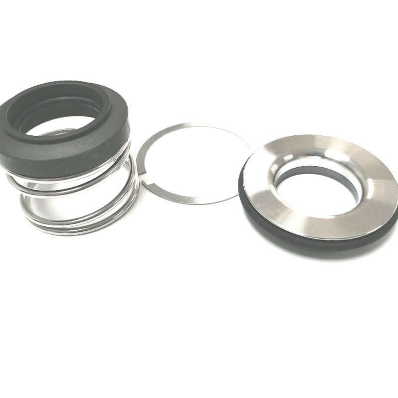
single mechanical seal free sample
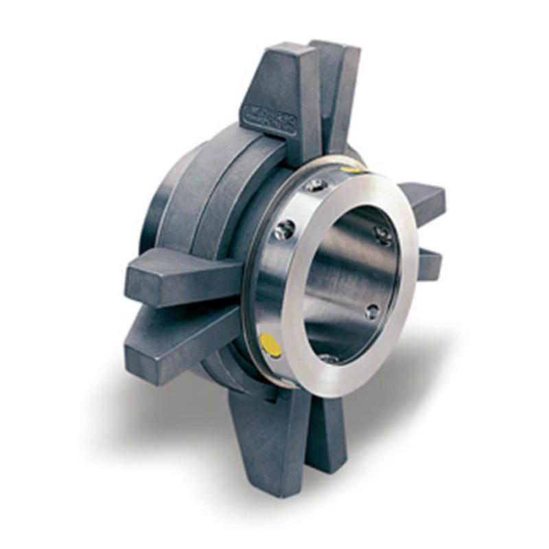
1.Blackmer mechanical seal 45mm is structural simple and reliable. It has a wide application scope.2. Mechanical seal 55mm is suitable for CNP pumps, often used for stainless steel vertical mulltistage centrifugal pump.3.Blackmer mechanical seal also can provide important material certifications available.
Lepuseal have more than20 years experienceinmanufacturing mechanical seal, we established astrong technology team include 20+ engineerR&D team, more than 150 skilled workers team, more than 10 person quality control team, that help us to provide strong technology support to our users.
Lepuseal have more than10000 square meters workshop and60+ advanced CNC machineto provide strong ability for production.And make sure we can offer fast delivery service to our clients.
A dry gas seal is a revolutionary way of sealing machines and protecting them from dust, moisture and other contaminants. A dry gas seal is a sealing device that uses pressurized gas to keep two surfaces from touching. The most common type of dry gas seal is the O-ring, which is used in many applications, including mechanical seals, piston rings, and gaskets. Dry gas seals are also used in many other industries, such as the food and beverage industry, where they are used to seal containers and prevent contamination. This type of seal not only helps to keep the machine running with maximum efficiency but also significantly reduce downtime, making it cost-effective in the long run. In this article, we"ll explore what a dry gas seal is, how it works and why you should consider using it for your machinery. By understanding the benefits of a dry gas seal and its uses, you can make an informed decision about the best sealing system for your needs. How does a dry gas seal work?Dry gas seals work by using a series of labyrinths to separate the high pressure seal gas from the atmosphere. The labyrinths are formed by a series of grooves and ridges on the surface of the seal ring. The seal ring is rotated at high speed, causing the gas to flow through the labyrinths. The gas is then forced through an aperture in the center of the seal ring, where it escapes into the atmosphere. What is a dry gas seal used for?Dry gas seals are used on rotating equipment to help minimize the leakage of high pressure gases from the inside of the machinery. This helps to reduce maintenance costs and improve safety. Dry gas seals are commonly used in applications such as pumps, compressors, turbines, and blowers. Advantages of a dry gas sealThere are many advantages of a dry gas mechanical seal. One advantage is that they are much simpler in design than other types of seals, making them more reliable and easier to maintain. Additionally, dry gas seals do not require the use of any lubricating fluids, which can leak or evaporate over time. This makes them more environmentally friendly and cost-effective in the long run. Finally, dry gas seals have a much longer lifespan than other types of seals, meaning that they need to be replaced less often.Disadvantages of a dry gas sealThere are several disadvantages of dry gas seals, including: - they can be expensive to purchase and install- they require careful maintenance and regular inspection- they can be susceptible to wear and tear- they can leak if not maintained properlyHow to choose the right dry gas seal for your applicationThere are a few key factors to consider when choosing the right dry gas mechanical seal for your application. The most important factor is the type of fluid being sealed. Gas seals are designed to seal either liquids or gases, but not both. Make sure to choose a gas seal that is compatible with the fluid you are sealing.Another important factor to consider is the pressure of the fluid being sealed. Gas seals are rated for different maximum pressures, so make sure to choose one that can handle the pressure of your application.Finally, take into account the size and shape of the sealing surfaces. Gas seals come in a variety of sizes and shapes to fit different applications, so make sure to choose one that will fit your needs.ConclusionDry gas seals are an extremely important component for many industrial operations, and their ability to prevent leaks has made them invaluable in a variety of applications. Understanding the basics of how dry gas mechanical seal work and how they can be used effectively is helpful when considering the various options available for any specific application. With the right choice, dry gas seals can provide reliable, leak-free performance which will save time, money and resources while ensuring safety and reliability. Lepu dry gas seal manufacturer provides best quality flowserve dry gas seal and dry gas seal. Welcome to contact us!

The global mechanical seals market size stood at USD 3.20 billion in 2018 and is projected to reach USD 4.77 billion by 2026, exhibiting a CAGR of 5.2% during the forecast period.
The key utility of a mechanical seal is to prevent leakage of fluids or gases through the clearance between the shaft and the container. Mechanical seals consist of a set of 2 faces separated by carbon rings. The first face is in contact with the rotating equipment whereas the second face is stationary. Moreover, the main part of the seal is the seal ring (first face) on which the mechanical force is acting, generated by springs, bellows, or fluids in the equipment. In recent years, mechanical seals are playing an important role in varied industrial applications, enabling efficient operations. Mechanical seals are made up of several flexible materials such as Polytetrafluoroethylene (PTFE), Polyurethane (AU, EU), industrial rubber, Fluorosilicone (FVMQ), and many more.
The mechanical seal market has depicted significant growth in the recent span of years and is likely to grow in the forecasted period. Rising industrial development in emerging economies is expected to initiate additional development policies and investments. Major types of mechanical seals available in the market include cartridge seals, balanced and unbalanced seals, pusher and non-pusher, and conventional seals that are influencing the mechanical sealing market growth in developing countries.
Growth in machine tool industry is impelling the overall market share, owing to the usage of power machines in centrifugal pumps and compressors for sealing and separating the fluid in the rotating shafts. Hence, the increasing market demand for mechanical seals in various industries is anticipated to drive the market growth in the near future. Furthermore, the highest market growth is projected to be witnessed in Asia-Pacific, followed by North America.
According to the United Nations Conference on Trade and Development (UNCTAD), the global foreign direct investment (FDI) will grow vigorously in 2018. This implies that there will be strong growth in the manufacturing sector in the coming decade. Moreover, many countries are now adopting investment policies that will boost the manufacturing sector and drive the mechanical seals market trends. For instance, in 2017, several countries and economies adopted investment policy measures across the globe, of which 84% of countries were favorable to investors. This will allow investors to invest their funds in various industries, with primary focus on energy, transportation, and manufacturing.
Therefore, the demand for manufacturing is increasing with the changes in investment policies of multiple developed and developing countries. This growth will increase the adoption of machine tools and industrial equipment for the manufacturing process, which will directly boost the mechanical seals market growth, globally.
The global mechanical seals market is segmented by type, which is further segmented into pusher and non-pusher, conventional seals, balanced and unbalanced seals, and cartridge seals.
Continuous adoption of advanced sealing material in several industries is expected to grow the cartridge seals segment in the forecast period. The cartridge seals segment is estimated to have exponential market opportunities as they are designed as universal shaft seals for the seal chamber of pumps, containers, or pipelines.
The pusher and non-pusher seals segment depicts substantial growth, owing to the increasing usage of small and large diameter ring shaft in the light end services to handle high temperatures. The balanced and unbalanced mechanical seals segment is anticipated to grow moderately, owing to the rise in the industry sector worldwide. Balanced seals are preferred for most of the industrial applications as they generate less heat at the surface of the machine, enabling longer seal life and efficient sealing method.
Comparatively, the conventional seal segment is projected to witness progressive growth owing to the requirement of heat exchanger mating ring advances offered by these seals. The other segment consists of bellows seals and is likely to represent steady growth due to limited demand in the mechanical sealing market.
Oil and gas industry is anticipated to grow exponentially at a higher growth rate owing to increasing demand of petroleum from developed and emerging countries, hence boosting the demand of mechanical seals. Energy utilization is growing worldwide and influencing the demand for electricity generation and consumption rate, thus leading to remarkable market growth. In the current scenario, 70% of the electricity is generated from the renewable sources such as wind and solar power, which bodes well for the mechanical seals market demand.
Mechanical seals demand is increasing in the food and beverage and mining sectors due to increasing implementation of pumps, food tanks, and many other centrifugal machines to manage the intensity of fluid. Marine sector is expected to depict substantial market growth as the need for the mechanical seals at naval ships and ports will remain steady in the forecast period. The others segment consists of chemical industry and is likely to showcase steady growth, owing to minimum demand in the mechanical sealing market.
Asia-Pacific is anticipated to lead the mechanical seals market share and is projected to depict exponential growth over the forecast period due to the increasing industrial applications in the emerging countries including India and China. Along with that, strong economic growth in the manufacturing sector is expected to fuel the development of the market in the region. Furthermore, favorable regulatory framework and regulations by governments for increasing investment in the manufacturing industry is expected to have a substantial impact in the growth of the market. Additionally, rapid industrialization and increasing demand of mechanical seals from industries such as construction, marine, energy and power, and oil and gas is expected to boost the growth of the market. Moreover, the region has several small and medium mechanical seals manufacturers which will increase the market share of the Asia-Pacific region in the forecasted period.
North America is predicted to show a dynamic growth rate over the projected timeline due to the rising number of infrastructure and other development projects in the region, the mechanical seals market analysis points out. This growth in the region is attributed to the presence of key players in the market along with increasing demand for mechanical seals in several industries such as manufacturing, oil & gas, and other mining industries. The growth is owed to deep involvement of workers with technology research and development (R&D) and STEM (science, technology, engineering, and mathematics) in the industries such as energy & power, oil & gas, and aerospace. Furthermore, the demand for the sealing products is accounted for increasing presence of manufacturing industries such as automotive and aerospace to energy industries such as oil and gas extraction to high-tech services such as computer software and computer system design, including health applications.
Furthermore, Europe is witnessing rapid growth owing to rising presence of chemical manufacturing industries along with growing use of sealing products in aerospace, rail, and marine industries. Additionally, demand for sealing products is comparatively stable as the large range of industries in the market offers a relatively balanced market growth over the years. The stability in demand can be seen in the period 2020-2024. Countries such as Italy and Spain are expected to show substantial growth compared to other countries in the region owing to the demand from major industries such as oil & gas and food & beverage.
The mechanical sealing market value in the Middle East and Africa is growing due to presence of more than 65% of global oil refineries in the region. Increasing investment in the oil industry will result in increased demand for mechanical seals. Moreover, countries of the Middle East are shifting their focus from oil and gas production to other industries such as tourism and other manufacturing industries which will result in decreasing market value of mechanical seals.
The manufacturing sector has declined in Latin America over the past few years owing to the decline in the production of cars and other equipment. Moreover, in 2015, the manufacturing production index of Latin America had declined by 0.9%, according to MAPI Foundation. The construction and oil and energy sub-segments are expected to grow at higher rate, owing to the increasing population and demand for the adoption of natural resources. Governments of Brazil, Mexico, and Argentina are working continuously on investing in green energy projects, which in turn will boost the adoption of mechanical seals in several different industries.
SKF (SKF AB), John Crane (Smiths Group Plc.), and Flowserve Corporation are the leading market players. SKF holds the largest market share, as per the mechanical seals market report. This is a result of SKF’s market understanding, along with demand forecasting, which is growing with customer-specific value propositions, giving the company an uptime for designing and production of mechanical seals. This fits with company’s existing engineering skills and asset management approach, with strategic focus on new technology providing value for money and digitalizing of the entire value chain.
Furthermore, John Crane announced that it completed its purchase of the Engineering Division of Advanced Diamond Technologies. The acquisition of ADT will result in enhanced reliability and performance of mechanical seals in key settings in pumps along with other industrial equipment, bringing significant benefits to customers. Also, these strategies offer an enhanced product portfolio to their clients with minimum timelines.
The research report offers an in-depth analysis of the mechanical seals market. It further provides details on the adoption of mechanical seals products across several regions. Information on trends, drivers, opportunities, threats, and restraints of the market can further help stakeholders to gain valuable insights into the market. The report offers a detailed competitive landscape by presenting information on key players, along with their strategies, in the market.
March 2019:John Crane announced its new T4111 cartridge seal. The seal, called the Elastomer Bellows Cartridge Seal, is single-use and is designed to seal rotary and centrifugal pumps, along with similar rotating shaft machines.
April 2019:Dover announced the latest Air Mizer solutions design for the AM Conveyor Equipment Manufacturers Association shaft seal, which is explicitly developed for CEMA equipment & screw conveyors.
March 2018: Hallite Seals continued its third-party authentication with Milwaukee School of Engineering (MSOE) for the reliability & integrity of the design of its seals & sealing materials.
Mechanical seals touch nearly every aspect of industrialized society. Wherever a rotating shaft moves fluid, mechanical seals play a key role in sealing process fluids in, keeping contaminants out, or both.
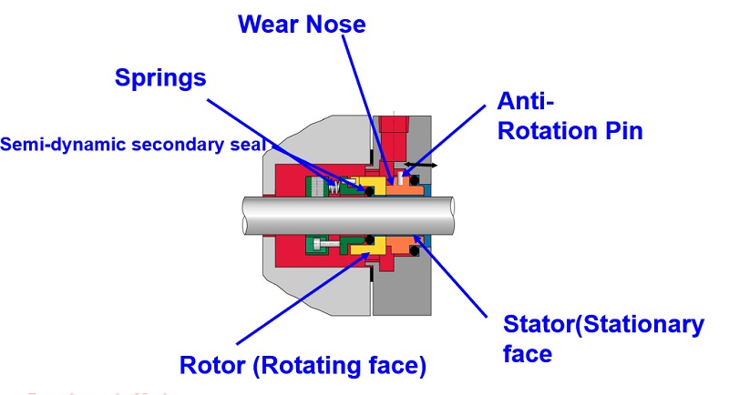
A few basic components and principles in mechanical seal design contribute to a working seal at the interface of the rotating shaft and stationary pump/mixer/seal-chamber housing. Mechanical seals are usually end-face seals or rotating-face seals, but in some designs they can be circumferential or even a hybrid of lip-type seals. In either case, the following components are common to all mechanical seals:
Stationary primary sealing element:fixed to the stationary housing of the pump, mixer or other equipment through which the rotating shaft passes and seals against the rotating primary sealing element
The more common end- or rotating-face mechanical seal designs feature mating faces as the primary sealing elements. Rings of ceramic, carbide, carbon or composites of these materials are lapped flat in the range of less than 1 micron on an axial end face. These lapped faces run against each other, one rotating with the shaft and the other stationary with the equipment housing.
The sealed fluid migrates between the flat faces and forms a stable fluid film at this interface. During shaft rotation, the face materials heat up, wear and degrade quickly without a lubricating fluid film between them. The sealed fluid creates this thin lubricating film.
In a lip-seal-type mechanical seal, a thin film of sealed fluid also lubricates the sealing interface. Rather than two flat rings, the sealing interface is a polymer material deflected against a hard material. This material could be a hardened, coated or plated metal, ceramic, or carbide face or sleeve. One of these elements rotates with the shaft while the other is stationary with the equipment housing.
Leakage is a function of the mathematical cube of the film thickness, so to minimize leakage, the gap at the sealing interface must be kept at a functional minimum. Closing forces are used to optimize this design parameter throughout the operating range of the mechanical seal.
The initial closing force ensures that the seal will function properly from startup. In end- or rotating-face mechanical seal designs, the initial closing force is provided by a spring component, which can be a single coil spring, multiple coil springs, a deflected bellows unit (elastomer or metal), or formed or flat springs. Initial biasing forces also can be created by magnets, compressed elastomers or any other means of applying a closing force between sealing elements. In a lip-type mechanical seal, the initial closing force is typically from the deflected polymer of the lip-type seal or a garter spring for less resilient materials.
The sealing elements must be secured to the rotating shaft and stationary housing of the equipment being sealed. O-rings, gaskets and other elastomer seals stop leakage at these interfaces.
A static secondary seal stops leakage between components that do not move relative to each other. One example is the interface between a sleeve and a shaft, where both rotate but do not move relative to each other. A dynamic secondary seal, on the other hand, stops leakage between components that move relative to each other. An example is a spring-mounted seal face, where the face is free to move as the spring deflection allows, and the secondary seal will stop leakage between the seal face and the component to which it is resiliently mounted.
A lip-type mechanical seal may only require static secondary seals because the deflection of the lip-type seal accommodates equipment operating motion. All effective end- or rotary-face mechanical seals require at least one dynamic secondary seal. This is because the mating faces of the sealing interface are rigid materials that cannot comply with any equipment shaft/housing misalignments, thermal growth and shaft end-play. The dynamic secondary seal will accommodate the relative motion between at least one of the seal faces and the component to which it is mounted.
Mechanical seals are used with many process fluids. Each fluid has different lubrication qualities, but a thin, lubricating film at the sealing interface is always needed. A film that is too thick will increase leakage and may allow particulate between the faces, which will increase wear from abrasion. A film that is too thin will generate heat and cause materials to degrade. Keeping the sealing interface cool and clean will promote longer seal life.
Seal design can influence film thickness by balancing the closing forces on the sealing interface in such a way that the sealing interface does not become overloaded as process pressures increase. A closing force that is too high will lead to a fluid film at the sealing interface that is too thin, generating detrimental heat.
Another way to influence film thickness is to design surface features at the sealing interface that promote hydrodynamic lift between the rotary and stationary sealing elements. This can help create a purposeful separation at the sealing interface that results in a thicker fluid film that provides cooling and decreases face wear.
Primary seal material selection can influence seal life as well. Chemical or process compatibility is just one consideration. Harder materials are more resistant to abrasive processes, but if both sealing elements are hard materials, the wear characteristics may be less desirable in a nonabrasive application.
Using one sealing element made of a softer material and/or one that contains lubricating components such as graphite decreases friction for starting and incidental contact. The use of composite hard faces will also reduce friction by providing microscopic reservoirs of system fluid at the interface.
Thermal conductivity of materials will dissipate heat away from the sealing interface, promoting seal life. Material toughness also can play a dominant role in mechanical seal life. The inherent material surface texture may also play a role in promoting desirable film thickness.
Note that many seal failures result from failed secondary seals that have exceeded chemical compatibility, pressure or temperature limits. Metal parts must be compatible to avoid corrosion, and springs and other hardware must hold up in service.
Process and seal environmental controls greatly contribute to a cool, clean lubricating film at the sealing interface. If the process fluid is a slurry mixture, process pressure will drive the particulate-laden fluid into the sealing interface, resulting in abrasion and accelerated wear.
Environmental controls, such as a restriction bushing and clean flush, can isolate the mechanical seal from the harsh process so the seal is mostly sealing the cleaner, cooler flush fluid. In other cases, the pump product may crystallize, abrading the sealing interface and causing premature wear. Product crystallization can be prevented by using temperature controls, quenching the atmospheric side of the sealing interface, or using a double seal with a buffer or barrier fluid.
There are many process considerations other than abrasion that might prevent a cool, clean lubricating film at the sealing interface. If the sealing fluid has a low vapor point, for example, flashing can result. Flashing occurs when the sealed fluid changes from liquid to gas at the sealing interface, expanding quickly and forcing the sealing elements apart until the pressure and temperature are relieved, only to have the sealing elements collapse back into contact. Mechanical damage to the sealing contact surfaces quickly results in seal failure. No lubricating film is established. Operators must incorporate process controls and ensure proper mechanical seal selection to prevent such upsets. There are many other process conditions that require special attention such as fluids that harden, are toxic, must be kept anaerobic, are part of food or water supply, or present another specific constraint.
Seal environmental controls are often overlooked, resulting in surprisingly short seal life. Many seal failures of this type happen in cool water applications. Cool water is an effective sealing fluid for creating a stable lubricating film at the sealing interface, but failure to apply proper seal environmental controls can lead to seal failure.
Many cool water applications fail prematurely because they are vertical, with the seal installed at a high point in the system where air is trapped. Without properly venting the air out of the seal chamber area, the mechanical seal seals air, not cool water. This is a dry-running condition that generates heat and quickly degrades the materials at the sealing interface.
A common environmental control used in vertical applications is a recirculation line from the seal chamber to pump suction, but in some cases the seals run dry for too long before the fluid replaces the air in the seal chamber.
Poor equipment conditions—caused by bad bearings, cavitation, excessive impeller loads and misaligned shafts—result in excessive motion, vibration and mechanical shock to the mechanical seal. These conditions cause greater stresses, more heat and more opportunity for abrasives to enter the sealing interface.
Mechanical seals are designed to handle a range of motions and conditions, but they are just one machinery component in a larger system. Understanding the basics of mechanical seals and how they may be adapted for different application requirements is critical for choosing the best seal for the job and ensuring optimal system reliability.
We invite your suggestions for article topics as well as questions on sealing issues so we can better respond to the needs of the industry. Please direct your suggestions and questions to sealingsensequestions@fluidsealing.com.

A mechanical seal is simply a method of containing fluid within a vessel (typically pumps, mixers, etc.) where a rotating shaft passes through a stationary housing or occasionally, where the housing rotates around the shaft.
When sealing a centrifugal pump, the challenge is to allow a rotating shaft to enter the ‘wet’ area of the pump, without allowing large volumes of pressurized fluid to escape.
To address this challenge there needs to be a seal between the shaft and the pump housing that can contain the pressure of the process being pumped and withstand the friction caused by the shaft rotating.
Before examining how mechanical seals function it is important to understand other methods of forming this seal. One such method still widely used is Gland Packing.
The stationary part of the seal is fitted to the pump housing with a static seal –this may be sealed with an o-ring or gasket clamped between the stationary part and the pump housing.
The rotary portion of the seal is sealed onto the shaft usually with an O ring. This sealing point can also be regarded as static as this part of the seal rotates with the shaft.
One part of the seal, either to static or rotary portion, is always resiliently mounted and spring loaded to accommodate any small shaft deflections, shaft movement due to bearing tolerances and out-of-perpendicular alignment due to manufacturing tolerances.
The primary seal is essentially a spring loaded vertical bearing - consisting of two extremely flat faces, one fixed, one rotating, running against each other. The seal faces are pushed together using a combination of hydraulic force from the sealed fluid and spring force from the seal design. In this way a seal is formed to prevent process leaking between the rotating (shaft) and stationary areas of the pump.
If the seal faces rotated against each other without some form of lubrication they would wear and quickly fail due to face friction and heat generation. For this reason some form of lubrication is required between the rotary and stationary seal face; this is known as the fluid film
In most mechanical seals the faces are kept lubricated by maintaining a thin film of fluid between the seal faces. This film can either come from the process fluid being pumped or from an external source.
The need for a fluid film between the faces presents a design challenge – allowing sufficient lubricant to flow between the seal faces without the seal leaking an unacceptable amount of process fluid, or allowing contaminants in between the faces that could damage the seal itself.
This is achieved by maintaining a precise gap between the faces that is large enough to allow in a small amounts of clean lubricating liquid but small enough to prevent contaminants from entering the gap between the seal faces.
The gap between the faces on a typical seal is as little as 1 micron – 75 times narrower than a human hair. Because the gap is so tiny, particles that would otherwise damage the seal faces are unable to enter, and the amount of liquid that leaks through this space is so small that it appears as vapor – around ½ a teaspoon a day on a typical application.
This micro-gap is maintained using springs and hydraulic force to push the seal faces together, while the pressure of the liquid between the faces (the fluid film) acts to push them apart.
Without the pressure pushing them apart the two seal faces would be in full contact, this is known as dry running and would lead to rapid seal failure.
Without the process pressure (and the force of the springs) pushing the faces together the seal faces would separate too far, and allow fluid to leak out.
Mechanical seal engineering focuses on increasing the longevity of the primary seal faces by ensuring a high quality of lubricating fluid, and by selecting appropriate seal face materials for the process being pumped.
When we talk about leakage we are referring to visible leakage of the seal. This is because as detailed above, a very thin fluid film holds the two seal faces apart from each other. By maintaining a micro-gap a leak path is created making it impossible for a mechanical seal to be totally leak free. What we can say, however, is that unlike gland packing, the amount of leakage on a mechanical seal should be so low as to be visually undetectable.
From the operational point of view of centrifugal pumps, it becomes essential to correctly align the pump and the drive to ensure the mechanical seal functions properly. Attention shall be given to is nozzle loads. During the design as well as during the actual installation, the consideration of the nozzle loads is important. Higher nozzle loads beyond allowable values could lead to deformed casings and may be detrimental to mechanical seals due to rubbing of the shaft at the clearances. The sizing of the shaft in case of end suction pumps (and also the overhang) has to be controlled, which could result in excessive deflection at the mechanical seal faces.
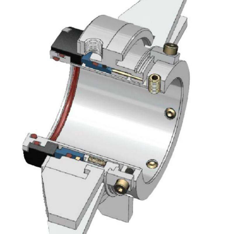
When it comes to reliability of sealing the process liquid, a dual seal arrangement is the preferred choice. There are three arrangements defined in API 682: arrangement 1, 2, and 3. The arrangement 1 is the single seal arrangement. The arrangement 2 is the dual seal arrangement with unpressurized buffer liquid at the outboard seal. Finally, arrangement 3 is the dual seal arrangement with the pressurized barrier liquid at the outboard seals. With the barrier liquid being pressurized in arrangement 3, there is no leakage of process liquid to the atmosphere, and hence it is the most reliable option when it comes to applicability of stringent environmental norms from the point of view of the end user.
However, in order to ensure proper functioning and reliability of dual seals, the operational environment of the pump, piping, seal support system, and monitoring systems play a vital role. There are typically four API piping plans for seal support systems: API Plan 53 A, B, and C, and Plan 54.
All three variations of Plan 53 are similar from the point of view that they circulate the barrier fluid using the pumping screw inside the mechanical seal, but the methods of pressurizing the barrier fluids are different. Plan 53A uses direct pressurized nitrogen to pressurize ¬fluid in the reservoir. This plan is popularly used in most of the cases due to less complexity and also availability of nitrogen pressurizing source at site. However, to ensure reliability, one has to be careful about the absorption of nitrogen gas into the barrier ¬fluid. The amount of gas being absorbed is proportional to the pressure of the barrier system. The barrier ¬fluid with absorbed gas then reaches the seal faces due to circulation and at the ¬fluid film, due to depressurization, the gas may come out and hamper the seal performance. This is a reliability concern, and hence most of the seals with Plan 53A are limited to 10 bar (gauge) pressure. Plan 53B uses a bladder accumulator as a means of pressurization of barrier fluid. This overcomes the limitation of Plan 53A and the absorption of nitrogen into the barrier liquid, which limits the system pressure, which can be used in high pressure applications. The advantage of the Plan 53B is that it can be used in remote locations where the external source of pressurization is not available. The pressure of barrier liquid is maintained due to the expansion of the bladder inside the accumulator, which also enables the supply of make-up barrier liquid to compensate for a small amount of leakage of barrier -fluid. However, the monitoring of the liquid level in the reservoir is not possible, and as such, the sizing of accumulator considering the seal leakage and maintenance interval is critical. As the bladder expands to compensate for seal leakage, it needs to be refilled with barrier liquid. The usual cycle of refill is 25 to 28 days. Considering this as a basis, the size of the accumulator and the pre-charge pressure of nitrogen is estimated.
Plan 53C uses a piston as a means of pressurization of barrier ¬fluid inside the accumulator. The advantage of this design is that it uses the process fluid pressure from the seal chamber directly on the bottom side of the piston, whereas top side is exposed to the barrier liquid. The pressurization is achieved by the difference in the areas. The area exposed to process liquid is larger and is designed with ratios ranging from 1:1.1 to 1:1.25. As the seal chamber pressure is being used as a reference, the system itself takes care of process pressure fluctuations. However, as the piston is in direct contact with the process fluid, the material selection becomes essential. Also, the properties and quality of process ¬ fluid shall be carefully evaluated, it should not hinder the movement of the piston within the accumulator. Another important factor is the dynamic sealing of the process fluid from the barrier fluid. The failure of the piston seal will result in the equilibrium of pressures on both sides of piston, and because of the piston movement, friction and drag come into play. Thus, the plan is not so reliable for low pressure applications and recommended to be used in the applications with pressures greater than 7 bar (gauge).
Although a mechanical seal is a critical piece of equipment, it shall not be treated in isolation and due consideration should be given to the operating environment of the pump, seal support system, and most importantly, the perfect selection for the given application.
Abhijeet Keer is a design engineer who has been working in the fi eld with centrifugal pumps for over seven years. With strengths in mechanical construction and materials, he has gained valuable knowledge working in design with major players in pump industry, such as KSB Limited and Kirloskar Brothers Limited. He completed his Bachelor’s Degree in Mechanical Engineering from University of Mumbai, India. His professional experience covers new product design and developments, material selection and application engineering, and complete mechanical constructions.

Approximately 88% of industrial process centrifugal pumps in the USA use mechanical seals which have been in commercial use since the 1920s. The concept of sealless magnetic drive centrifugal pumps has been around since the 1940s. In the past 30 years increased market demand for sealless pumps have driven pump manufacturers to continue to develop and evolve sealless pump designs. There are two primary types of sealless pumps; magnetic drive and canned motor pumps. This article will focus on magnetic drive pumps.
What key points should you consider in deciding whether your application is best suited for a pump with a mechanical seal or a magnetic drive sealless pump?
Initial cost is a consideration although not necessarily the most important one in critical services. However in most cases it is very important to go beyond the initial cost. Single mechanical seal pumps typically have lower initial cost BUT a much higher cost over the life of the pump. A properly selected and operated mag-drive pump offers years of trouble-free service; some users have run magnetic drive pumps for decades with no maintenance whatsoever except for routine oil changes or motor bearing grease requirements. For this reason many pump users are slowly retiring all their mechanical seal pumps and replacing them with magnetic drive pumps.
To increase the reliability of a mechanical seal pump double mechanical seals can be used, however they are expensive and generally require an expensive and elaborate barrier fluid system which are a challenge to operate and maintain. Typically a double mechanical seal pump with a seal pot and auxiliary equipment will have a higher initial cost than a sealless magnetic drive pump which makes the choice of which type of pump to buy a no brainer.
Furthermore, a close-coupled configuration can be readily used on mag-drive pumps up to 40 hp, depending on the manufacturer. The close coupled configuration not only eliminates the coupling cost, but the need for motor/pump shaft alignment, which if not done correctly, can result in mechanical seal failures as well as ball bearing failures of the pump power frame and/or electric motor, both of which result in costly downtime. Additionally a close coupled pump package has a much smaller foot print than a long coupled pump, making mag-drive close coupled pumps ideal for applications where space is limited.
Mechanical seals are the weak point in a mechanical seal centrifugal pump whereas the internal ceramic inner magnet bearing system is the weak point for magnetic drive process pumps.
The process fluid is circulated within the magnetic drive pump to cool and lubricate the pump’s internal bearing system, just as the mechanical seal in a standard centrifugal pump is cooled and lubricated by the pumped fluid or an external flush. However, unlike a pump with a mechanical seal that allows the pumped fluid to escape the pump when it fails, the mag-drive pump’s bearings and the shaft that supports them are located within a hermetically sealed rear casing/containment shell, so that potential fluid leakage into the atmosphere in the event of a catastrophic failure is virtually eliminated.
Running any centrifugal pump dry will result in a failure. However, the failure mode is different for a pump with mechanical seals versus a magnetic drive pump. Mechanical seals require a small amount of liquid to pass across their faces to provide cooling and lubrication otherwise the seal will run dry and fail. A small amount of that liquid will escape the confines of the seal faces and leak into the atmosphere as either a liquid or vapor. This is why mechanical seal pumps must be monitored for fugitive emissions in VOC (volatile organic compounds) as well as toxic or noxious applications.
Magnetic drive pumps require internal circulation of the pumped liquid to cool and lubricate the ceramic bearing system that supports the inner magnet carrier. To prevent magnetic drive pump bearing systems from running dry many manufacturers recommend a simple power monitoring device that shuts the pump down in the event of upset conditions such as low flow or no flow on the suction or discharge side of the pump. Some mag drive pump manufacturers have developed bearing materials/coatings that are more forgiving of upset conditions and can run dry for limited periods of time depending on the size and weight of the inner magnet assembly. Several companies are working on alternate bearing technologies which will eventually allow dry running for extended periods of time. The typical magnetic drive pump bearing system is manufactured from silicon carbide which while extremely hard is susceptible to thermal shock if the pump is run dry for a period of time followed by a slug of cold fluid entering the pump suction. In addition, different thermal expansion rates between pump components can cause mechanical damage and failures during run-dry conditions, commonly seen on start-up with no liquid in the pump. Another concern is that dry running can increase the temperature to the point that it will deteriorate the strength of the rare earth magnets.
A major advantage of some magnetic drive pump designs is reduced radial loading compared with standard, seal-type, overhung models. For example, as illustrated below, a straddle-mounted design with bearings on either side of the inner magnet assembly provides excellent stability, reduces radial loading and allows the pump to operate smoothly when run too far to the left or right of BEP. This is even more critical with high specific gravity liquids such as sulfuric acid.
The straddle mounted inner magnet bearing design illustrated above commonly offers many years of operation without maintenance except for routine oil changes or motor bearing grease requirements. Few if any mechanical sealed pumps in process applications will operate this well.
Magnet drive pumps are an excellent, cost-effective option for providing years of trouble-free operation in many industrial process applications, potentially saving pump users tens of thousands of dollars in maintenance and repair costs over the lifetime of the equipment. Magnet drive pumps are definitely not the answer to every pump application however, they can be an ideal solution across a broad range of applications where eliminating mechanical seals is desired for cost reduction or safety concerns. Magnetic drive pumps are excellent for applications involving toxic, explosive, corrosive, noxious, high purity or expensive fluids. In one particular hot oil application that the author is familiar with, over $100,000 of heat transfer fluid was being wasted each year just to cool and lubricate a number of mechanical seal pumps because liquid was lost across the seal faces in normal operation and from additional leakage when seals were damaged or broken. Less “dangerous” fluids can also be added to the list, including liquids that, when leaked onto a plant floor, might cause employees to slip and injure themselves. Similarly, using magnetic drive pumps to move process fluids with an objectionable odor can provide a much more pleasant working environment.

But here I want to emphasize the importance of pumps, mechanical seals, and seal support systems. Without pumps, there is no process. Without the proper seal support systems, high temperatures in seal chambers may damage mechanical seals and lead to pump leakage.
Several factors contribute to high temperatures in the seal chamber, which in turn leads to mechanical seal degradation. A mechanical seal and seal support system may have been perfectly matched to the initial process, working reliably for years. However, a change to a higher-temperature process can exceed the capability of the mechanical seal and capacity of the seal support system.
At higher temperatures, elastomeric components in the mechanical seal may begin to deteriorate. For example, beyond 300° Fahrenheit (150° C) ethylene propylene components eventually degrade and leak. Some hydrocarbons coke at higher temperatures and impede the free movement of mechanical seal components. And process fluids at high temperatures are prone to vaporize, or flash, across the seal faces, causing fugitive emissions.
With increased temperatures of process fluids, the seal support system may no longer be able to maintain the barrier or buffer fluid temperature or flow rate required to maintain the integrity of a dual seal arrangement. When mechanical seals and seal support systems can no longer ensure pump reliability it’s time to select seals, support systems, and components better suited for the job.
If a change to a higher process temperature is causing unanticipated leakage, consult with your preferred mechanical seal vendor. The materials alone can present an overwhelming number of options as seal technology and design continue to evolve. There are now more choices than ever, including:
⇒ Seal faces—carbon, stainless, ceramic, tungsten, and variants incorporating silicon, graphite, or nickel—engineered for resilience and compatibility with process fluids
The benefit of these choices is the ability to match mechanical seals to the specific needs of the process, maximizing seal performance and reliability.
The mechanical seal requirements of high-temperature hydrocarbon processes are best met with dual/ between seal arrangements. A dual seal support system provides fluid between two seals, buffer fluid at a lower pressure than the process fluid, and barrier fluid at a higher pressure than process fluid.
In contrast to a single mechanical seal arrangement where seal degradation or failure results in fugitive emissions or outright leakage, the two seal arrangement provides a more reliable means of preventing high-temperature hydrocarbons from leaking. Here too, rotating equipment and reliability engineers have a number of dual seal design options to choose from, including:
Face-to-face configurations are used in space-constrained areas that cannot accommodate back-to-back or tandem arrangements. Seals share a common stationary component which, if compromised, leads to leakage. You can select from buffer or barrier fluid options.
Gradual or sudden changes in barrier or buffer fluid pressure provide evidence of problems with seals. An experienced mechanical seal vendor can help you navigate the options available to ensure mechanical seals and their components meet each of your specific needs.
Equally important to the reliable functioning of mechanical seals in high-temperature processes is the selection of seal support systems. The mechanical seal you choose will guide the seal support system plan that best meets your needs.
Seal support systems for dual seals are divided into two categories: buffer and barrier. While that seems to simplify the selection, there are a variety of options for each category. To give you an idea of what’s available, I’ve listed a few of the mechanical seal support system options below.
Circulates pressurized barrier fluid from a reservoir to the dual seals. Use plant nitrogen, bladder accumulator, or piston accumulator to supply seal pot pressure. Any leakage across the process side seal is barrier fluid that lubricates seal faces and migrates into process fluid.
Provides clean, dry pressurized barrier gas (typically nitrogen) to the dual seals from an external source. Any leakage past the atmospheric seal is pure nitrogen.
For each of these plans, there are options to fine-tune the seal support system and provide a greater level of reliability for mechanical seals operating in high-temperature environments. Among the many options you may want to include:
An experienced seal support vendor can save you time and money, helping you select and configure the seal support systems with the right components for each of your high-temperature hydrocarbon pumping needs.
Swagelok has been meeting the mechanical seal support system needs of Northern California refineries for more than 50 years. When you work with Swagelok, you have the benefit of a local vendor with facilities in Concord, Fremont, and Santa Clara. Being local translates into on-site support, field verification of your requirements, and rapid delivery of seal support system assemblies, components, and parts.
To find out more about howSwagelok Northern California can help you address the challenges of maintaining the proper environment for mechanical seals in high-temperature serviceContact our team today by calling 510-933-6200.
Paul holds a B.S. in Mechanical Engineering from North Dakota State University. Before joining Swagelok Northern California, he was the West Coast Regional Sales Manager for an organization involved in pneumatic and hydraulic applications where he supervised product distribution throughout the western United States, Canada, and Mexico. While in this role, he was able to help provide technical and application-specific expertise to customers and distribution to drive specifications.


 8613371530291