
mechanical seal failure analysis factory
When a mechanical seal fails in one of your operation’s vital pieces of equipment, figuring out the cause of the failure is often even more important than procuring a replacement seal. After all, if there is an underlying issue causing your seals to fail, replacing the seal is only going to be a temporary fix. Unless you plan on purchasing and installing new seals on a regular basis – something that can quickly become both expensive and time-consuming – figuring out the cause of your seal failures is an essential objective.
This is where mechanical seal failure diagnostic services can prove highly valuable. By simply examining your broken seal, we at Gaddis Mechanical Seals are able to pinpoint the exact cause of its failure, enabling you to perform whatever repairs are necessary to keep the same issue from happening again in the future.
At Gaddis Mechanical Seals, we strive to make our seal failure diagnostic services as convenient as possible for our valued customers. All you have to do is send us your broken seal along with any available information regarding where the seal was located and the events leading up to its failure. From there, our expert team will perform a wide range of diagnostics to determine the exact cause behind the seal’s failure.
This includes inspecting the seal’s O-rings, face, springs, gasket, and every other component. By determining the exact component within the seal that failed and analyzing the design of the equipment that it came from, we are able to provide our customers with an accurate and detailed description of exactly what needs to be fixed in order to prevent the same issue from happening again.

Fluid Sealing International offers Mechanical Seal Analysis (MSA) service. As a seal is disassembled all parts are inspected to determine their condition with respect to original specifications. It is during the MSA procedure that a failure mode can be identified and recommendations can be determined. These may include changes required in equipment operation, suggested environmental controls for improved performance, upgrades in seal materials, or even a change in seal design.
After a complete inspection of the seal, all major parts are cleaned and replaced. Where necessary, Fluid Sealing International can provide Mechanical Seal Repair Services to repair your seal.

Mechanical seals prevent pumps from leaking by containing the pressure of the pumping process and withstanding the friction caused by the rotating shaft. The right seals provide reliable operation, less wasted product, more cost savings, and fewer housekeeping issues. However, why do mechanical seals fail?
In many pump systems, a mechanical seal is the first component to fail. They are also the most common cause of pump downtime and account for more pump repair costs than any other part of a pump. Often, however, the seal is not to blame. Other culprits include:Bearing wear
Therefore, teams must install and maintain seals properly to prevent failures. Teams must pinpoint the root causes of each failure. But how do plant and maintenance managers isolate the root cause though?
One option is to have a seal manufacturer perform a seal failure analysis. Some seal manufacturers offer complimentary seal analysis on any seal, not just theirs.
End users simply send their mechanical seal to the manufacturer’s engineering team. If multiple seals need to be analyzed, they may come on-site to perform the root cause analysis. Most reviews canbe completedin about two weeks.
With a seal failure analysis, experts deliver a complete diagnosis of why the mechanical seal failed and what actions to take to prevent future failures. The experts who examine the seal can ensure that the ideal seal for the application has been selected. If not, they recommend alternate technologies.
After an analysis, the manufacturing ream will also help end users optimize their system conditions and achieve the best possible operation from their assets. Optimizing mechanical seal performance also improves shutdown to shutdown processes. This information, along with alternative proposals as needed, help end users prevent further failures and improve their return on investment.
Many problems with a system may be discovered by investigating a failed mechanical seal. In most instances, a seal problem is not the reason for the failure. Something else happened to cause it.
The story of what the seal experienced during operation, before it failed, can be revealed by investigating the failure. An analysis may determine or confirm:If misalignment or other mechanical problems exist in the pump system
Eliminating the problems identified by the seal failure analysis may have a huge impact on the system. Several improvements may be realized, including:Optimized operating conditions
For instance, a stationary seal face is cracked, originating from the drive pin slot. Also, sticky residue has adhered to the face. This crack means something different than a stationary seal face with a crack located at a different position and product residue that is fairly clean and not tacky.
Both cases look the same on a simple table listing all the seal damage. However, the failure cause is different. In the first example, the crack was caused by the product attempting to stick the rotary and stationary faces together. This adhesion caused increased torque on the stationary pin. This caused the stationary face to crack.
In the second example, the crack was likely caused by impact. This indicated that the seal was not installed properly. Different symptom combinations reveal multiple failure modes.
In conclusion, to determine the true reason that a seal failed, seal failure analysis is required. Without a diagnosis of the system problem, failure will continue.
Jack Ferguson is a seal reliability engineer with Sealing Equipment Products Co. Inc. (SEPCO). He is a recent graduate of Clemson University with a degree in mechanical engineering. Ferguson may be reached at jackf@sepco.com.

Mechanical seal failures are the most common cause of pump downtime and failure, so mechanical seals and seal support systems must be very carefully designed with components and options selected according to the specific application. However, even high-quality seal support systems can fail unexpectedly for a variety of reasons. When this happens, it’s critical to conduct mechanical seal support failure analysis quickly and accurately, because every minute of downtime results in lost production.
Identifying the failure mode and root cause of a mechanical seal failure allows you to not only correct the immediate problem but prevent it from happening in the future. Thorough mechanical seal support failure analysis can help you understand the conditions under which the seal failed.
In this article, we’ll look at the three most common types of seal support failures—leaks, overheating, and seal failure—what can cause them, and how to prevent them with proactive measures.
Mechanical seals minimize leakage around rotating equipment by creating a “seal” between two very flat surfaces—one stationary and one rotating. These mechanical seal faces inevitably produce some leakage, but the leakage normally evaporates immediately and isn’t a problem. When leaks become noticeable, it’s time to perform mechanical seal support failure analysis to find out why.
When troubleshooting mechanical seal leaks, make note of any unusual noises, damage, or other symptoms accompanying the leak. Use the table below as a starting point to help you identify the cause of the leak.
Overheating indicates either friction between rotating components or excessive fluid temperatures. There are two main reasons mechanical seals overheat: inadequate cooling and excessive friction. Refer to the table below to help diagnose the problem.
As you can see, there is a lot of overlap between the causes of leaks and overheating. Many mechanical seal failure modes can be traced back to the same underlying causes, so be sure to check for leaks as well and use the leak troubleshooting table to investigate.
Excessive heat can eventually lead to heat checking. Mechanical seal heat checking can be identified by fine radial cracks in the seal face caused by excessive stress from the mechanical load and thermal expansion. These cracks may be barely visible to the naked eye, so heat checking can go unnoticed until failure occurs and it’s too late to save the seal. The risk of heat checking increases with high temperatures and high-viscosity fluids like those used in SAGD. It is more common in brittle materials like tungsten carbide.
The same underlying issues that cause leaks and overheating can eventually lead to complete seal failure. A mechanical seal failure likely began as a leak or overheated condition that went unaddressed. The same troubleshooting procedures for leaks and overheating apply, but once the seal has failed, correcting the problem becomes much more difficult. Therefore, it’s important to be proactive and check for problems like leaks and overheating before they cause major problems.
Do you still need help with mechanical seal support failure analysis, or want to learn more about how to be proactive in preventing failures? Field Advisors at Edmonton Valve & Fitting can perform an onsite or remote evaluation to determine the cause of failure and make recommendations on upgrades, component materials, tubing diameters, and instrumentation to help deter mechanical seal failures.
To find out more about how Edmonton Valve & Fitting can help with mechanical seal support failure analysis, contact usthrough our websiteor by calling 780-437-0640.

Miscellaneous. Sometimes a seal is observed to be leaking, but when removed and examined there is no obvious damage. This often happens when sealing light hydrocarbons. For these products, the liquid may flash to a vapor between the seal faces. Since most seals are designed for liquids, the resulting force imbalance causes the faces to “pop open”. The solution may involve changing the balance ratio, seal type or installing an external flush.
Sometimes seal failures are so strongly related to the pump and its performance that reliability can be improved only by modifying the pump. The pump may have a true design problem or may simply have been misapplied. Some of the more common pump related seal failures are:
Low flow. In spite of the performance curve, which shows operation from no flow to maximum, centrifugal pumps may not operate smoothly at less than about 50% of Best Efficiency Point (BEP) flow. Vibration and noise may increase markedly at less than this minimum stable flow. The result is a decrease in seal life. Resolution of this problem many require hydraulic modification by the pump manufacturer or a by-pass line to artifically increase flowrate.
Excessive shaft deflection. If the shaft deflects, the seal must move axially each revolution to compensate. API Standard 610 for centrifugal pumps specifies a maximum of 0.002″ shaft deflection at the location of the seal faces. Some older pumps and non-API pumps may not meet this specification. In particular, older pumps designed for packing may have excessive shaft deflection. Shaft deflection is reduced by increasing the shaft diameter and/or reducing the bearing span or shaft overhang.
Cavitation. Cavitation has been rightly and wrongly blamed for many ills in both pumps and seals. Certainly cavitation increases pump vibration and vibration reduces seal life. Studies have shown that the simple 3% head loss rule which is used to define NPSHR may not adequately define the onset of cavitation problems. Also, operation at low flow sometimes produces symptoms similar to cavitation.
by Umeet BhachuWeibull analysis is an important statistical tool in the realm of reliability engineering. It helps in the modeling of increasing, decreasing and constant failure rates.
In maintenance organizations where time and cost of repair are crucial elements, it is of paramount importance for a reliability engineer to determine swiftly and accurately the failure modes and root causes underlying a particular issue to avoid further machinery breakdowns. This translates into cost savings because a pro-active approach, rather than a reactive maintenance attitude, forms a basis for implementing advanced programs, such as reliability centered maintenance (RCM), in the operating organization.
It is prudent, however, to assess the data (in our case time between failure) for randomness and distribution prior to performing such an analysis. Data following a renewal process is independent and identically distributed (iid), which means the data arises from a single population. If the failure data does not follow a renewal process, the Weibull analysis leads to incorrect predictions about the nature of machine reliability. This often causes inappropriate action on the part of maintenance, resulting in costly and unwarranted repairs. Improving or degrading trends in reliability leads to failure data that does not follow a renewal process. There are various methods, both graphical and analytical, to assess this data before inputting it for a Weibull analysis. We will use one such method called the Laplace trend test.
Consider the case of an API 610-compliant centrifugal pump, one of the most common and critical pieces of rotating machinery in a refinery. Mechanical seal failures are often the initial reason such pumps are brought down for maintenance or repair. Usually, this is not because of an incorrect seal design selection or a faulty seal, but simply because of the way the mechanical seal is operated. Mechanical seals are one of the weakest links in pumps and turbomachines. They fail due to vibration, misalignment, changes in process conditions, incorrect settings on the seal flush plans and various other reasons. Weibull analysis, when properly used in this context, helps the reliability engineer determine and qualify the failure mode without having to stop the machine or wait for the next failure to happen. By using the past failure and maintenance history of the machine logged in the plant’s computerized maintenance management system (CMMS) to calculate Weibull parameters, such as the shape parameter Beta (ß), Weibull can help in determining why the failure occurs.
As a related case, consider a charge pump in a hydrocarbon service, pumping volatile gas oil as the finished product. The pump has a pressurized dual mechanical seal with an API Plan 02/53B. The normal pumping temperature is 85 degrees C, with a maximum temperature of 120 degrees C. The seal experienced multiple failures in the past that have subsequently caused the unit to shut down for seal replacement on both the inboard and outboard ends of this critical pump. Thorough scans of the CMMS system revealed various work order (W/O) and seal failure histories that helped in determining the time to failure (TTF) during each event. TTF provides the input for analysis that will then help to understand and draw meaningful conclusions on why the seal is failing.
We first use the Laplace trend test to determine if the data is suitable for Weibull analysis. Detailed information on computing and using Laplace testing can be found in the various references provided at the end of this article.
When the score is greater than +1.96 or less then -1.96, we are 95 percent confident that there is a statistically significant upward or downward trend. This disqualifies the data from being iid and coming from Weibull analysis is an important statistical tool in the realm of reliability engineering. It helps in the modeling of increasing, decreasing and constant failure rates. Reliability Engineering for Maintenance reliability engineering Re Analysis of a dec/jan14 a single population, leading to a non-qualification from further analysis using Weibull.
However, in our case, the Laplace score is closer to 0, showing that no discernible upward or downward trend exists and the data is essentially random failures qualifying it for the Weibull analysis. So let us now proceed to performing a Weibull analysis on our failure data.
Weibull distribution can be created for any data and is flexible in modeling a wide range of data. In our example, we use only failure data to model this distribution without incorporating non-failure (also called censored or suspended) data. While the inclusion of suspended data provides a more accurate distribution, we chose to ignore it due to the quality and accuracy of the data from the CMMS. Table 1 shows the filtered data and the time to failure for each of the failure events. The red line item shows seal upgrade from a different seal vendor performed during April 2011.
In reliability engineering, the bathtub curve is used to represent failure rates with passing time. The shape parameter, also called Beta (ß), helps us in understanding if the failure rate is increasing (wear out conditions) where ß>1, constant (random failures) where ß=1, or decreasing (infant mortality) where ß<1.
In Figure 1, prior to the upgrade, and Figure 2, after the upgrade, it is seen that ß is less than 1, pointing to the fact that these seals are failing in the infant mortality zone. It should be noted that we have a small sample size (failures) for both situations. However, it has been observed by Dr. Robert B. Abernethy, a leading expert in Weibull statistics, that the Weibull method works well for performing engineering analysis, even with such small sample sizes.
It is interesting to note that despite the upgrade on the mechanical seal, the failure pattern was not significantly altered. The seal was unable to clear the infant mortality zone successfully. One of the reasons leading to infant mortality in mechanical seals is connected to the incorrect design and application of the seal. When a mechanical seal is incorrectly designed or selected for a given application, there seems to be an increase in the number of failure incidents during the early life of the seal. The Weibull plot helps draw our attention to the fact that careful consideration needs to be implemented when selecting the right seal design for the application.
From Table 2, the reliability of the seal actually dropped further after performing the seal upgrade by the new vendor. This reflects the fact that the upgrade did not have the desired effect on improving seal reliability in this particular application.
Based on the root cause analysis performed on these mechanical seals (both prior and after the upgrade), we have seen them running at higher temperatures and causing face distortion and other issues leading to early failures. The higher running temperatures were attributed to cooling limitations during operation, resulting from the inability of the selected seal flush plan to cool the seal sufficiently in conjunction with the seal design. The initial seal design selected for the pump prior to upgrade was not an effective design, particularly in regards to the seal face orientation for this application. Weibull modeling is a good tool in predicting reliability and determining gross failure modes for many simple and complex engineering and maintenance related equipment breakdowns. The distribution finds prominent use in implementing maintenance strategies in many world-class organizations by quantifying failures. When failures are random (ß=1), a good condition monitoring program coupled with effective preventive maintenance practices help prolong equipment life. When failures are in the infant mortality zone (ß<1), as we have seen with the mechanical seals, then careful attention needs to be given to the design, fabrication, operating procedures etc. And finally, when failures belong to the wear out zone (ß>1), then a decision has to be made to either run the equipment to failure or develop a proper program for maintenance and overhaul of such equipment, which would include availability of spares as required. It is noteworthy that Weibull modeling information also acts as a valuable asset in project engineering by giving the project team important information during design and selection of machinery based on past equipment performance.
This article demonstrates the importance of using a pre-qualification test, such as Laplace, prior to performing a Weibull analysis. Negligence in performing a pre-qualification of the data can lead to incorrect analysis, subsequently causing costly and unwarranted repairs. Plenty of papers dealing with Weibull do not stress the importance of pre-qualification testing of the data before performing analysis. Detailed root cause analysis should have been the key focus after the initial failures on the first seal. However, in the absence of this approach, the second seal upgrade was also found ineffective due to potential incorrect seal/elastomer design and selection, consequently resulting in repeated failures in a short span. The second upgraded seal failed again in the infant mortality zone due to the similar reasons that caused the first seal to fail. The Weibull method is not the be-all and end-all solution to maintenance reliability problems. However, it is but one tool, and an important tool, in complementing other analysis and empirical methods used to troubleshoot and proactively ensure a higher uptime for the plant.
SEAL FAILURE ANALYSIS RESULTS The overwhelming reason for a pump to enter the shop is because of failure of the mechanical seal or packing, yet very few companies are regularly troubleshooting these seals. Ten to fifteen minutes spent at this critical juncture can mean doubling or tripling the life of the seal going into service now.
It is not difficult to determine the cause of failure in 80% of the applications common in industry today. Any company buying mechanical seals from a reliable vendor has the right to expect a sensible failure analysis on the majority of their seal failures. The seal rep is seldom at the shop when the pump comes in for repair, but the folks changing the seals can do a very good job of identifying the reason for failure: steps taken at this point can substantially improve the reliability of the application and save the Corporation far more money than the cost of this time invested. Failure to address the problems evident almost certainly dooms the pump to a short service life upon rebuild.
For the purpose of this report, I will not discuss packing failures but will focus on the major causes of seal failure. The following data is compiled from the records kept at two chemical plants on seals I have personally inspected. The totals expressed represent totals for the plant over a two year history and are not application specific. In most cases, the seals were reviewed after the pump was already back in service, but using the form included in this report has allowed these clients to increase the life of the seals used and has increased the Mean Time Between Failure (MTBF) dramatically over the past two years. CLIENT ONE: a large plant with relatively simple processes and over 600 pumps. This plant has a large powerhouse which it can use for co-generation purposes as well as to supply steam needed for processes in-house.
This client uses a wide variety of seal designs and materials of construction. These designs are component seals, split seals, cartridge seals (single and double/tandem). CLIENT TWO: a medium sized plant that two years ago standardized on cartridge seal designs. This plant does not have a large powerhouse, but runs significantly more involved pump/seal applications (evaporation/condensing/reaction loops/etc.) which lead to other concerns.
RESULTS There is a great deal that can be gleaned from these two plants experience. The largest contributing failure in each case was I.D./O.D. rubbing of the rotary seal member against some object, most commonly the bore of the stuffing box. There have been numerous studies completed and documented that clearly prove the value of large bore stuffing box/seal chambers for mechanical seals. The two plants listed have instituted on-going upgrades for their pump populations; if a seal comes out and shows rubbing as the cause of failure, they immediately return to the previous work order on this particular pump. If that failure report also states rubbing as cause of failure, the stuffing box is replaced with a seal chamber on the spot, prior to seal replacement. The concept of “Shaft Deflection Ratio” has been discussed at length in previous issues of this magazine and countless others devoted to our industries. The stiffer the shaft ratio, the better the pump is able to perform off its Best Efficiency Point (BEP).
A good rule of thumb is that a ratio value less than 60 will guarantee seal life is increased dramatically in “Off BEP” operating conditions. Remember that your pump operates where its pump curve crosses the system curve: systems age and change over time ( a gate valve is replaced with a globe valve, long horizontal runs of piping build up solids, etc.). Pumps purchased for design conditions that don’t match those given the pump vendor EXACTLY can become headaches for maintenance and operations from Day One. The second greatest cause of seal failures was related to o-ring failure. The proper o-ring for an application must address both the fluid being dealt with AND any fluid used to clean the system. VITON might be the proper material for the normal application: what if your system is cleaned every shut down with a caustic steam solution?
You lose the seal a week later and the failure analysis states o-ring failure; is the connection made between the caustic steam washout and the failure of VITON? You are far better off stipulating more expensive o-rings which can survive both conditions than losing seals after your turn-around, when the plant and system are up and have to run. Please also note the drop in seal failures due to poor installation when comparing Plant One and Plant Two. With the decrease in maintenance budgets and personnel, the increasing utilization of “multi-craft” people demands simpler seal designs for installation by off-shift personnel. Component seals can be very difficult to install and are sensitive to dimensional information often unknown and/or unavailable to “back-shift” employees. “The road to Hell is paved with good intentions”; if your plant has downsized in the maintenance department ( and whose plant hasn’t?) cartridge designs may justify their additional cost because of their ease of installation. Don’t blame an electrician for shortened seal life when complicated seals are being installed!
Note also the frequency that bearing problems cause seal problems; the two are inextricably intertwined. Lip seals were designed around the time of the Second World War; they were designed for automotive water pumps. They have a limited design life which is far short of bearing design life. Bearings are seldom a failure because of fatigue; far more commonly, they fail from contamination and water emulsions in a pump’s bearing housing.
Upgrade your lip seals every time you change bearings on your pumps and you will see the bearing life triple and quadruple. Upgrade from lip seals to whatever your engineering staff decides is best; labyrinth seals, full face seals, magnetic seals, etc. Which one of us would buy equipment designed in the Forties today for any application in our plants or homes?
Finally, TRAIN YOUR OPERATORS!! They deserve and need training, because they are the people causing the majority of your seal and bearing failures. I have yet to work with a maintenance man who didn’t care about the quality of his work; maintenance people are not the ones wrecking the production equipment. Untrained operators regularly run pumps dry, start them with closed suction or discharge valves, and fail to report increased noise or vibrations from the equipment they run. They don’t do this to sabotage the plant; they do it from ignorance. Production “owns” the equipment: maintenance just “borrows it” when it needs to be repaired.
Stop cursing your maintenance budget and start training your operators: you’ll see how quickly maintenance can become a profit center for your plant instead of “the ugly step-child” it too often is perceived as in the plant budget and planning sessions. CONCLUSIONS Seal failure analysis does not have to be complicated or time consuming. Most of it can be done by your in-house staff in less than ten minutes at the time of failure with reasonable accuracy. Don’t lose the data; gather it on the simple form enclosed, and log it into a simple data retrieval system. Marshall the assets you already have in-house to get a better view of your problem pump applications, make a few simple upgrades on repeat offender pumps, and improve your bottom line today. Plants can readily improve their overall profitability with better training of operators and giving their maintenance people the freedom to make some simple upgrades at the time of seal/bearing failures.

All pump seals leak. Mechanical seal leakage involves fluid becoming trapped between the rotary and stationary surfaces and vaporizing. The resulting vapor barrier—also referred to as fluid film—is what lubricates the seal surfaces. In a healthy seal, this leakage isn’t noticeable (occurring at a rate of only about 0.030 drops per minute). Typical leakage paths are: between the faces; sleeve and shaft; rotary-face seal surfaces; stationary-face seal seat; and gland-to-pump face gasket or O-ring.
If leakage is visible, the seal has failed. If the unit has been in operation for more than a day, the failure could be associated with one of the following problems:
Problems usually arise immediately if a seal is improperly installed. Common errors in the seal-replacement process include: not selecting the correct seal materials for the application; wear of seal-seat housing; incorrect spring/seal compression; improper seal-sleeve installation or surface under the seal sleeve; and damage to sealing components during installation. Misalignment of the seal—or between the motor and pump—can cause leakage, as can excessive vibration and pump soft-foot.
Lubrication of seal surfaces when sliding onto a shaft is a common installation issue. Water is the only suitable lubricant. Oil or soap will cause excessive surface wear or damage during operation. Never use oil on the rotary and stationary contact surfaces of the seal faces, as it will prevent formation of a vapor barrier and cause the surfaces to burn whether the pump is run dry or with fluid. All components must be clean and free from dirt, and the seal surfaces must be protected. If there’s a seal or oil chamber—as with a submersible pump—be sure to select correct oil to ensure proper operation. MT

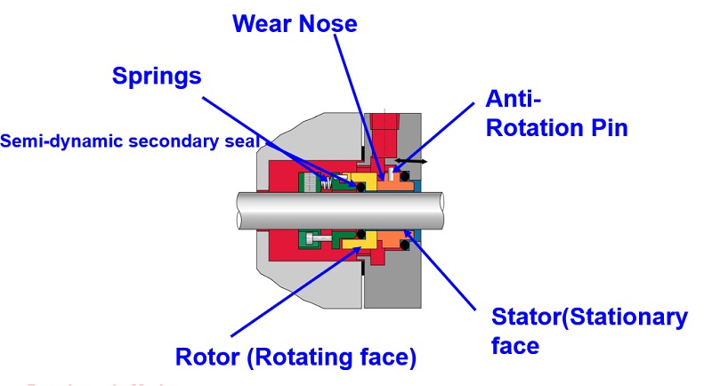
One is stationary and the other rotates against it to achieve a seal. There are several types of mechanical seals, ranging from simple single-spring designs to considerably more complex cartridge seals. The design, arrangement, and materials of construction are essentially determined by the pressure, temperature, speed of rotation, and product being sealed (the product media).
Mechanical seal failure is the greatest cause of pump downtime. Understanding how seals work and proper handling is beneficial for prolonging the lifespan of the seal and overall health of the machine. Here are some tips that will help you properly install and maintain mechanical seals, resulting in increased reliability.
• Treat mechanical seals like bearings.• Follow instructions from the manufacturer.• Use clean hands or gloves that are free of any grease or oil.• Keep seals away from any dust, debris, or lint.• Avoid dropping seals. Dropped seals generally need to be replaced.
Mechanical seals can last 2 to 10 years. In addition to proper handling and cleanliness, the following factors can have a negative impact on the lifespan of a seal:
Information for this article was provided by ACOEM Vibralign, Richmond, VA. For more information about mechanical seals, pump-shaft alignment, and precision-maintenance training, visitvibralign.com. Click here to download a poster about mechanical seal fundamentals.

Conducting root cause failure analysis on a failed mechanical seal can in the long run minimize mean time between failure (MTBF) and operating costs by preventing repeat premature failure. If you can find the culprit and resolve the issues, you can prolong the life of the next mechanical seal and save time and money.
A tremendous amount of useful information is available from a failed mechanical seal. With nothing more than your eyes and a measuring device like a dial or digital caliper, you can identify failure modes with great dependability and detail. With this information you can decide if any corrective measures are worth the resources required. In many cases, the payback is many times the outlay in a very short period of time.
And because RCFA (Root Cause Failure Analysis) provides evidence rather than conjecture, it can support the changes needed when other departments are involved. Following are the steps to examine a failed mechanical seal.
Whenever possible, examine shafts, sleeves, bearings, gaskets and other pump parts. Doing this, you can support your interpretation of what you see on the seal parts or even change it as necessary.
Knowing when the seal leaked narrows down the cause of failure. The critical division is whether the seal leaked when liquid was brought to it or before start up, or after the pump started running
Normal seal flatness is just 2 helium light-bands or 23 millionths of an inch! Corrective action here would be to test the seal assembly in a pressure testing rig before installation and/or to inspect the seal faces with a monochromatic light and an optical flat.
Most seals require a working length with only plus or minus .030” tolerance. The working length must come from the factory. There is almost no reliable method to determine the working length of a seal when in the field. This is one reason why cartridge (pre-measured) seals have become so popular.
If you have a PTFE wedge seal design, the wedge can be in backwards or be an incorrect size. An O-ring can be the wrong cord diameter. An O-ring groove could have been machined incorrectly.
Conversely, if the seal leaked after startup, it was not due to one or more of those four issues. You can eliminate these four issues and seek other causes.
This is the mark made by the mechanical seal rotating face rubbing against the stationary face. The seal faces are the lapped parts of the seal that rub against each other. The wear tracks may contain clues that may identify the reason the seal failed. Double seals will have two sets of rotary and stationary faces, so check them both (but keep each set together)
The working length of the seal must be provided by the supplier. It is almost impossible to determine the correct working length in the field. And, this is almost always just a plus or minus .030” tolerance.
If the pump is cavitating, the faces are literally blown apart then they come back together fast when the pressure drops. This jams the seal faces together.
If a pump is vertical, any entrained air will eventually makes its way to the highest point inside the pump. This is often where the seal faces are. If this happens, the faces run dry. Venting this area or having circulation will prevent this.
Broken springs are almost always a result of stress corrosion. This happens when stainless steel is flexed in the presence of halogens such as fluorine, bromine, iodine and others. Stress corrosion is actually a chemical attack where small cracks or fissures are created in the stainless steel. Particles can enter this crack and when the springs tries to compress a strong mechanical force is created that can break a spring. Most high-quality industrial mechanical seals have been converted to Hastelloy C springs. Hastelloy C can withstand halogens without cracking. It is interesting to know that springs and metal bellows can actually flex almost indefinitely without breaking if they are flexing within the limits of travel that they were designed for.
Clogged springs indicate that solids in the process flow have accumulated. Seals with multiple small springs are more prone to clog than seals with one large spring or metal bellows.
This chemical incompatibility could be from the process fluid itself. Keep in mind that chemicals become approximately twice as aggressive for every 20 degree rise in temperature. The stuffing box area of a pump can be several hundred degrees F higher than the temperature of the discharge. Additionally, the problem can be a flush fluid or even what a pump is cleaned with. For applications where there is no available elastomer that can handle the chemicals the sealing device will see, you can select a mechanical seal with either PTFE or flexible graphite secondary seals. Neither PTFE nor flexible graphite is a true elastomer. They are considered “plastic” in the sense that when deformed they do not recover their original shape.
Keep in mind that temperature limits published for various O-Ring materials are based on hot air only. These limits are for ultimate failure. Lower temperatures can start the degradation of an elastomer. Again, the temperature in a stuffing box can be hundreds of degrees F higher than at the discharge. Only a temperature gauge connected to the stuffing box, preferably with a tell-tale to indicate the highest temperature reached, can verify how hot the stuffing box gets. The solution for heat is either to reduce the temperature the mechanical seal and its O-Rings actually experience or to select an elastomer with suitable temperature resistance.
Measure the O-Rings from the inside to the outside and from the top to the bottom. This determines the actual deformation. Some deformation is normal. However, if the O-Ring is deformed to where your measurements are at or lower than the nominal dimensions, the O-Ring can no longer seal. Following is some specific dimensional information:

Mechanical seals prevent pumps from leaking by containing the pressure of the pumping process and withstanding the friction caused by the rotating shaft. This results in reliable operation, less wasted product, more cost savings and less cleanup. However, why do mechanical seals fail?
In many pump systems, a mechanical seal is the first component to fail. They are also the most common cause of pump downtime and account for more pump repair costs than any other part of a pump. Often, the seal is not to blame. Other culprits include:
Therefore, it is crucial they are installed and maintained properly to prevent failures. Teams must pinpoint the causes of each failure, but how do plant and maintenance managers isolate the root cause?
One option is to have a seal manufacturer perform a seal failure analysis. Some seal manufacturers perform complimentary seal analysis on any seal, not just theirs.
End users simply send their mechanical seal to the manufacturer’s engineering team. If multiple seals need to be analyzed, they may come on-site to perform the root cause analysis. Most reviews can be completed in about two weeks.
to take to prevent future failures. The experts who examine the seal can ensure the ideal seal for the application has been selected. If not, they will recommend alternate technologies.
The team will also help end users optimize their system conditions and achieve the best possible operation from their assets. Optimizing mechanical seal performance also improves shutdown to shutdown processes. This information, along with alternative proposals as needed, help end users prevent further failures and improve their return on investment (ROI). In summary, a sealing failure analysis:
seal failure. Something else happened to cause it. The story of what the seal experienced during operation before it failed can be revealed. An analysis may determine or confirm:
For instance, a stationary seal face is cracked, originating from the drive pin slot. Also, sticky residue has adhered to the face. This crack means something different than a stationary seal face with a crack located at a different position and product residue that is clean and not tacky.
Both cases would look the same on a simple table listing all the seal damage. However, the failure cause would be different. In the first example, the crack was caused by the product attempting to stick the rotary and stationary faces together. This adhesion caused increased torque on the stationary pin. This caused the stationary face to crack.
In the second example, the crack was likely caused by impact. This indicated the seal was not installed properly. Different symptom combinations reveal multiple failure modes.

1. Increase seal chamber pressure if it can be achieved within operating parameters (maintain at a minimum of 175kPa (25psig) above suction pressure)
Note: A review of seal balance requires accurate measurement of seal chamber pressure, temperature and product sample for vapor pressure determination.
Mechanical seal reliability is significantly affected by the operational characteristics of the flush system and its components. In services where the pumped fluid can contain solids, API 610 and API 682 both offer the option of using flush line strainers or cyclone separators.
Flush line strainers can become blocked resulting in immediate seal failure. Cyclone separator effectiveness is dependent on the relative density difference between the fluid and solid particles and the flush line piping (adequate slope for the debris drain line back to the pump suction).
Using an external clean flush, if available, or a dual pressurized seal arrangement will eliminate the need for flush line strainers and cyclone separators and ensure optimum mechanical seal MTBFs.
Flush line strainers and cyclone separators have been the cause of low seal MTBFs (less than 12 months) in many applications where the seal fluid contains solid particles. Eventual modification to a clean external flush or a dual pressurized seal has significantly increased seal MTBFs (greater than 48 months).
This best practice has been used since the 1990s to thoroughly investigate, with the process engineers, the possibility of using a clean external flush source in services where solid particles were contained in the seal fluid. A contingency recommendation where a clean external flush was not available was to use a dual pressurized seal.
In many cases, the additional cost of an external flush or dual pressurized seal was justified on the basis of past plant mechanical seal history and the loss of revenue when the standby pump was under maintenance and the operating pump failed.
Knowing the manufacture and model number of the mechanical seals and pumps at your plant is imperative when managing your plant. Carolina Seals offers an Equipment Survey program in which we will collect important data about equipment such as but not limited to: Equipment ID and service name, Type and mfg of mechanical seal, Single seal or Double seal, API piping plan, standard bore or large bore seal chambers, pump Mfg and Model #s, bearing isolators or lip seals, oil bath or grease, motor frame size, Horse power, & rpms. With help from the plant we can determine how critical each piece of equipment is and create an Excel spreadsheet listing the collected data. This spreadsheet will aid you in determining the following: Troubleshooting issues with pump & sealing specialist, Inventory of pump parts and mechanical seals, Establishing the average Mean Time Between Failure of your equipment and Identify bad actors.


 8613371530291