
api mechanical seal in stock
Plan 53B systems have been viewed as an “engineering challenge” around the world, often with long lead times. The innovative modular concept permits 12 modular options to be applied to create an API 53B System for any application. This modular process facilitates efficient stock control which in turn provides AESSEAL® API 53B Systems with rapid delivery times. Modularity eases the production of documentation for each Plan 53B product and also makes it easier to determine the correct solution for the application.
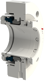
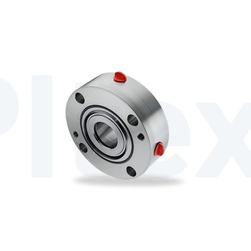
Pressurised barrier fluid circulation in outboard seal of dual seal configuration. Circulation is maintained by using pumping ring in running condition and with thermosyphon effect in stand still condition. The pressure is maintained in the seal circuit by a bladder accumulator.
The AESSEAL® API Type A, B and C single-seal range offers the user an unprecedented range of API engineered sealing solutions to suit all application requirements. The category 1, 2 and 3 seals are qualification tested to API 682. Modular design allows the users to select the right solution for their application, with the modular design ensuring simplicity of purchase and fast delivery.
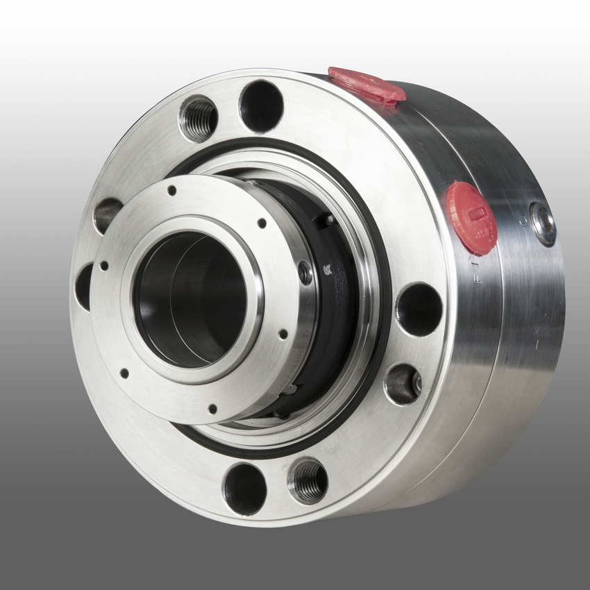
Thin cross-section (TXS) seal designs for mature asset installation including API 610, 5th Ed. with a 0.500" (12mm) radial cross-sectional space between the shaft and seal chamber
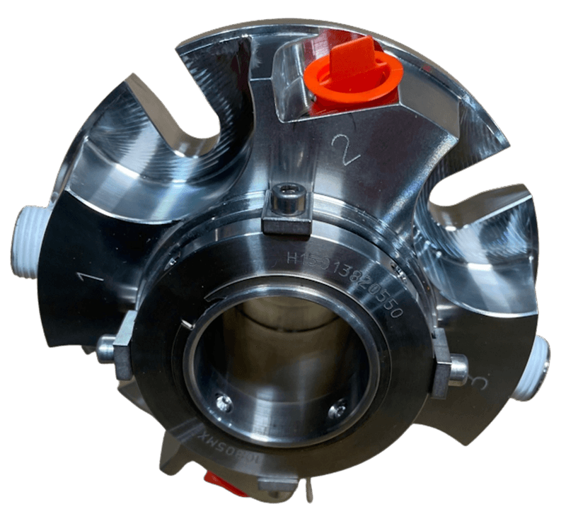
World-leading bi-directional pumping ring performance with 0.062” (1.5mm) radial clearance between rotor and stator; conforming with API 682 Section 8.6.2.3 without compromise
World-leading bi-directional pumping ring performance with 0.062” (1.5mm) clearance between rotor and stator, conforming with API 682 Section 8.6.2.3 without compromise
Also available CAPI-74 a face to face, category 2 & 3 seal. The CAPI-74 is a non-contacting dual seal designed for pumps meeting ANSI/API standard 682. Dual pressurized dry gas seals are becoming more common in the Oil and Gas industry and can provide zero process emissions in service. For more information visit the capi-74 product page
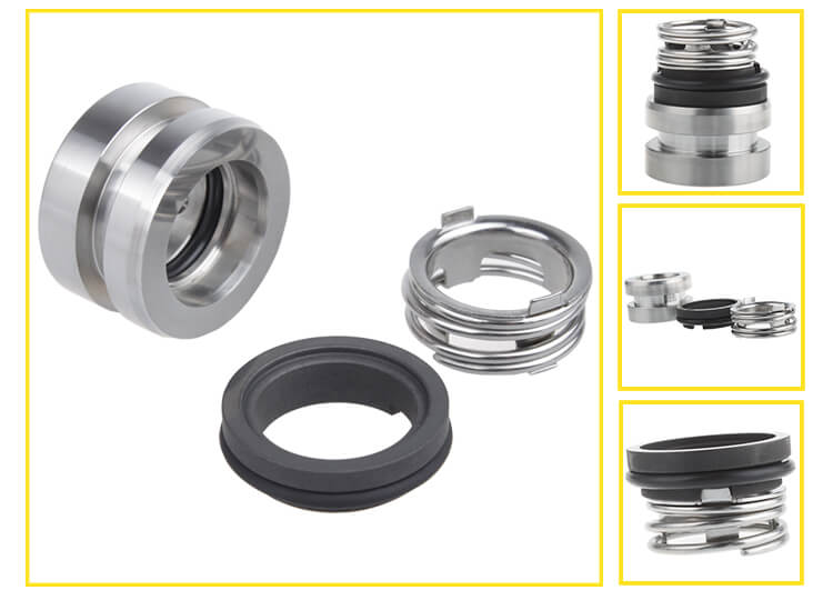
In many cases, Cartridge Seals may contain the exact same major items that are sold separately as Component Seals. These pieces include the Rotary Seal and Stationary Face as well as other minor parts like O-rings or Gaskets all required at assembly. The advantage of using a Cartridge Seal is that the time required for installation, and even more importantly, the possibility of error during installation is dramatically reduced. When installing a Cartridge Seal, the necessity of having to measure internal components positioning on the shaft to achieve proper face loading is eliminated. Cartridge Seals come pre-assembled from the factory with all internal components assembled with proper face loading and all pieces in place, exactly where they should be. Cartridge Seals eliminate the need to handle delicate, polished parts such as Seal Faces that can be compromised by the presence of dirt, smudges and oils that can result from handling during assembly. So, for the easiest and most reliable Seal installation, Cartridge Seals go a long way towards helping you achieve trouble free startup and extended service life from your equipment.

JCI Industries, Inc. is the exclusive provider of Flowserve Fluid Sealing Devices in Kansas, Western Missouri, and Nebraska. We offer a complete line of seals including cartridge seals, dry-running seals, metal bellows, elastomeric bellows, split seals and gas barrier seals for zero emissions.We also carry bearing protection devices and seal chamber auxiliary equipment.
We stock complete cartridge and component seals for all ANSI and API pumps, and maintain over $250,000 of seal related inventory. JCI’s seals specialist has 60+ years of experience, including seal application design & recommendation, seal failure analysis, and complete seal repair and installation.
Flowserve heritage product lines include BW/IP, Pacific Wietz, Durametallic, Five Star, and Pac-Seal. BW/IP was engineered API type seal, Pacific Wietz the gas seals came from, Durametallic and Five Star were the ANSI market seals and the Pac-Seal are for the OEM market.
In the past, external clean, cool fluid was used to lubricate seal faces or dual seals operating on clean barrier fluid. Now, the solution is to use Diamond Coated Silicon Carbide Faced Seal (UNCD) and let the process fluid itself lubricate the seal even with challenging applications.
Flowserve Mechanical Seal Piping Plan Flip Book – reference book that provides a concise summary of the most essential piping plans used successfully in today’s process plants. Each plan shows all the standard and optional auxiliary components referenced in API Standard 682
See improved performance of replacing John Crane Type 21 ™ with a Pac-Seal 21 utilizing a crimped-head rotary unit removing metal contact from the seal ring and preventing foreign material from collecting under the bellows.
Standard cartridge mechanical seals provide exceptional reliability and standardization in a wide variety of industrial applications and service conditions. ISC2 seals are designed to fit hundreds of pump and rotating equipment models from global manufacturers.
Application Guide: mechanical seals in product pipeline pumps, covering the transmission of crude oil and refined products such as fuel oils, gasolines, crude oils, and natural gas liquids (NGL), propane and ethane.
Pumping processes involving toxic or hazardous fluids that can’t risk leakage because of stringent environmental regulations require a double mechanical seal. Compared to a single mechanical seal, a double seal gives you significantly greater protection against leaks. With a double mechanical seal, you have an arrangement of two mechanical seals (a primary or inboard seal and a secondary or outboard seal) in series—back-to-back, tandem, or face-to-face. Each seal has a rotating (R) surface and a stationary (S) seal surface. These seals can be arranged in one of three patterns.
In a back-to-back arrangement, the stationary seal faces are positioned back-to-back with the rotating seal faces on the outside. The back-to-back arrangement is easy to install and used for many general pumping applications.
The tandem arrangement has the two pairs of seals mounted with the same orientation. This arrangement is preferred for toxic or hazardous applications because the outboard seal provides full pressure back-up, allowing the outboard seal to back up in the event of an inboard seal failure.
In the face-to-face arrangement, the rotating seal faces share a common stationary seal face. This arrangement is useful when equipment space is too constrained to permit back-to-back or tandem seal arrangements.
The American Petroleum Institute (API) Standard 682 classifies double mechanical seals into two configurations—pressurized and unpressurized. The pressurized arrangement has a barrier fluid delivered to the double mechanical seal by a seal support system. The barrier fluid is delivered at a higher pressure than the process fluid and must be chemically compatible with the process fluid as it will lubricate the inboard seal faces and mix with the process fluid. The unpressurized arrangement has a buffer fluid delivered to the double mechanical seal by a seal support system. The buffer fluid is delivered at a lower pressure than the process fluid.
The barrier and buffer fluids you use can be liquid or gas. They provide lubrication and help maintain the required operating temperature of the seal faces. The typical choices are water and water/glycol mixtures, low-viscosity petroleum or synthetic oils, kerosene, diesel, and nitrogen.
To gain a better understanding of the differences between the uses of barrier and buffer fluids, let’s look at two common API plans for double mechanical seals—API Plan 52 Buffer Fluid Seal Pot and API Plan 53A Barrier Fluid Seal Pot Pressurized by Nitrogen.
API Plan 52 takes buffer (unpressurized) fluid from a reservoir (seal pot), delivers it to the seal chamber, circulates it between the inboard and outboard seals using a pumping ring located driven by shaft rotation, then returns the fluid to the reservoir. In the event of an inboard seal failure, process fluid leaks into the seal chamber. When that occurs an increase in buffer fluid pressure and/or level alerts operators to the problem. The outboard seal, however, contains leakage until maintenance can replace the damaged seal.
This plan can include cooling coils in the reservoir to maintain the required buffer fluid temperature, visual or mechanical fluid level indicators, pressure and level transmitters, and connection to a collection system and buffer fluid replenishment source.
The overall design of this API plan for a double mechanical seal is relatively simple in comparison to other plans. Design decisions involving tubing size, length, geometry, type (carbon vs stainless steel), buffer fluid type, and volume of the buffer fluid reservoir are critical in maintaining the proper operating environment for the double seal. If you don’t have this expertise in-house, work with an experienced, local seal support system vendor to ensure the API Plan 52 is designed to meet your specific pumping requirements.
API Plan 53A is conceptually similar to API Plan 52 with the difference that the fluid being circulated between the double mechanical seals is under pressure. A pumping ring is used to circulate the fluid. The reservoir that contains the barrier fluid is pressurized by plant nitrogen. Reservoir pressure should be set a minimum of 20 to 25 psi (1.4 to 1.73 bar) above the maximum seal chamber pressure, allowing the barrier fluid to leak (and lubricate) across the inboard seal faces into the process fluid. For this reason, the barrier fluid must be chemically compatible with the process fluid.
Because barrier fluid is depleted as it moves across the inboard seal faces, it needs to be replenished. This can be done manually or automatically by way of a system that serves multiple pumps. API Plan 53A design options include reservoir type and volume, cooling coils, fluid level and pressure indicators, and transmitters to alert to level or pressure changes that indicate seal failure.
When you choose an API plan for a double mechanical seal, your primary decision is between a buffer or barrier plan. I’ve highlighted two of the API plans for double mechanical seals above to show the basic differences. There are multiple API plans for double mechanical seals to choose from—pressurization from bladder or piston accumulators, plant nitrogen delivered directly to the seal chamber, and custom-engineered external systems. Your choice will be determined by the process fluid and pumping conditions and the type of double mechanical seal your vendor recommends.
With this information in hand, it’s best to work with an experienced local seal support system vendor. They’ll be able to meet with you on-site to review the specifications for the pumping process, the pump, and the double mechanical seal. They’ll evaluate your existing infrastructure and its influence on seal support system design. Based on this information, they’ll then design the seal support system to meet the specific pumping requirements.
If you work with a global vendor like Swagelok, based on the design, we can quickly assemble and thoroughly test the API plan at our local facilities prior to delivery. We’re also conveniently available for follow-up consultations, on-site, remotely, or by way of a quick phone call.
For well over 50 years, Swagelok has worked closely with Northern California process industries to confidently choose the right API plans for pumping needs. Our locally based Field Engineers and certified technicians provide field verification of your seal support requirements, designs based on best practices gained from global experience.
To find out more about howSwagelok Northern California can help you choose the right API plan for double mechanical seals, as well as process and atmospheric side seals,contact our team today by calling
Morgan holds a B.S. in Mechanical Engineering from the University of California at Santa Barbara. He is certified in Section IX, Grab Sample Panel Configuration, and Mechanical Efficiency Program Specification (API 682). He is also well-versed in B31.3 Process Piping Code. Before joining Swagelok Northern California, he was a Manufacturing Engineer at Sierra Instruments, primarily focused on capillary thermal meters for the semiconductor industry (ASML).

A sealing system, consisting of a mechanical seal and an associated supply system that is balanced by individual applications, is the utmost guarantee for a reliable sealing point and uninterrupted pump service. The performance of the seal is greatly influenced by the environment around the seal faces, making the provision of suitable, clean fluids as well as a moderate temperature an essential topic.
This guiding booklet provides a condensed overview of all piping plans established by the API 682 4th edition guidelines. Each illustrated piping plan is briefly described, and a recommendation that considers the media characteristics in terms of the relevant application and corresponding configurations is given to help you reliably select your sealing system. Furthermore, the content of this booklet has been enriched by providing clues – so-called ‘remarks and checkpoints’ – where EagleBurgmann shares the experiences gained from multiple equipped plants.
Several factors play a major role when choosing the product, the product type, the materials used and how it is operated: process conditions at the sealing location, operating conditions and the medium to be sealed.
No matter what requirements our customers have, EagleBurgmann understands how these factors affect functionality and economic viability, and they translate this expertise into outstanding long-term, reliable sealing solutions. EagleBurgmann has all the expertise needed to manage and support the entire development, life and service cycle of its sealing solutions.
EagleBurgmann offers customers the widest product portfolio of seals and seal supply systems according to API 682 4th edition. The configurations listed for each individual piping plan are to be understood as recommendations including possible utilizations which may also be applied.
EagleBurgmann is one of the internationally leading companies for industrial sealing technology. Their products are used wherever safety and reliability are important: in the oil and gas industry, refining technology, the petrochemical, chemical and pharmaceutical industries, food processing, power, water, mining, pulp & paper and many others. More than 6,000 employees contribute their ideas, solutions and commitment towards ensuring that customers all over the world can rely on their seals and services. More than 21,000 EagleBurgmann API-seals and systems are installed world-wide.
John Crane brings you the world’s most complete selection of performance-proven edge-welded and formed metal bellows sealing products used in a wide range of rotating equipment such as pumps, compressors, mixers, and agitators. Our experience in diverse industries such as oil & gas, petrochemical, chemical, refrigeration compressor, pharmaceutical, food processing, pulp & paper, and more have proven the soundness of John Crane’s metal bellows design.

Mechanical seal failure due to unfavorable operating conditions is an issue in every industry. Double mechanical seals especially require proper sealing accessories to create suitable operating environments which are key to increasing MTBF. Reservoir systems are one of the most common and effective options to supply cooling fluid crucial to successful seal operation.
A double -or dual – cartridge seal is defined as an arrangement of two mechanical seals in a series. These seals may be configured in various orientations within the cartridge. The seals themselves are referred to as the “primary” (or inboard) seal and the “secondary” (or outboard) seal. A double seal arrangement is the superior option to a single cartridge when it is imperative the product being pumped does not leak into the atmosphere. The API (American Petroleum Institute) Standard 682 classifies dual seals into two configurations. These configurations also apply to ASME (American Society of Engineers) B73.1 and ASME B73.2 pump designs.
Arrangement 2 (Unpressurized) Designs: the buffer fluid is the operating environment for the secondary seal and forms a “buffer” between the process fluid and the atmosphere.
Arrangement 3 (Pressurized) Designs: the barrier fluid is the operating environment for both the inboard and outboard seal, preventing process leakage to the atmosphere.
Buffer and barrier fluids may be either liquid or gas. These fluids lubricate seal faces during operation as well as regulate operating temperatures by moving heat—both generated and absorbed—away from the faces.
Seal support systems are necessary for the smooth operation of a dual mechanical seal. Here are two of the most common piping plans for these systems.
This is an unpressurized system consisting of a reservoir, supply and return lines, and an internal circulation device within the outer seal (commonly referred to as a pumping ring). The buffer fluid circulation rate is dependent on how this circulation device functions during seal operation.
Reservoirs may be fitted with a variety of measurement devices such as a liquid level indicator and pressure gauges as well as valves and switches to aid in various operation and maintenance functions. For instance, a typical support system configuration for natural gas liquids (NGL) would issue an alarm (visual, audible, or both) when the inner seal fails. In addition, the outer seal would take over the primary seal function until maintenance is performed.
This system forces gas from an external pressurized source into the reservoir to pressurize the barrier fluid. This means the reservoir pressure will be above seal chamber pressure; a guideline is a minimum of 20 to 25 psig (1.4 to 1.73 bar) above the maximum process pressure.
The Plan 53A is also used to maintain a specific operating temperature range to ensure optimum lubrication at the seal faces. The reservoir houses a cooling coil which actively cools the barrier fluid as necessary.
As with the Plan 52, a circulation device is used to move the barrier fluid. Replenishing a Plan 53A system with fresh barrier fluid can be as simple as a using a hand pump or a more complex arrangement which satisfies multiple seals.
Liquid-lubricated dual mechanical seals require an external source of clean, cool lubricating fluid. The following fluid reservoir systems create this enhanced sealing environment, enabling longer operational life for dual seals.
In the oil and gas industry, reliable seal operation is critical to running efficient, safe processes. In conjunction with API 682 Piping Plans 52 and 53A, seal support systems aid in smooth seal operation.
If you require an engineered seal support system or are interested in additional options to Flexaseal’s ANSI PLUS and ANSI LITE support systems, please contact our applications engineering team.
Swagelok’s standard designs can quickly and easily be configured to meet your specific needs whether single-seal, dual-seal, quench or gas seal. Our plans meet API 682 standards that support the use of tubing instead of piping, reducing potential leak points and providing enhanced vibration resistance.
Watch episode 5 of Swaging with Garyas he interviews Technical Advisor JakeJones, a former millwright, and I&E tech and planner, with one of the largest rubber plants on the Gulf Coast about the benefits of Swagelok"s Seal Support Systems.
Kits adhere to API best practices by showing technicians where to bend tubing to eliminate potential leak points through the reduction of elbow fittings and pipe threads.
At ProSeal Service Group, state-of-the-art mechanical seal products are a way of life. After more than two decades, our partnership with AESSEAL®—a world specialist in mechanical seal R&D—has granted us exclusive rights to distribute in Michigan, Ohio, and Alaska. This allows us to deliver some of the most technologically advanced seal products in Component, Single Cartridge, Double Cartridge, Split, Metal Bellows, Mixer, and API seals to keep you operational.
In addition to cutting-edge modular mechanical seals, we specialize in bearing protectors, gasketing products, and gland packings. All of ProSeal’s products are designed to limit operational and maintenance costs throughout the lifetime of your equipment for maximum ROI. From double bellows to single pushers, we can help you find and maintain the right mechanical seal products for your operation.
Here’s an interesting little anecdote that I was told many years ago. I may not have it quite right and, for all I know, it may not even be true, but here goes. In the 1970s, I was told that very long ago, the practice was to test pumps at 2 x MAWP. Perhaps this was because pumps are manufactured from castings. Anyway, there was a pump standards meeting (perhaps this was even an early form of an API standards meeting) and a requirement was written to hydrostatically test pumps at 1.5 x MAWP. After the meeting, the chief engineer for a major pump manufacturer was buying drinks for everyone at the bar. Surprised by his generosity, a fellow committee member remarked that the 2x hydrostatic test must have been difficult. “Not at all”, said the chief engineer, “In fact, I just increased all my pressure ratings by 33%!” That is, pumps previously rated for 600 psig MAWP but hydrostatically tested at 1200 psig could still be hydrostatically tested at 1200 psig but then rated for 800 psig MAWP!
I’ve been told that the multiplication factor for determining the hydrostatic test pressure will be changed from 1.5 to 1.3 according to the ASME Pressure Vessel Code Section VIII. Apparently this will be applied to both pumps and piping. The same multiplier will probably be used for API 682 reservoirs such as are used with Piping Plan 52 and 53. The pertinent 4th Edition clauses for reservoirs now read:
Pipe based reservoirs for API 682 sealing systems must be built entirely of piping components and ASME B31.3, “Process Piping”, (ISO 15649) is the governing standard. As far as I can tell, ASME B31.3 now requires hydrostatic testing at 1.3 x MAWP.
It should be noted that the mechanical seal is not considered to be part of the pump pressure vessel and therefore does not fall under the pressure vessel rules. Seal manufacturers have several pressure ratings for their products. API 682 recognizes a static pressure rating, a dynamic pressure rating and a hydrostatic pressure test rating (see the SealFAQs version of these definitions). Each seal OEM seems to use a different and proprietary method for determining these pressure limits.
Several new piping plans have been introduced in the second edition. These include additional options for dual pressurized liquid seals as well as new piping plans to support containment seals and dual pressurized gas seals.
Plan 14. This plan is a combination of Plan 11 and Plan 13. This was introduced in API-610 8th edition and is now included in API-682. This plan is primarily used in vertical pumps to allow for injection into the seal chamber while continually venting the seal chamber back to suction. (Figure 2)
Plan 53.This plan is used to provide pressurized barrier fluid to Arrangement 3 seals. In the first edition, this was shown as a pressurized reservoir. While this style of Plan 53 is commonly used, other variations do exist. These variations have not had an official designation but have assumed names like “Plan 53 Modified”. The second edition has defined three variations of Plan 53 and uses the designations Plan 53A, Plan 53B, and Plan 53C. If the user wishes to specify a specific variation, they can use these designations. If the user does not specify a specific variation and uses the term Plan 53, any of the variations are considered acceptable.
Plan 53A.This plan is the same as Plan 53 in the first edition of API 682. An externally supplied gas such as nitrogen pressurizes a barrier fluid reservoir. Barrier fluid is pumped from the seal to the reservoir by a pumping device on the seal and flows back to the seal by gravity. An advantage of this system is that cooling coils can be provided in the reservoir. Combined with the large volume of fluid in the circulation system, fluid conditions remain very stable. Barrier fluid pressure can also be controlled very accurately with a pressure regulator on the nitrogen line. The disadvantage of this system is that, at high pressures, the pressurization gas can dissolve into the barrier fluid. This may cause instability in the seals. (Figure 3)
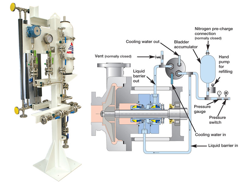
Plan 53B. This plan uses a small closed loop without a reservoir. Barrier fluid is pumped into the loop by a pumping device and is circulated back to the seal. In most cases a seal cooler (either air-cooled or water-cooled) is placed in the loop to control the barrier fluid temperature. A bladder accumulator that is connected to the loop pressurizes the barrier fluid. The accumulator serves the dual role of providing make-up fluid and pressurization to the loop. This accumulator is pressurized so leakage from the loop does not drop the barrier fluid pressure below the seal chamber pressure. The advantage of this system is that it can be used at high pressure without pressurization gases dissolving into the barrier fluid. It is also common to use this system in areas where cooling water is not available and air-cooled seal coolers must be used. The disadvantage is that the accumulator must be sized adequately to prevent large pressure fluctuations due to seal leakage and an external seal cooler must be provided. These can make this variation more expensive than Plan 53A. (Figure 4)
Plan 53C.This plan also uses a small closed loop without a reservoir. Barrier fluid is pumped into the loop by a pumping device and is circulated back to the seal. A piston accumulator that is connected to the loop pressurizes the barrier fluid. The accumulator serves the dual role of providing make-up fluid and pressurization to the loop. The piston accumulator is designed to take a reference pressure line (generally off of the seal chamber) and provide a higher pressure into the barrier fluid loop. Because of the design of the accumulator, the pressurization of the loop is at some constant ratio over the reference pressure (e.g. 1:1.15). The advantage of this system is that the pump pressurizes the loop and no external gas supply is required. The system automatically tracks the pressure in the seal chamber to compensate for variations in pump operating conditions. The system can be operated at high pressures without dissolving pressurization gas into barrier fluid. A disadvantages is that the piston accumulator is exposed to pump fluid. It is therefore exposed to corrosion and contamination from the pump process. It is also generally more expensive than a Plan 53A. (Figure 5)
Plan 71. This plan is designed for dry running containment seals. Ports are provided for buffer gas but are plugged during installation. This plan is used when barrier gas may be required in the future. (Figure 6)
Plan 72. This plan is designed for dry running containment seals (2CW-CS and 2NC-CS). A buffer gas is supplied to the containment seal chamber to sweep leakage from the seal to a collection system. The buffer gas pressure is lower than seal chamber pressure. The plan describes a control panel to filter the buffer gas, regulate the pressure, and provide instrumentation to monitor operation. (Figure 7)
Plan 74. This plan is designed for dual pressurized gas seals (3NC-FB, 3NC-BB, and 3NC-FF). A barrier gas is supplied at a pressure higher than seal chamber pressure. The plan describes a control panel to filter the barrier gas, regulate the pressure, and provide instrumentation to monitor operation. (Figure 8)
Plan 75. This plan is used for dry running containment seals (2CW-CS and 2NC-CS). This plan is designed for applications where leakage past the primary seal does not completely vaporize. Leakage is piped from the containment seal chamber to collection chamber where liquid and gas phases of the leakage are separated. (Figure 9)
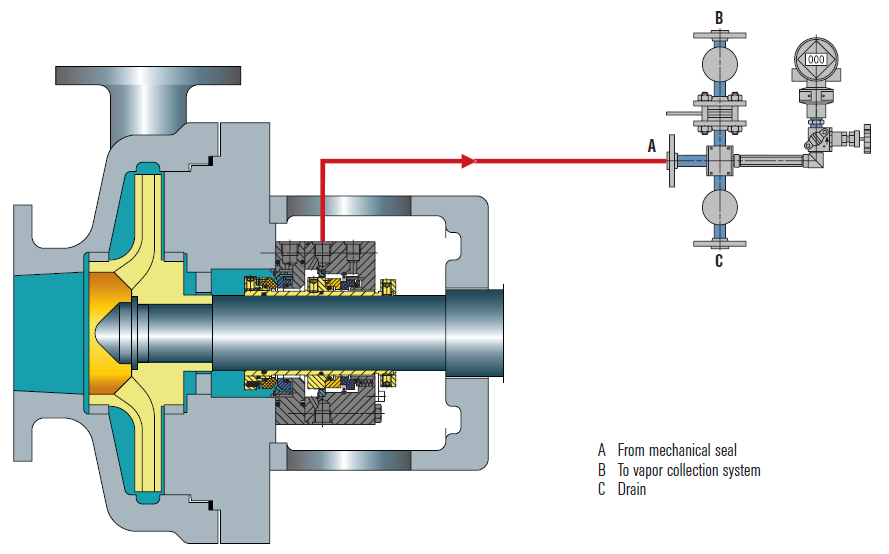
Plan 76. This plan is used for dry running containment seals (2CW-CS and 2NC-CS). This plan is designed for applications where the leakage past the primary seal completely vaporizes. Vapors are collected and piped to a vapor recovery system. (Figure 10)


 8613371530291