
api mechanical seal plans price
I am sorry. I can"t answer your question. You should contact a mechanical seal manufacturer and give them some "average" conditions such as seal size, service, metalurgy, etc. As I intended to say above, there are far too many variable to give a reasonable answer.
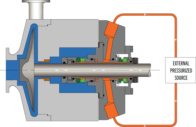
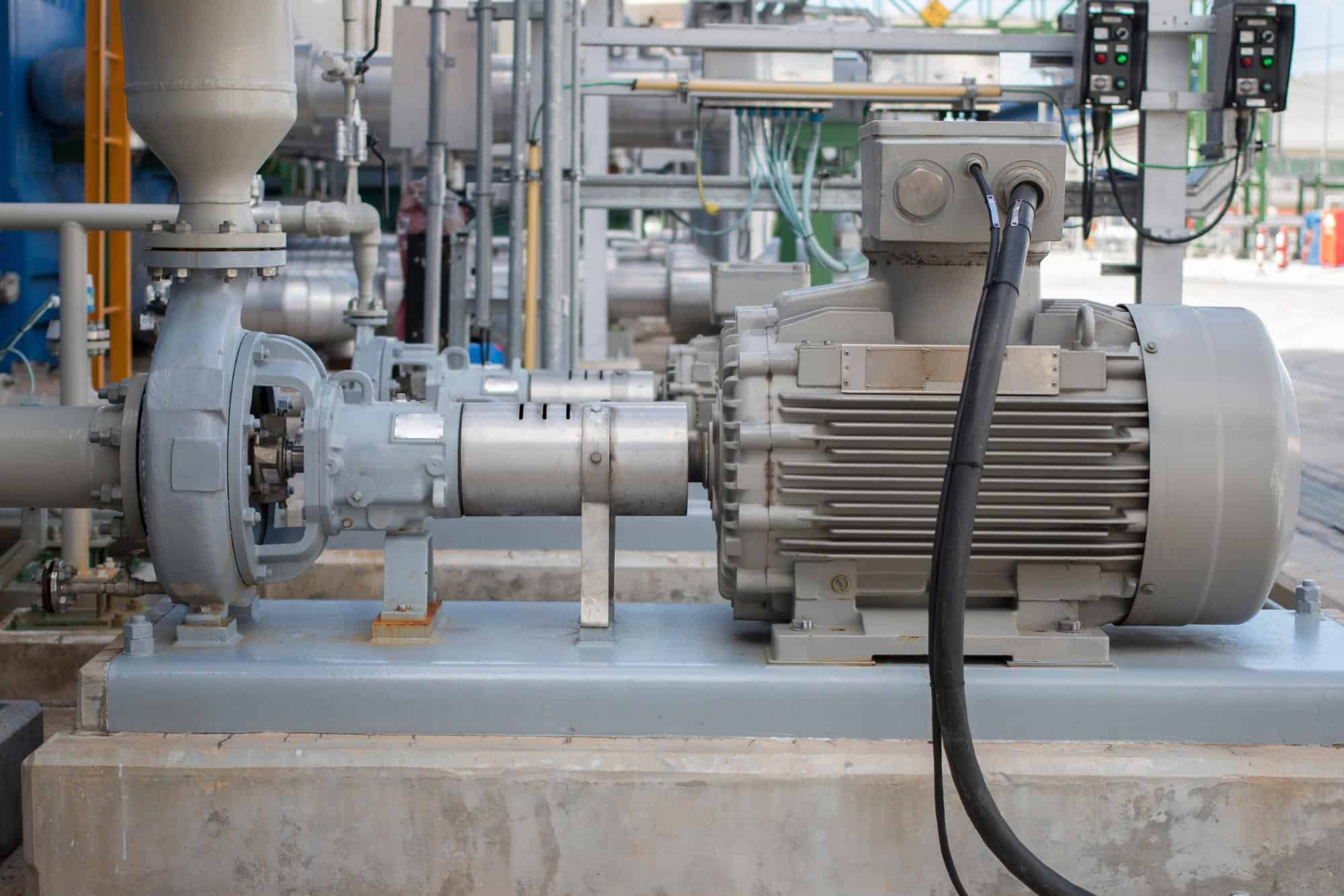
Pressurised barrier fluid circulation in outboard seal of dual seal configuration through a seal support system. Circulation is maintained by using pumping ring in running condition and with thermosyphon effect in stand still condition.

Several operational variables must be considered when choosing an API 682 piping plan for dual pressurized seals. These variables include flow rate, heat load, normal operating pressure, the number of mechanical seals to be serviced, and available utility requirements. Each seal support system will have advantages and disadvantages in relation to the variable operating conditions of API 682 Plan 53B and Plan 54 piping plans. Each application should be evaluated on a case-by-case basis for mechanical seal longevity and reliability.
A Plan 53B system utilizes a bladder accumulator to provide a typical operating pressure of 30- 50 psi above maximum seal chamber pressure when servicing one mechanical seal per system. The bladder accumulator prevents gas entrainment for operating pressures above 200 psi. The bladder is pre-charged with nitrogen using a charging kit and Schrader valve (like a car tire) and creates a separation between the nitrogen source and seal support barrier fluid. As a mechanical seal leaks barrier fluid into the process fluid, the operating pressure will drop until an alarm signals personnel to refill the unit until normal operating barrier pressure is returned. A refill period of 20 – 30 days is targeted and is based on bladder accumulator size (5, 10, or 15 gallons), seal leakage, and normal operating pressure.
Higher barrier pressure differential operating pressures above maximum seal chamber pressure will increase available usable fluid. Specifications requiring an increase from 50 to 100 psi above maximum seal chamber pressure will result in an increased time period before re-filling, assuming the usable fluid increase is not exceeded by an increase in seal leakage. However, the higher seal face leakage and increased heat generation which may occur at a higher barrier pressure differential must be accounted for in the mechanical seal / seal support design. Barrier differential pressures above 100 psi over maximum seal chamber pressure are not recommended due to diminishing returns between heat generation and increased leakage rates.
Plan 53B systems have an estimated maximum heat removal rate of 8,000 – 12,000 BTU/HR for target barrier fluid supply temperatures of 120°F. As heat removal rates exceed 12,000 BTU/HR, target temperatures and other seal support piping plans can be evaluated on a case-by-case basis.
Other factors to consider are flow rate and fluid circulation: either can be achieved by utilizing a pumping ring or an external gear pump. Pumping designs without pumping rings will require an external mag-driven positive displacement gear pump with typical flow rates of 1 to 3 GPM and can be less cost effective when compared to a Plan 54. A Plan 53B with an external gear pump is a closed loop system requiring the external pump to have the same pressure on suction as discharge. Appropriately-sized entry glands to and from the seal as well as the limited use of elbows should be utilized to prevent a differential pressure of 75 psi maximum between the lubricator pump suction and discharge, otherwise the lubricator pump can decouple. A Plan 54 is an open loop system with an atmospheric tank and filler/breather. Depending on the main pumping process, a Plan 53B closed loop system may be optimal for containment purposes with respect to environmental health and safety concerns in the event of a system upset.
An API 682 Plan 54 is available for those applications where operating capabilities such as flow rates, heat load requirements, normal operating pressures, and seal-per-system limitations exceed acceptable Plan 53B guidelines. The Plan 54’s normal operating pressure remains constant in relation to seal leakage unlike a Plan 53B where normal operating pressure decreases with leakage.
One Plan 54 can service one or multiple mechanical seals. When multiple systems are serviced by one Plan 54, all these systems must be evaluated for critical operation in the event of system failure. If deemed necessary, a redundancy plan to prevent system failure can be included in the design. Redundancy equipment can include primary and back up lubricator pumps, duplex filter assemblies, and dual heat exchangers. Multiple mechanical seals can be isolated and serviced without shut down, allowing other equipment to remain online and operational. A secondary power supply – when available – is recommended for a backup pump motor in event of main power disruption.
The Plan 54 holds a specific advantage over Plans 53 A/B/C because location proximity to the main pump is not required. In addition, Plan 54 selection is driven by shaft speed, circulation device limitations, and heat load. These specifications differ from the Plan 53 series’ required circulation rate which relies on size, circulation device, and piping to cool and lubricate mechanical seals.
A Plan 54 operates 30 – 50 psi above maximum seal chamber pressure and remains constant. For seal chamber pressure fluctuations, plan equipment can include digital pressure tracking control to maintain a 30 – 50 psi bias versus using constant pressure regulators. A pressure transmitter on the seal chamber references a pressure transmitter on the Plan 54 system to maintain a bias through DCS. Alternatively, using a pressure tracking mechanical valve with a reference line to seal chamber can maintain bias through mechanical means.
Simplex or duplex filter assembly options are included. Duplex filter assemblies allow elements to be changed while unit is running and operational. Differential pressure instrumentation is included for monitoring element condition and signaling when the element should be replaced. Filter assemblies can be upstream or downstream of the mechanical seal. Typical arrangement downstream is under atmospheric conditions. Placement on supply is required to meet the pump protection valve setting.
Transmitters or mechanical switch instrumentation is offered for equipment monitoring. Alarm logic for level, pressure, flow, and temperature is typical. Considerations for alarm logic is based on system complexity or the number of seals on the system.
Lastly, a Plan 54 can be equipped with a bladder accumulator safety package. Located upstream, the package includes a bladder accumulator and check valve on supply. The downstream package includes a normally closed solenoid or actuating ball valve on return. The solenoid can receive a signal to fail closed, maintaining a positive pressure for short periods of time which may be hours or days depending on seal leakage rate. This prevents reverse pressurization during upset and allows time for trouble shooting.
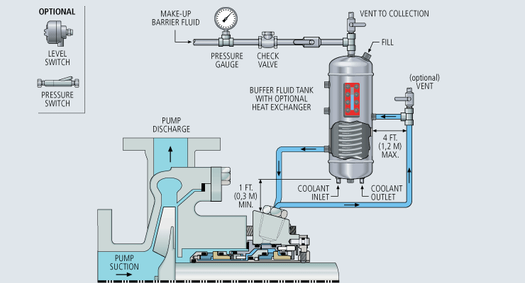
Pumping processes involving hazardous or toxic fluids often utilize dual mechanical seals to ensure operator safety and compliance with environmental regulations. The American Petroleum Institute (API) Standard 682 classifies dual mechanical seals into two categories— pressured and unpressured. For unpressurized configurations, a seal flush system, such as API Plan 52, is required for the seal to operate. A buffer fluid is circulated between the inboard and outboard seals to form a “buffer” between the process fluid and environment.
API Plan 52 seal systems are the most commonly used pressurized dual mechanical seal flush systems in Canadian operations. Plan 52 is widely used in oil and gas operations, but can also be used in chemical and petrochemical refining and power generation applications. Let’s take a look into how the API Plan 52 seal system works for centrifugal pumps and applications in oil and gas, chemical and petrochemical refinement, and power generation.
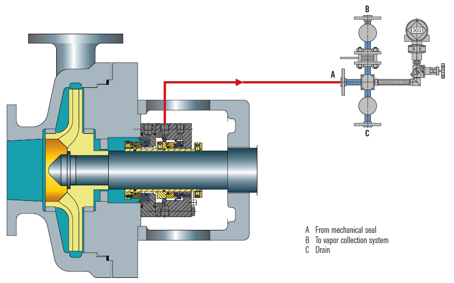
API Plan 52 seal systems employ a seal pot (reservoir) to deliver an unpressurized buffer fluid to the seal chamber and circulate the fluid between the inboard and outboard mechanical seals. A pumping ring is utilized to provide positive circulation through the seal flush system and into the seal. This plan is commonly used with light hydrocarbons or fluids with a high vapour pressure.
In the event of an inboard seal failure, process fluid will leak into the seal chamber, mixing with the buffer fluid. Thus, the selected buffer fluid must be compatible with the process fluid. One challenge with this plan is frictional losses in the buffer fluid inlet and outlet lines. Frictional losses may be minimized through properly selecting tube size, using large radius and/or 45-degree bends, and reducing the length of tubing in the design.
Tubing configuration and geometry, materials of construction, buffer fluid type, and seal pot volume can be determined and configured based on specific pumping and mechanical seal requirements. API Plan 52 seal systems can include cooling coils within the reservoir to maintain the temperature of buffer fluid being delivered to the seal chamber. This plan can also include instrumentation, such as pressure transmitters, level transmitters, and thermometers depending on the given application. Fluid systems vendors should be consulted to determine configuration specifics such as those listed above.
Depending on the application of dual mechanical seal flush systems, there may be benefits in the higher standards of an ASME stamped seal pot as opposed to a seal pot that meets a lower piping standard. ASME stamped vessels can be more easily tracked and maintained through their Canadian Registration Number (CRN).
In oil and gas operations, including steam-assisted gravity drainage (SAGD), API plan 52 can be used for dual mechanical seals for centrifugal pumps in upstream, midstream, and downstream operations with either high vapour pressure or lower vapour pressure fluids. In chemical plants and petrochemical refineries, dual mechanical seals may be used for high vapour pressure fluid applications. For chemical plants where chemicals are extremely hazardous, a more robust sealing system may be implemented. For power generation, API Plan 52 may be used for water pumping applications, such as boiler feedwater pumps and water treatment pumps.
Whether you are looking to implement a new custom-configured API Plan 52 seal system—or you are looking to upgrade your current plan—Field Advisors at Edmonton Valve & Fitting can provide expert consultations to determine how to increase pumping reliability and efficiency. We are well-versed in local pumping applications for industries including oil and gas, chemical and petrochemical refining, and power generation. We also offer ASME stamped seal pots for customers who would like to ensure proper testing and maintenance tracking with a CRN.
To find out more about how Edmonton Valve & Fittingcan provide API Plan 52 seal systems equipped with ASME stamped seal pots, contact our team of advisorsthrough our website or by calling 780-437-0640.
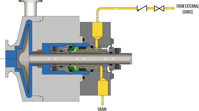
To correctly configure an API Plan 32 and flush flow rate, you’ll need to understand the role the plan plays. If process fluid can damage seal faces, API Plan 32 isolates the mechanical seal from potential damage. If the process fluid is toxic or hazardous, API Plan 32 reduces the risk of process fluid leaking into the atmosphere. If you’re pumping high-temperature process fluids, API Plan 32 helps cool the seal chamber and mechanical seal.
Regardless of why you’re implementing API Plan 32, you’ll need to determine the correct seal flush flow rate. Too little fluid flow and you’re undermining the reliability of the mechanical seal. Too much fluid flow and you’re driving up operating costs by consuming more flush fluid than required.
When you’re installing an API Plan 32 to isolate the mechanical seal from the process fluid, you’ll want to deliver flush fluid at a velocity or pressure that prevents process fluid from migrating past the throat bushing into the seal chamber. You can start by checking the recommended flow rates under different conditions provided by the mechanical seal manufacturer.
Even better, your asset management system may have detailed records regarding pump types, process conditions, and API Plan 32 seal flush flow rates. This information is often the most practical way to determine the correct flow rate to achieve both the required flow across the seal faces and velocity across the throat bushing.
If you don"t have this information at hand, there are some metrics that can get you on the right track. A target of 15 fps across the throat bushing is a good starting point to protect seal faces from process fluid. You may want to adjust that based on impeller shaft, bushing size and diametrical clearance, and volumetric flow rate past the shaft. Tighter bushing clearances will reduce flow rates.
If you decide to adjust the flush flow rate based solely on pressure, adjust it relative to seal chamber pressure. One approach recommends adjusting the flow by opening up the seal flush until the seal chamber pressure increases at least 10 psi. It’s not uncommon to increase the pressure beyond that, even approaching 25 psi above seal chamber pressure.
Another approach recommends a flush flow rate of 1 gpm for each inch of mechanical seal diameter for pumps running 3600 rpm. Regardless of the method you choose, you’ll want to limit flow rate to the lowest required to maintain seal reliability and minimize operating costs.
In addition to isolating the seal chamber from process fluid, mechanical seal friction or high-temperature applications may require a higher flush flow rate than calculated solely for isolation purposes. If the process is close to its boiling point, allocate no more than one-quarter of the available flush fluid temperature margin when calculating the flow rate.
As you can see, determining the correct API Plan 32 flush flow rate involves careful consideration of multiple factors. Beginning with the purpose for choosing the plan—isolation and/or heat removal—you’ll also need to factor in:
If you’re experiencing problems with pumps supported by API Plan 32 and don’t have the in-house expertise to quickly diagnose the problem, a local, experienced fluid systems field engineer can provide you with the needed guidance. Their experience in understanding how process conditions and flush fluid properties influence seal support system design is critical in determining the proper seal flush flow rate.
With their guidance, you’ll arrive at an API Plan 32 seal flush flow rate that maintains the proper seal chamber environment to prevent mechanical seal damage while minimizing the associated operating costs.
For more than five decades, Swagelok has been a key partner in providing expertise and guidance in the use of seal support systems for Northern California process industries. Our field engineers are available to meet onsite to assess your needs, recommend seal support systems specifically configured for your pumping processes, and fabricate and test the systems in our local facilities before delivering them.
To find out more about howSwagelok Northern California can assist you in determining the right API Plan 32 seal flush flow rate or help in designing seal support systems that boost pump reliability,contact our team today by calling
Single mechanical seal plans (API 682 Plans 11-41) are strategic tube and pipe arrangements that circulate fluid to or from your seal chamber to preserve appropriate lubrication, pressure, temperature, and particulate conditions. The term "plan" is the preferred term by API 682 (4th edition) to indicate "an arrangement of components." Single Mechanical Seal Plans are located on the process side of the seal, with the purpose of extending seal life and keeping process fluid emissions low. These plans typically depend on redirecting fluid to or from the seal chamber by using Swagelok components, tubing and other controlling equipment.

John Crane understands that reliable seal performance is needed to maximize process efficiencies while meeting production constraints, and we know that dependable fluid control systems are required to support the performance you expect from our seals.
Regardless of the process fluid―from liquids to gases, cryogenic to boiling and abrasive to the purest finished product―our range of barrier fluid reservoirs, heat exchangers, abrasive separators and pump seal gas control panels support the complete spectrum of industrial processes. Ultimately, the seal"s performance is greatly influenced by the environment around the seal faces, making clean, cooled and filtered barrier fluid essential for mechanical seal performance and centrifugal pump-up time.
API 682, "Pumps ─ Shaft Sealing Systems for Centrifugal and Rotary Pumps," provides benchmark system solutions as well alternatives and customized solutions.
API Plan 54 is applicable to multiple, challenging applications in the oil and gas, chemical, pharmaceutical and other high purity industries. It is particularly flexible because it is a pressurized external lubrication system (PELS) designed to ensure that flow to the mechanical seal is not reliant on an internal circulation device, shaft speed or thermal siphon. This achieves a specific barrier fluid circulation rate and is ideal for high-reliability applications, such as high-purity and organics processes with elevated pressure or heat dissipation requirements.
Using best practice to inform operation, installation, reliability, maintenance and safety, John Crane introduced the GS 54, a new standardized Plan 54 support system designed to fit a wide range of challenging, dual pressurized seal applications. In tough and technically challenging processes where reliability is a prerequisite, the John Crane global standard API Plan 54 system is optimized to provide a standard solution across multiple industries, enabling avoidable complexity to be removed from the design and selection process.

After more than five years of planning, the American Petroleum Institute (API) is preparing to release the 4th edition of API Standard 682 (ISO 21049:2011). The API 682 standard, which dates back to 1994 and is formally known as Shaft Sealing Systems for Centrifugal and Rotary Pumps, offers specifications and best practices for mechanical seals and systems to pump end users.
The standard’s latest edition began to take shape in 2006, when API formed a 4th edition task force to respond to end users’ questions and comments about previous editions. The task force soon realized that major changes, including reorganization and editing, would be necessary. While addressing every aspect of the resulting 4th edition (which is more than 250 pages long) would be impossible, this article summarizes the standard’s main points.
Those who use API 682 should understand the standard’s scope and remember that the standard does not include specifications for equipment outside that scope, such as engineered seals or mixers. Another important but often misunderstood point is that API 682’s figures are illustrative and not normative in their entirety.
For example, one of API 682’s figures shows a fixed throttle bushing combined with a rotating Type A seal, but seal manufacturers do not always have to combine these two components. The standard provides normative details in clauses and tables to help purchasers distinguish between requirements and suggestions.
The 4th edition continues to divide seals into three categories, three types and three arrangements. For all practical purposes, seal manufacturers can combine a seal’s component parts into nearly any orientation or configuration. Each orientation and configuration has advantages and disadvantages with respect to certain applications, performance and system disturbances.
Before the 4th edition, API 682 did not specify a minimum clearance between the inside diameter of a stationary seal part and the outside diameter of a rotating seal part. The 4th edition specifies this minimum clearance—typically the clearance between the sleeve and the mating ring. The specified clearances are representative of standard clearances that end users have used for decades. End users should not consider seal components to be “shaft catchers” to restrict shaft movement. The minimum clearance specified in API 682 also applies only to equipment within the standard’s scope. Equipment outside that scope, such as non-cartridge seals, older pumps, non-API 610 pumps and certain severe services, might benefit from larger clearances.
The new standard also updates the default bushings for the gland plate for the three seal categories. Fixed throttle bushings are now the default for Category 1 only, while floating bushings are the default for Categories 2 and 3.
While the 4th edition features the recommended seal selection procedure from the standard’s first three editions, it adds an alternative selection method in Annex A. Proposed by task force member Michael Goodrich, this alternative method recommends using material data sheet information to select a sealing arrangement.
Plans 66A and 66B are new to the standard, although end users have used them previously in pipeline applications. These plans detect and restrict excessive leakage rates in case of an Arrangement 1 seal failure.
The 4th edition now requires Plan 52, 53A, 53B and 53C systems to have a sufficient working volume of buffer or barrier fluid for at least 28 days of operation without refilling. As a point of reference, the default reservoir for Plans 52 and 53A has a three-gallon capacity, or pot, for pump shafts smaller than 2.5 inches and a five-gallon pot for larger shaft sizes. Plan 53C must have the same working volume of fluid as Plan 53A. For Plan 53B, the default bladder and accumulator sizes are five gallons and nine gallons, respectively. The design of Plan 53B systems can be complex, especially when ambient temperatures vary widely, and purchasers should become familiar with the calculations and procedures in the 4th edition’s Annex F tutorial. The new edition also discusses the option of adding a pressure gauge and isolation valve to check the accumulator or bladder’s integrity in a Plan 53B system.
The 4th edition has revised the data sheets in Annex C extensively to make them the same for all seal categories. Only two data sheets are included in the 4th edition—one in metric units and one in U.S. customary units. The new edition also folds Annex J into Annex E.
Previous editions of API 682 required metal plugs and anaerobic sealants when shipping new or repaired cartridges. After much debate, the task force decided that threaded connection points should be protected with plastic plugs for shipment. These plastic plugs should be red and have center tabs that operators can pull easily to distinguish the plugs from metal plugs. Shippers should also attach yellow warning tags to the plugs to indicate that end users need to remove the plugs before operation.
Although tutorial notes are scattered throughout API 682, this edition expands the tutorial section, Annex F, from seven pages to 42 pages. The expanded annex includes illustrative calculations. In particular, users interested in systems such as Plan 53B will find Annex F to be useful.
The 4th edition of API 682 is the product of more than 20 years of discussion, debate, usage and peer review. It includes a strong set of defaults and is by far the best and most logical starting point for mechanical seal and systems use. Equipment operators should take the time to familiarize themselves with API 682 to get the most out of this comprehensive standard.
![]()
The SO-1 buffer / barrier fluid reservoir is designed to contain barrier fluid for a tandem or double mechanical seal, to provide its cooling and to control mechanical seal performance. The SO-1 barrier fluid reservoir can be used with flush plans API 52 or 53 as per API682. To operate under the API 53 Plan, the barrier fluid tank can be equipped with a manual fluid make up pump.
The reservoir can be fitted with instrumentation and control for automatic checking of mechanical seal performance and pump shut down in case of mechanical seal failure. The instrumentation and control version of SO-1 can additionally include a level sensor, a pressure switch, and a temperature sensor. Sensors and switches are either intrinsically safe or explosion proof depending on customers order.
The rare feature of this buffer fluid reservoir is that it can be disassembled for cleaning if the heat exchanger gets fouled. The heat exchanger has straight tubes that can be mechanically cleaned.

In one of the three previous parts this series of articles has dealt with the cost to reheat and/or evaporate flush injection from API Plan 32. It has also addressed industry technology that can be deployed to make seal flush piping plans more energy efficient while at the same time improving the reliability of the sealing device in the rotating equipment. Improvements and savings accrue from the application of best practice alternatives to API Piping Plans 32 and 54. The use of a modified API Plan 53A in the form of a Water Management System was described in Part 3; it eliminates the need to reheat and evaporate diluents. Available benchmark data prove the reliability benefits of this approach.
In the last of this series of articles, Part 4 now addresses the pumps used in condensate services. During many surveys the auditor will note pumps that are leaking hot condensate—a condition very often found in the paper industry. We can make good use of an authoritative source, the U.S. Department of Energy’s Steam Tip #8 by quoting from it in this Mechanical Seal Energy Audit:
Using separator pumps as a case in point, these pumps are taking condensate off the condensate receiver tank after the paper machine rolls. It is not customary for the receiver level controls to be manually overridden. Overrides can occur when the machine is brought on-line and steam must be kept in the rolls to prevent these from flooding. As steam enters the separator pump, the mechanical seal face set cannot seal steam. The lapped faces will become distorted and severe leakage will result.
Condensate pumps traditionally use API Plan 02, API Plan 11, API Plan 21, or API Plan 23. These plans use a single mechanical seal with one of these plan options.
The graphic on the next page shows hypothetically where each plan operates on a vapor-temperature curve for condensate. In order to understand how the traditional plans have been used, assume the condensate pump has a suction pressure of about 30 psig and the condensate is 200 degrees Fahrenheit (93 degrees Celsius). The discharge is 80 psig and there is naturally no change to the discharge temperature. For discussion purposes, the seal generates heat; assume the resulting temperature increase is 25 degrees Fahrenheit (-4 degrees Celsius). What is the pressure in the seal chamber? The seal chamber pressure depends on the pump design. Vanes on the back of the impeller or balancing holes near the eye of the impeller are used in design to control the axial thrust on the pump shaft. These pressure balancing techniques mean the pressure in the seal chamber will be closer to suction pressure. Again, it depends on the pump and seal manufacturers usually recommend consultation with the pump manufacturer to verify this pressure.
Seal chamber pressure and temperature: Pressure is just above the vapor point and the pump is pumping a liquid (water/condensate). The temperature and pressure in the seal chamber are such that the seal chamber contents are still in the liquid state.
API Plan 02. Depending on the actual pressure in the seal chamber, the seal faces generate heat and a pressure drop occurs across the seal face from 40 psig to 0 psig. Therefore, the fluid film between the seal faces could be vaporizing (“flashing”) as temperature increases and pressure drops.
API Plan 11 has been selected for this service. This plan increases the seal chamber pressure to 80 psig, assumes no cooling for seal face generated heat. The safety margin comes from higher pressure.
API Plan 21. A heat exchanger has been added to the discharge bypass line and the pressure is raised while the product is cooled. The safety margin comes from higher pressure and cooling of the condensate.
API Plan 23. The seal chamber is isolated and product is circulated through a heat exchanger. The mechanical seal circulates the liquid with a pumping ring (a “flow inducer”). This plan is more energy efficient than Plan 21 because the cooler only removes the heat generated primarily by the seal. There is also a small amount of heat soak from the process that passes an internal isolation restriction bushing in the seal chamber.
Failure: At any point during the life of the rotating equipment, if the pump sees steam because of operational upsets or the condensate receiver level causes the pump to run dry, the mechanical seal fails and the condensate pump leaks. This is the core issue to address.
The solution recommended is to use a dual seal with a secondary fluid consisting of treated clean condensate. The purpose of the secondary fluid is to cool the seal faces during normal operation and to serve as a lubricating fluid when the pump runs dry or steam is forced through the pump. This deals with the core failure issue of dry running or steam being forced through the pump.
By using a dual seal arrangement to mitigate the dry-running conditions caused by operational upsets affecting the condensate receiver, the user should expect years of leak-free service and energy efficiency benefits outlined in the Department of Energy Steam Tip #8.
Tom Grove is an executive vice president at AESSEAL Inc., one of the world’s leading specialists in the design and manufacture of mechanical seals and support systems. He can be reached at tom.grove@aesseal.com. Heinz P. Bloch, P.E., is one of the world’s most recognized experts in machine reliability and is a Life Fellow of the ASME, in addition to having maintained his registration as a Professional Engineer in both New Jersey and Texas for several straight decades. As a consultant, Mr. Bloch is world-renowned and value-adding. He can be contacted at heinzpbloch@gmail.com.
FLUSH PLANS FOR MECHANICAL SEALS – INTRODUCTIONPumps and seals are being installed into increasingly difficult services. Forsuccessful operation of mechanical seals, the environment and care of the sealsrequire more sophisticated seal chambers and flushing arrangements. This sectionof the Dean Pump Price Book is designed to allow the application and pricing offlush plans suitable to meet the requirements for the mechanical seal.The American Petroleum Institute (API) has defined certain seal flusharrangements known by their plan numbers. Later, the flush plans developed forthe ANSI standard followed suit and placed the digits "73" in front of the API plannumber to achieve some standardization within the process industry. Thus, APIplan 11 becomes and ANSI Plan 7311.Dean Pump has worked with many engineering houses and customers over theyears and has developed a great deal of experience with sealing systems. WhileDean will quote any flush system requirement as requested by a particularcustomer, it has been found that the API/ANSI systems generally meet or exceedmost customer requirements. In addition, Dean Pump developed the Seal GuardEnvironment systems that provide the ultimate mechanical seal flush plan. Forsystems that do not require ANSI/API flush plans, Dean Pump has also includedthe P1200 loop, which is a basic low cost flush plan to satisfy the economyminded customer.The experience of Dean Pump is contained in these price pages. Many of theflush plans are divided into "Toxic/Flammable" and "Non-Toxic/Non-Flammable“services. The information on these plans along with the details described in the"Special Notes" section can be used as a guide in quoting and discussing optionswith customers. The "fine print" in the Special Notes section provides a multitude ofdetails about each flush system. For example, a customer requesting all socketwelded connections can not have every connection welded. Some accommodationmust be made for disconnecting the system. Being aware of the requirements ofthe customer and the manufacturing limitations of the product is extremely helpful.API flush plans are based on the 7 th Edition of API610. Newer versions of the APIspecifications has limited the cooling and flushing options available.Finally, if there are any doubts, questions, or comments, please feel free to call theFactory and the seal vendor.Effective: FEBRUARY 2011 • Replaces: NEWPage 1
SEAL GUARD SYSTEMS – PRODUCT DESCRIPTIONSeal Guard systems are designed to provide a clean liquid for seal flushing thatprovides protection for the mechanical seal in the pump seal chamber. Dean Pumpoffers two basic systems to guard against mechanical seal failure. These systemswill also help to prolong the life of the seal. Both systems are filtration systemsinstalled into the seal flush lines to remove stray abrasive particles which causeseal face wear.Seal Guard A - is designed for filtration only. Particles larger than 10 microns arefiltered from the system using clean-able or replaceable 316SS woven filterelements.Seal Guard B - is designed for high temperature applications and includes a heatexchanger installed ahead of the replaceable filter elements for both filtration andtemperature control.Seal Guard systems are most often used with MIN-FLO Bushings in the pump sealchamber. These bushings restrict the flow from the seal chamber back into thepump during operation and increases the effectiveness of the Seal Guard system.Seal Guards can be used on any pump product line. Their sale is not limited toDean Pump products. Seal Guards are hydrostatically tested but do not meet anyindustrial standard and are not for application to API610 series pumps. Seal Guardapplications must be limited to iron or steel pumps and are not suitable forapplications that require alloy materials.The Seal Guard system is fully described in Bulletin A2000.Effective: FEBRUARY 2011 • Replaces: NEWPage 2
SEAL GUARD SYSTEMS – (See Note #1)Model A Series – Filtration Only (See Note #2)Mounted on Pump BaseplateModel Description List PriceA500T A Series Seal Guard - Filtration - Threaded Connections $4,483A500F A Series Seal Guard - Filtration - Flanged Connections C/FA700T A Series Seal Guard - Filtration - Threaded Connections C/FBD500TB500TModel B Series – Filtration and Cooling (See Notes #2 & #3)Mounted on Separate BaseplateModel Description List PriceBD200T B Series Seal Guard - Cooling & Filtration - $5,248Threaded Connections & Duplex FilterB400T B Series Seal Guard - Cooling & Filtration - $5,248Threaded Connections & Simplex FilterB400F B Series Seal Guard - Cooling & Filtration - C/FFlanged Connections & Simplex FilterB500T B Series Seal Guard - Cooling & Filtration - $6,226Threaded Connections & Simplex FilterBD500T B Series Seal Guard - Cooling & Filtration - $8,240Threaded Connections & Duplex FilterNotes:1. Seal Guard systems are not rated for API application and are suitable for pumps in steel or iron construction only. Do notuse for 316SS or other alloy applications.2. The product description letters and numbers are as follows:First Letter - Seal Guard Series A - Filtration Only; B - Cooling and Filtration. (The letter D following in the second positionindicates a Duplex arrangement.); 3 Digit Number indicates the pressure rating of the Seal Guard system in psi.;Final Letter: T - Threaded Construction; F - Flanged Construction3. The heat exchangers provided for Seal Guard B are furnished with a steel shell and 316SS tube as standard.Effective: FEBRUARY 2011 • Replaces: NEWPage 3
DEAN P1200 ECONOMY FLUSH PLAN FOR PROCESS PUMPSPlan Description:Dean Plan P1200 systems include piping (or tubing) from the pumpdischarge gauge connection to the seal flush connection on the pumpbackhead or seal gland. These plans include all piping and/or tubing.List Prices (Notes 1 & 3)Carbon SteelCarbon SteelFitted 316SS Pipe 316SS PipeSystem Description (Note #2) Tubing Threaded ThreadedRecirculation of Pumpage from Pump Case toP1200 Seal Without Orifice (Similar to API Plan 11 orANSI Plan 7311) VALVE NOT INCLUDED$216 $329 $456 $692Valve Valve for Recirculation Line $205 $762 $205 $762General Notes:1. For all other flush plans, refer to API/ANSI Flush Plans shown elsewhere for your particular requirements.2. The plan with carbon steel tubing uses carbon steel fittings with 316SS tubing.3. Connections on the casing require a price adder for discharge gauge connections and may require an additional price adderif the seal chamber requires back drilling.Effective: FEBRUARY 2011 • Replaces: NEWPage 4
SOME COMMENTS AND RECOMMENDATIONSABOUT API/ANSI FLUSH PLANSThere are two organizations in the United States which have taken the lead in developingacceptable standards for the pump industry. The American Petroleum Institute (API) and AmericanNational Standards Institute (ANSI) have outlined a number of flush plans which encompass themajority of applications. API610 is mainly recognized as a standard which defines the qualityrequirements of a pump and/or system. ANSI-B73.1 is viewed as more of a dimensional and featurestandard. ANSI plans are designated the same as API plans except for the addition of a "73" prefixon the plan number. For example, an API Plan 21 is designated as an ANSI Plan 7321.API and ANSI flush plans are similar and upon initial examination look nearly identical. However,there are definite differences in their construction. Often, API flush plans, which are historicallylocated in refinery environments, are piped and welded. ANSI plans, on the other hand, can utilizetubing. Another notable difference is in the API plan 52/53 and the ANSI plan 7352/7353. APIspecifies Schedule 40 minimum thickness vessels. ANSI allows for the use Schedule 10 vessels. Allof the plans are offered in steel and stainless steel construction. They also have differingconstructions for Toxic/Flammable or Nontoxic/Nonflammable applications.Meeting the customer"s specific requirements is the most important consideration in applying theseplans. Many customers modify their individual requirements from the API and ANSI specifications.Sometimes these are more stringent rules than the API and ANSI specifications. These must takeprecedence over the standard flush plans. There are some limitations as to what the flush plans canor cannot accomplish. The Special Application Notes section on each sheet identifies the particularlimitations of each of the flush plans. For example, a flush loop which requires socket welded jointscan not have all the connections welded some provision must be made to allow for disassembly andrepair.When applying a particular flush plan to a specific job, great care should be taken to insure theneeds of the customer are met. Do not select a plan based solely upon pricing. In general, most APIplans require piping and many require welded joints. Note that these are the most expensive plans.A few API services permit the less expensive plans but, the customer"s requirements takeprecedence. ANSI, on the other hand, is much less specific but still requires close analysis of thecustomer"s specifications and requirements for guidance. However, API plans are often seen onANSI type pumps. Oil companies are very likely to request the more expensive plan and will pay forit. Do not make errors in this area. If there is any doubt, or questions regarding plan selection, sendthe specification/ requirements to the factory for review. The factory will provide any comments,limitations, and pricing that is required.Effective: FEBRUARY 2011 • Replaces: NEWPage 5
API PLAN 11 - FLUSH PLAN FOR PROCESS PUMPS (Note #1)ANSI PLAN 7311 – FLUSH PLAN FOR CHEMICAL PUMPSPlan Description:API Plan 11 (ANSI Plan 7311) systems include piping (ortubing) from the pump discharge gauge connection throughan orifice to the seal flush connection on the pumpbackhead or seal gland. These plans include all piping,tubing, and the orifice. Refer to Note #B for additionalpump drilling.SYSTEMS FOR NON-TOXIC AND NON-FLAMMABLE APPLICATIONSSystem DescriptionDescription Special Notes Max. Press. Max. Temp. List PriceAASteel Threaded Pipe and Fittings with 316SS Tubingand Tube Connectors2, 3, 7, 19 500psi 800º F. $ 413AB Steel Threaded Pipe and Fittings 2, 5, 8 500psi 800º F. $ 627AC316SS Threaded Pipe and Fittings with 316SS Tubing andTube Connectors2, 3, 7, 19 500psi 850º F. $ 483AD All 316SS Threaded Pipe and Fittings 2, 5, 8, 500psi 850º F. $1,496SYSTEMS FOR TOXIC AND/OR FLAMMABLE APPLICATIONSSystem Description Special Notes Max. Press. Max. Temp. List PriceAESocket Welded Steel Pipe and Fittings with 316SS Tubingand Tube Connectors1, 4, 7, 19 500psi 300º F. $ 890AF Socket Welded Steel Pipe and Fittings 1, 6, 8 500psi 800º F. $1,124AGSocket Welded 316SS Pipe and Fittings with 316SS Tubingand Tube Connectors2, 3, 7, 19 500psi 300º F. $ 982AH All Socket Welded 316SS Pipe and Pipe Fittings 2, 5, 8 500psi 850º F. $1,577General Notes:A. ALL PUMPS - The plans are similar to but may not comply with API610, 5 th Ed. Review customer requirements as plansmay not comply with later editions or specific customer requirements.B. ALL PUMPS - Flush plans require one or more pump taps. Add the price of the discharge and suction gauge connections ifrequired. For clamped seat applications, consult factory.Special Application Notes:1. Pipe connections at the pump are threaded and are not backwelded.2. All pipe joints are threaded.3. Pipe nipples, threaded pipe fittings, stainless steel tubing, and compression type stainless steel tube connectors.4. Pipe, pipe nipples, socket weld pipe fittings, backwelded threaded pipe fittings, stainless steel tubing and compression typestainless steel tube connectors with threaded pipe connections that are not backwelded.5. Pipe nipples, threaded pipe fittings, and threaded pipe unions.6. Pipe, pipe nipples, socket weld pipe fittings, backwelded threaded pipe fittings, socket weld pipe unions.Effective: FEBRUARY 2011 • Replaces: NEWPage 7
API PLAN 12 - FLUSH PLAN FOR PROCESS PUMPS (General Note #A)ANSI PLAN 7312 – FLUSH PLAN FOR CHEMICAL PUMPSPlan Description:API Plan 12 (ANSI Plan 7312) systems include piping (ortubing) from the pump discharge gauge connection througha Y-strainer, and orifice to the seal flush connection on thepump backhead or seal gland. These plans include allpiping, tubing, and the orifice. Refer to Note #B foradditional pump drilling.SYSTEMS FOR NON-TOXIC AND NON-FLAMMABLE APPLICATIONSSystem DescriptionDescription Special Notes Max. Press. Max. Temp. List PriceBASteel Threaded Pipe and Fittings with 316SS Tubing andTube Connectors and Y-Strainer2, 3, 7, 9, 19 500psi 800º F. $ 638BB Steel Threaded Pipe and Fittings 2, 5, 8, 9 500psi 800º F. $1,123BC316SS Threaded Pipe and Fittings with 316SS Tubing andTube Connectors and Y-Strainer2, 3, 7, 9, 19 500psi 850º F. $ 939BD All 316SS Threaded Pipe and Fittings and Y-Strainer 2, 5, 8, 9 500psi 850º F. $1,736SYSTEMS FOR TOXIC AND/OR FLAMMABLE APPLICATIONSSystem Description Special Notes Max. Press. Max. Temp. List PriceBESocket Welded Steel Pipe and Fittings with 316SS Tubingand Tube Connectors and Y-Strainer1, 4, 7, 10, 19 500psi 300º F. $1,298BF Socket Welded Steel Pipe and Fittings and Y-Strainer 1, 6, 8, 10 500psi 800º F. $1,602BGSocket Welded 316SS Pipe and Fittings with 316SS Tubingand Tube Connectors and Y-Strainer2, 3, 7, 9, 19 500psi 300º F. $1,270BHAll Socket Welded 316SS Pipe and Pipe Fittings andY-Strainer2, 5, 8, 9 500psi 850º F. $1,817General Notes:A. ALL PUMPS - The plans are similar to but may not comply with API610, 5 th Ed. Review customer requirements as plansmay not comply with later editions or specific customer requirements.B. ALL PUMPS - Flush plans require one or more pump taps. Add the price of the discharge and suction gauge connections ifrequired. For clamped seat applications, consult factory.Special Application Notes:1. Pipe connections at the pump are threaded and are not backwelded.2. All pipe joints are threaded.3. Pipe nipples, threaded pipe fittings, stainless steel tubing, and compression type stainless steel tube connectors.4. Pipe, pipe nipples, socket weld pipe fittings, backwelded threaded pipe fittings, stainless steel tubing and compression type stainless steeltube connectors with threaded pipe connections that are not backwelded.5. Pipe nipples, threaded pipe fittings, and threaded pipe unions.6. Pipe, pipe nipples, socket weld pipe fittings, backwelded threaded pipe fittings, socket weld pipe unions.7. Stainless steel orifice plate in tube connector.8. Stainless steel orifice plate in pipe union.9. Y-strainer has stainless steel screen and 1/4" NPT (plugged) blow-off connection.10. Y-strainer has stainless steel screen and bolted cap without blow-off connection.19. This loop has stainless steel tubing and should not be used where chlorides are present.Effective: FEBRUARY 2011 • Replaces: NEWPage 8
API PLAN 21 - FLUSH PLAN FOR PROCESS PUMPS (General Note #A)ANSI PLAN 7321 – FLUSH PLAN FOR CHEMICAL PUMPSWHEN SPECIFIEDPlan Description:API Plan 21 (ANSI Plan 7321) systems include piping (ortubing) from the pump discharge gauge connection throughthe heat exchanger to the seal flush connection on thepump backhead or seal gland. These plans include allpiping, tubing, heat exchanger, and the orifice. The heatexchanger includes a steel shell and 316SS tubing. Ref.Note #B.SYSTEMS FOR NON-TOXIC AND NON-FLAMMABLE APPLICATIONSMAWP 500psi @System Description Special Notes 300º F 650º F 750º FCACBCCCDSteel Threaded Pipe and Fittings with 316SS Tubing andSteel Threaded Pipe and Fittings and Heat Exchanger316SS Threaded Pipe and Fittings with 316SS Tubing andAll 316SS Threaded Pipe and Fittings and Heat Exchanger2, 3, 7, 11, 13,2, 5, 8, 11, 13,2, 3, 7, 11, 13,2, 5, 8, 11, 13,Heat Exchanger (Steel Sheel & 316SS Tubing)(Steel Sheel & 316SS Tubing)Heat Exchanger (Steel Sheel & 316SS Tubing)(Steel Sheel & 316SS Tubing)19, 212119, 2121$3,301$3,663$5,016$5,229$3,301$3,663.$5,489$5,701$4,864$5,227$6,700$6,913ADD Temperature Indicator 13 C/F C/F C/FSYSTEMS FOR TOXIC AND/OR FLAMMABLE APPLICATIONSSystem Description Special Notes 300º FMAWP 500psi @650º F 750º FCESocket Welded Steel Pipe and Fittings and Heat Exchanger 1, 6, 8, 11, 12,(Steel Sheel & 316SS Tubing) 14, 21$4,286 $4,286 $5,849CFAll 316SS 316SS Pipe and Fittings and Heat Exchanger 2, 5, 8, 11, 13, C/F C/F C/F(Steel Sheel & 316SS Tubing) 21ADD Temperature Indicator with Thermowell 14 C/F C/F C/FGeneral Notes:A. ALL PUMPS - The plans are similar to but may not comply with API610, 5 th Ed. Review customer requirements as plans may not comply withlater editions or specific customer requirements.B. ALL PUMPS - Flush plans require one or more pump taps. Add the price of the discharge and suction gauge connections if required. Forclamped seat applications, consult factory.Special Application Notes:1. Pipe connections at the pump are threaded and are not backwelded.2. All pipe joints are threaded.3. Pipe nipples, threaded pipe fittings, stainless steel tubing, and compression type stainless steel tube connectors.4. Pipe, pipe nipples, socket weld pipe fittings, backwelded threaded pipe fittings, stainless steel tubing and compression type stainless steeltube connectors with threaded pipe connections that are not backwelded.5. Pipe nipples, threaded pipe fittings, and threaded pipe unions.6. Pipe, pipe nipples, socket weld pipe fittings, backwelded threaded pipe fittings, socket weld pipe unions.7. Stainless steel orifice plate in tube connector.8. Stainless steel orifice plate in pipe union.11. Heat exchanger has 1/4" diameter, 18 gauge, stainless steel tubes good for the maximum operating temperature and pressure of the pump.12. Heat exchanger connections are threaded and are not backwelded to allow replacement of the tube coil.13. Dial thermometer is 3" diameter, bi-metal, and screwed into pipe TEE and is furnished only when specified.14. Dial thermometer is 3" diameter, bi-metal, and screwed into a thermometer socket which is welded into pipe TEE and is furnished onlywhen specified.19. This loop has stainless steel tubing and should not be used where chlorides are present.Effective: FEBRUARY 2011 • Replaces: NEWPage 9
API PLAN 22 - FLUSH PLAN FOR PROCESS PUMPS (General Note #A)ANSI PLAN 7322 – FLUSH PLAN FOR CHEMICAL PUMPSWHEN SPECIFIEDPlan Description:API Plan 22 (ANSI Plan 7322) systems include piping (ortubing) from the pump discharge gauge connection througha Y-strainer, through the heat exchanger to the seal flushconnection on the pump backhead or seal gland. Theseplans include all piping, tubing, heat exchanger, and theorifice. The heat exchanger includes a steel shell and316SS tubing. Ref. Note #19.SYSTEMS FOR NON-TOXIC AND NON-FLAMMABLE APPLICATIONSMAWP 500psi @System Description Special Notes 300º F 650º F 750º FDADBDCDDSteel Threaded Pipe and Fittings with 316SS Tubing andSteel Threaded Pipe and Fittings and Heat Exchanger316SS Threaded Pipe and Fittings with 316SS Tubing andAll 316SS Threaded Pipe and Fittings and Heat Exchanger2, 3, 7, 9, 11, 13,2, 5, 8, 9, 11, 13,2, 3, 7, 9, 11, 13,2, 5, 8, 9, 11, 13,Heat Exchanger (Steel Sheel & 316SS Tubing) and Y-Strainer(Steel Sheel & 316SS Tubing) and Y-StrainerHeat Exchanger (Steel Sheel & 316SS Tubing) and Y-Strainer(Steel Sheel & 316SS Tubing) and Y-Strainer19, 212119, 2121$3,549$3,912$5,454$5,460$3,549$3,912$5,928$5,955$5,112$5,475$7,138$7,145ADD Temperature Indicator with Thermowell 14 C/F C/F C/FSYSTEMS FOR TOXIC AND/OR FLAMMABLE APPLICATIONSMAWP 500psi @System Description Special Notes 300º F 650º F 750º FDEDFSocket Welded Steel Pipe and Fittings and Heat ExchangerAll 316SS 316SS Pipe and Fittings and Heat Exchanger1, 6, 8, 10, 11,2, 5, 8, 9, 11, 13,(Steel Sheel & 316SS Tubing) and Y-Strainer(Steel Sheel & 316SS Tubing) and Y-Strainer12, 14, 2121$4,534C/F$4,534C/F$6,097C/FADD Temperature Indicator with Thermowell 14 C/F C/F C/FGeneral Notes:A. ALL PUMPS - The plans are similar to but may not comply with API610, 5 th Ed. Review customer requirements as plans may not comply withlater editions or specific customer requirements.B. ALL PUMPS - Flush plans require one or more pump taps. Add the price of the discharge and suction gauge connections if required. Forclamped seat applications, consult factory.Special Application Notes:1. Pipe connections at the pump are threaded and are not backwelded.2. All pipe joints are threaded.3. Pipe nipples, threaded pipe fittings, stainless steel tubing, and compression type stainless steel tube connectors.4. Pipe, pipe nipples, socket weld pipe fittings, backwelded threaded pipe fittings, stainless steel tubing and compression type stainless steeltube connectors with threaded pipe connections that are not backwelded.5. Pipe nipples, threaded pipe fittings, and threaded pipe unions.6. Pipe, pipe nipples, socket weld pipe fittings, backwelded threaded pipe fittings, socket weld pipe unions.7. Stainless steel orifice plate in tube connector.8. Stainless steel orifice plate in pipe union.9. Y-strainer has stainless steel screen and 1/4" NPT (plugged) blow-off connection.10. Y-strainer has stainless steel screen and bolted cap without blow-off connection.11. Heat exchanger has 1/4" diameter, 18 gauge, stainless steel tubes good for the maximum operating temperature and pressure of the pump.12. Heat exchanger connections are threaded and are not backwelded to allow replacement of the tube coil.13. Dial thermometer is 3" diameter, bi-metal, and screwed into pipe TEE and is furnished only when specified.14. Dial thermometer is 3" diameter, bi-metal, and screwed into a thermometer socket which is welded into pipe TEE and is furnished onlywhen specified.19. This loop has stainless steel tubing and should not be used where chlorides are present.21. Heat exchanger size may vary from standard offering due to service conditions of liquid being pumped.Effective: FEBRUARY 2011 • Replaces: NEWPage 10
API PLAN 23 - FLUSH PLAN FOR PROCESS PUMPS (General Note #A)ANSI PLAN 7323 – FLUSH PLAN FOR CHEMICAL PUMPSWHEN SPECIFIEDPlan Description:API Plan 23 (ANSI Plan 7323) systems include piping (ortubing) from the seal flush connection on the backhead orseal gland, through the heat exchanger, and back to theseal gland. These plans include all piping, tubing, heatexchanger, and the orifice. The heat exchanger includes asteel shell and 316SS tuning. Ref. Note #B. – Similar toPlan 21 (7321) with addition of Pumping Ring in sealchamber and may require additional pump changes.SYSTEMS FOR NON-TOXIC AND NON-FLAMMABLE APPLICATIONSMAWP 500psi @System Description Special Notes 300º F 650º F 750º FEASteel Threaded Pipe and Fittings with 316SS Tubing and 2, 3, 11, 13, 19,Heat Exchanger (Steel Sheel & 316SS Tubing) and Y-Strainer 21C/F C/F C/FEBSteel Threaded Pipe and Fittings and Heat Exchanger(Steel Sheel & 316SS Tubing) and Y-Strainer2, 5, 11, 13, 21 C/F C/F C/FEC316SS Threaded Pipe and Fittings with 316SS Tubing and 2, 3, 11, 13, 19,Heat Exchanger (Steel Sheel & 316SS Tubing) and Y-Strainer 21C/F C/F C/FEDAll 316SS Threaded Pipe and Fittings and Heat Exchanger(Steel Sheel & 316SS Tubing) and Y-Strainer2, 5, 11, 13, 21 C/F C/F C/FADD Temperature Indicator 13 C/F C/F C/FSYSTEMS FOR TOXIC AND/OR FLAMMABLE APPLICATIONSMAWP 500psi @System Description Special Notes 300º F 650º F 750º FSocket Welded Steel Pipe and Fittings and Heat Exchanger 1, 6, 11, 12, 14,EEC/F C/F C/F(Steel Sheel & 316SS Tubing) and Y-Strainer 21All 316SS 316SS Pipe and Fittings and Heat ExchangerC/FEF2, 5, 11, 13, 21 C/FC/F(Steel Sheel & 316SS Tubing) and Y-StrainerADD Temperature Indicator with Thermowell 14 C/F C/F C/FGeneral Notes:A. ALL PUMPS - The plans are similar to but may not comply with API610, 5 th Ed. Review customer requirements as plans may not comply withlater editions or specific customer requirements.B. ALL PUMPS - Flush plans require one or more pump taps. Add the price of the discharge and suction gauge connections if required. Forclamped seat applications, consult factory.Special Application Notes:1. Pipe connections at the pump are threaded and are not backwelded.2. All pipe joints are threaded.3. Pipe nipples, threaded pipe fittings, stainless steel tubing, and compression type stainless steel tube connectors.5. Pipe nipples, threaded pipe fittings, and threaded pipe unions.6. Pipe, pipe nipples, socket weld pipe fittings, backwelded threaded pipe fittings, socket weld pipe unions.11. Heat exchanger has 1/4" diameter, 18 gauge, stainless steel tubes good for the maximum operating temperature and pressure of the pump.13. Dial thermometer is 3" diameter, bi-metal, and screwed into pipe TEE and is furnished only when specified.14. Dial thermometer is 3" diameter, bi-metal, and screwed into a thermometer socket which is welded into pipe TEE and is furnished onlywhen specified.19. This loop has stainless steel tubing and should not be used where chlorides are present.21. Heat exchanger size may vary from standard offering due to service conditions of liquid being pumped.All Requests for Plan 23/73223 Must Be Made to the Application EngineersEffective: FEBRUARY 2011 • Replaces: NEWPage 11
API PLAN 31 - FLUSH PLAN FOR PROCESS PUMPS (Note #1)ANSI PLAN 7331 – FLUSH PLAN FOR CHEMICAL PUMPSPlan Description:API Plan 31 (ANSI Plan 7331) systems include piping (ortubing) from the pump discharge gauge connection througha cyclone separator to the seal flush connection on thepump backhead or seal gland and fluid with solids back topump suction gauge connection. These plans include allpiping, tubing, and the cyclone separator. Refer to Note #Band #C for preparation. See note #D for performance.SYSTEMS FOR NON-TOXIC AND NON-FLAMMABLE APPLICATIONSSystem DescriptionDescription Special Notes Max. Press. Max. Temp. List PriceFASteel Threaded Pipe and Fittings with 316SS Tubing andTube Connectors2, 3, 7, 19 500psi 800º F. C/FFB Steel Threaded Pipe and Fittings 2, 5, 8 500psi 800º F. C/FFC316SS Threaded Pipe and Fittings with 316SS Tubing andTube Connectors2, 3, 7, 19 500psi 850º F. C/FFD All 316SS Threaded Pipe and Fittings 2, 5, 8, 500psi 850º F. C/FSYSTEMS FOR TOXIC AND/OR FLAMMABLE APPLICATIONSSystem Description Special Notes Max. Press. Max. Temp. List PriceFESocket Welded Steel Pipe and Fittings with 316SS Tubingand Tube Connectors1, 4, 7, 19 500psi 300º F. C/FFF Socket Welded Steel Pipe and Fittings 1, 6, 8 500psi 800º F. C/FFGSocket Welded 316SS Pipe and Fittings with 316SS Tubingand Tube Connectors2, 3, 7, 19 500psi 300º F. C/FFH All Socket Welded 316SS Pipe and Pipe Fittings 2, 5, 8 500psi 850º F. $4,518General Notes:A. ALL PUMPS - The plans are similar to but may not comply with API610, 5 th Ed. Review customer requirements as plansmay not comply with later editions or specific customer requirements.B. All items contain steel or stainless steel tubing and should not be used where chlorides are present. Consult factory forspecial pricing.C. ALL PUMPS - Flush plans require one or more pump taps. Add the price of the discharge and suction gauge connectionsif required.For clamped seat applications, consult factory.D. This plan may cause flow disruption in the suction and will decrease total head and efficiency and increase NPSHR.Special Application Notes:1. Pipe connections at the pump are threaded and are not backwelded.2. All pipe joints are threaded.3. Pipe nipples, threaded pipe fittings, stainless steel tubing, and compression type stainless steel tube connectors.4. Pipe, pipe nipples, socket weld pipe fittings, backwelded threaded pipe fittings, stainless steel tubing and compression typestainless steel tube connectors with threaded pipe connections that are not backwelded.5. Pipe nipples, threaded pipe fittings, and threaded pipe unions.6. Pipe, pipe nipples, socket weld pipe fittings, backwelded threaded pipe fittings, socket weld pipe unions.Effective: FEBRUARY 2011 • Replaces: NEWPage 12
API PLAN 32 - FLUSH PLAN FOR PROCESS PUMPS (Note #1)ANSI PLAN 7332 – FLUSH PLAN FOR CHEMICAL PUMPSPlan Description:API Plan 32 (ANSI Plan 7332) systems provide injection tothe seal from an external clean source provided by thecustomer. These plans include all piping, tubing, Y-strainer,pressure gauge, temperature indicator, and flow regulatingvalve. Refer to Note #A and #B for preparation.SYSTEMS FOR NON-TOXIC AND NON-FLAMMABLE APPLICATIONSSystem Description Special Notes Max. Press. Max. Temp. List PriceGAGBGCGDSteel Threaded Pipe and Fittings with 316SS Tubing and TubeConnectors with Y-Strainer, Pressure Gauge, Temperature Gauge,and Flow Regulating ValveSteel Threaded Pipe and Fittings with Y-Strainer, Pressure Gauge,Temperature Indicator, and Flow Regulating Valve316SS Threaded Pipe and Fittings with 316SS Tubing and TubeConnectors with Y-Strainer, Pressure Gauge, TemperatureIndicator, and Flow Regulating ValveAll 316SS Threaded Pipe and Fittings with Y-Strainer, Pressure,Gauge, Temperature Indicator, and Flow Regulating Valve2, 3, 9,13,19,252, 5, 9, 13, 252, 3, 9,13,19,25800º F.850º F.2, 5, 9, 13, 25 500psi 850º F.SYSTEMS FOR TOXIC AND/OR FLAMMABLE APPLICATIONSSystem Description Special Notes Max. Press. Max. Temp. List PriceGEGFGGSocket Welded Steel Pipe and Fittings with 316SS Tubing and1, 4, 10, 14, 18,Tube Connectors with Y-Strainer, Pressure Gauge, Temperature19,25Indicator, and Flow Regulating ValveSocket Welded 316SS Pipe and Fittings with 316SS Tubing and2, 3, 9, 13,Tube Connectors with Y-Strainer, Pressure Gauge, Temperature19, 25Indicator, and Flow Regulating ValveSocket Welded Steel Pipe and Fittings with Y-Strainer, Pressure 1, 6, 10, 14,Gauge, Temperature Indicator, and Flow Regulating Valve18, 25500psi500psi500psi300º F.800º F.300º F.$2,088$2,381$2,785GHAll Socket Welded 316SS Pipe and Pipe Fittings with Y-Strainer,Pressure Gauge, Temperature Indicator, and Flow Regulating Valve2, 5, 9, 13, 25 500psi 850º F. $3,151500psi500psi 800º F.500psi$1,521$1,664$2,221$2,614General Notes:A. ALL PUMPS - The plans are similar to but may not comply with API610, 5 th Ed. Review customer requirements as plans may not comply withlater editions or specific customer requirements.B. ALL PUMPS - Flush plans require one or more pump taps. Add the price of the discharge and suction gauge connections if required. Forclamped seat applications, consult factory.Special Application Notes:1. Pipe connections at the pump are threaded and are not backwelded.2. All pipe joints are threaded.3. Pipe nipples, threaded pipe fittings, stainless steel tubing, and compression type stainless steel tube connectors.4. Pipe, pipe nipples, socket weld pipe fittings, backwelded threaded pipe fittings, stainless steel tubing and compression type stainless steeltube connectors with threaded pipe connections that are not backwelded.5. Pipe nipples, threaded pipe fittings, and threaded pipe unions.6. Pipe, pipe nipples, socket weld pipe fittings, backwelded threaded pipe fittings, socket weld pipe unions.9. Y-strainer has stainless steel screen and 1/4" NPT (plugged) blow-off connection.10. Y-strainer has stainless steel screen and bolted cap without blow-off connection.13. Dial thermometer is 3" diameter, bi-metal, and screwed into pipe TEE and is furnished only when specified.14. Dial thermometer is 3" diameter, bi-metal, and screwed into a thermometer socket which is welded into pipe TEE and is furnished onlywhen specified.18. Pressure gauge connection is threaded and not backwelded.19. This loop has stainless steel tubing and should not be used where chlorides are present.25. For stuffing box pressures greater than 50psi, consult factory for proper application.Effective: FEBRUARY 2011 • Replaces: NEWPage 13
API PLAN 41 - FLUSH PLAN FOR PROCESS PUMPS (Note #1)ANSI PLAN 7341 – FLUSH PLAN FOR CHEMICAL PUMPSWHEN SPECIFIEDPlan Description:API Plan 41 (ANSI Plan 7341) systems include piping(tubing) from the pump discharge gauge connection,through a cyclone separator and heat exchanger to the sealflush connection on the pump backhead or gland and fluidwith solids back to the pump suction gauge connection.Plan includes piping, tubing, cyclone separator andheat exchanger.SYSTEMS FOR NON-TOXIC AND NON-FLAMMABLE APPLICATIONSSystem Description Special Notes Max. Press. Max. Temp. List PriceHAHBHCHDSteel Threaded Pipe and Fittings with 316SS Tubing and TubeSteel Threaded Pipe and Fittings, Heat Exchanger, and Cyclone316SS Threaded Pipe and Fittings with 316SS Tubing and TubeAll 31


 8613371530291