
api mechanical seal plans quotation
To keep mechanical seal systems functioning as long as possible, we recommend using standardized seal piping plans. Detailed API seal piping plans ensure minimal seal face wear by maintaining the optimal seal chamber environment.
Since they were first formulated, seal piping plans have been maintained and remodeled by the American Petroleum Institute (API). Current plans are based on API 682 and are sorted numerically. In some cases, designated letters are also used to differentiate between plans.
The API Plan 01 is suited to applications where process fluids could easily thicken or freeze within the piping. Plan 01 permits fluid circulation from the discharge area to the seal chamber.
Please contact AESSEAL Systems Division for further details. Tel: +44 (0)28 9266 9966 Email: systems@aesseal.com For more information, and a video demonstrating the piping plan in operation, select a plan below
Swagelok’s standard designs can quickly and easily be configured to meet your specific needs whether single-seal, dual-seal, quench or gas seal. Our plans meet API 682 standards that support the use of tubing instead of piping, reducing potential leak points and providing enhanced vibration resistance.
Watch episode 5 of Swaging with Garyas he interviews Technical Advisor JakeJones, a former millwright, and I&E tech and planner, with one of the largest rubber plants on the Gulf Coast about the benefits of Swagelok"s Seal Support Systems.
Kits adhere to API best practices by showing technicians where to bend tubing to eliminate potential leak points through the reduction of elbow fittings and pipe threads.
Seal support systems are vital to the reliable functioning of the thousands of pumps that keep a refinery running around the clock. When they are properly designed, installed, and maintained, the seal support systems help ensure pump reliability and maximize the pump life by maintaining the optimum seal chamber conditions. In Northern California, pump reliability takes on an added dimension—environmental compliance. Any leakage of hydrocarbons could result in sanctions from the California Division of Occupational Safety and Health (Cal/OSHA) or Bay Area Air Quality Management District (BAAQMD).
If you’re new to API plans, you’ll quickly realize that the range of options available in API seal flush plans reflects the range and complexity of the various pumping processes and conditions across a refinery. Choosing the right API seal flush plan is a critical step in ensuring pump reliability. In my years of experience in working with process engineers and maintenance teams at Northern California refineries, we’ve always achieved better outcomes when I have the opportunity for on-site analysis of pumping processes and can advise them on the latest advancements and configuration options available.
The tables below provide an overview of the three standard categories of API seal flush plans—process side, between seals, and atmospheric. It’s not a comprehensive list of all API plans, but I hope they provide enough information to help you understand the range of options available in each category and take the first steps in matching plans with your specific pumping processes.
Description: Process side API seal flush plans use a single mechanical seal to prevent pump (process) fluid from leaking. In this arrangement, the process fluid is the lubricant. It provides a thin film between the seal faces to reduce friction and absorb heat. In doing this, the pressurized process fluid “leaks” across the seal faces and returns to the process flow.
Recirculates process fluid from pump discharge through a cooler, then to the seal chamber; Preferred for viscous process fluids that could clog seal flush cooler
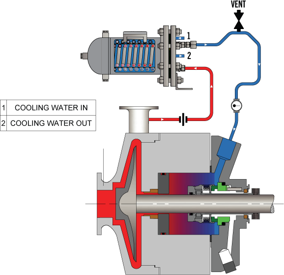
Recirculates process fluid from the seal chamber through a cooler, then back into the seal chamber using a pumping ring; By continually recirculating seal chamber fluid through the seal flush cooler, it provides greater cooling capacity compared to Plan 21
Recirculates process fluid from pump discharge through a cyclone separator, sending clean process fluid to the seal chamber and particulates back to pump suction; For optimum performance, particulates should have a specific gravity twice the process fluid
Delivers clean or cool flush fluid to the seal chamber from an external source; Employs a close-clearance throat bushing to ensure seal chamber higher pressure; Because flush fluid will migrate past the bushing it must be chemically compatible with process fluid
Recirculates process fluid from pump discharge through a cyclone separator, sending clean process fluid to the seal chamber and particulates back to pump suction; Particulates should have a specific gravity twice the process fluid
Each of these API seal flush plans has options to help tailor the plan to the requirements of the specific pumping process. Instrumentation such as temperature, pressure, and flow gauges help monitor system performance. If you’re not using process fluid to lubricate the mechanical seal, flush fluids can be water, water/glycol, or mineral- or synthetic-based hydraulic and lubricating oils. Cooling capacity needs to be carefully calculated based on process fluid temperature, pressure, and mechanical seal type. When you’re faced with choosing among these options, the guidance of an experienced, local seal support system vendor is critical. Well-informed design decisions are the foundation for long-term reliability.
Description: The majority of refinery processes deal with hydrocarbons. In comparison to process side API seal flush plans, between seal plans provide a higher degree of protection against leakage. As a result, between seal plans (or dual mechanical seals) are used in the majority of refinery pumping applications.
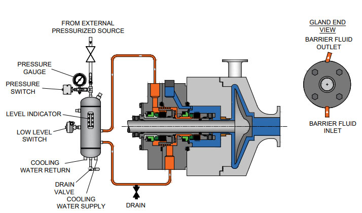
These API seal flush plans deliver a barrier (pressurized) or buffer (unpressurized) fluid delivered from an external source to the space between the inboard and outboard seals. Barrier fluids can be a water/glycol mix, or mineral- or synthetic-based hydraulic and lubricating oils.
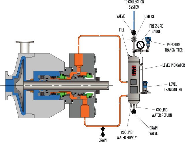
Uses a pressurized bladder accumulator to isolate pressurized gas from barrier fluid and delivers clean barrier fluid between the inboard and outboard seals at a pressure higher than the process fluid pressure; An internal pumping ring circulates the nitrogen barrier fluid; Bladder prohibits gas absorption into the barrier fluid and facilitates higher operating pressures than Plan 53A
Preferred for applications where the seal chamber pressure varies during pump operation; Uses a sensing line from the seal chamber into the piston accumulator to deliver barrier fluid from a reservoir at a constant, but higher pressure than the process fluid pressure; An internal pumping ring circulates the barrier fluid
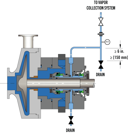
Delivers buffer gas (typically plant nitrogen) from an external source to the seal chamber at a lower pressure than the process pressure; Uses a coalescing filter to remove any moisture and particulate present in the plant nitrogen supply; Any process fluid vaporizing across the inboard seal is then swept into a closed collection system
Delivers barrier gas (typically plant nitrogen) from an external source to the seal chamber at a higher pressure than the process pressure; Uses a coalescing filter to remove any moisture and particulate present in the plant nitrogen supply; Allows a small amount of nitrogen to leak into the process fluid
These plans also can also have a significant number of design options. Plans 54 and 55 lend themselves to a high degree of customization regarding reservoir volume, pump, filters, coolers, and instrumentations. These plans can also be configured to support multiple pumps with similar pumping characteristics. Plan 72 has the option of adding a condensing or non-condensing leakage collection system. For each of these, determining the proper pressure is one of the most critical factors regarding system performance.
If you’re making an investment in a new or upgraded seal support system, it’s well worth the time to work with an experienced Field Engineer who understands the importance of configuring the options for the specific pumping process.
Description: In comparison to the range of options in the above API seal flush plan categories, atmospheric side plans are much simpler. Their purpose is to provide a non-pressurized cooling flush to a mechanical seal"s faces on the atmosphere side to prevent or remove solid formations—crystallization, icing, and coking. Water, steam, and nitrogen are the typical flush fluids.
A quench improves atmospheric seal performance by absorbing or removing any process fluid leakage, preventing process fluid from being exposed to the atmosphere, and cooling or heating (relative to the process fluid temperature) to prevent the formation of solids proximate to the mechanical seal.
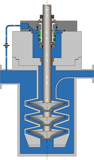
Delivers clean flush fluid from an external reservoir to the atmospheric side of a single seal preventing icing at ambient temperatures on the atmospheric side; Used for vertical pump applications
Delivers a low rate (2 to 4 PSI) of quench fluid (nitrogen, water, steam) from an external source to the atmosphere side of the seal. Typically uses a throttle bushing for containment.
Each of the atmospheric side plans has an option to collect condensing process fluid leakage into a reservoir. In the event of excessive leakage, a level transmitter on the reservoir triggers an alarm.
The proper design of your flush plan is the biggest factor in ensuring long-term performance and reliability. You may have the in-house expertise to determine the appropriate API flush plans for the various pumps in a new installation or upgrades of existing pumps, but your outcomes will improve if you engage the service of an experienced, local partner. In working with process engineers for over the years, I can tell you first-hand that you’ll:
An experienced API seal flush plan partner has Field Engineers to evaluate each process and pumping conditions, fluid compatibility issues, and infrastructure considerations (on-site or virtually) to help determine plan requirements.
Swagelok has decades of expertise in helping refineries determine the proper API seal flush plans. We can design, fabricate, and thoroughly test the API seal plans prior to delivery. For over 50 years, Swagelok has been meeting the seal support needs of refineries in Northern California. We offer a complete range of API seal flush plans, available as kits or assemblies.
To learn howSwagelok Northen Californiacan assist you in choosing API seal flush plans that are right for your process needs by providing expert consultation, design, and fabrication,contact our teamtoday by calling
After more than five years of planning, the American Petroleum Institute (API) is preparing to release the 4th edition of API Standard 682 (ISO 21049:2011). The API 682 standard, which dates back to 1994 and is formally known as Shaft Sealing Systems for Centrifugal and Rotary Pumps, offers specifications and best practices for mechanical seals and systems to pump end users.
The standard’s latest edition began to take shape in 2006, when API formed a 4th edition task force to respond to end users’ questions and comments about previous editions. The task force soon realized that major changes, including reorganization and editing, would be necessary. While addressing every aspect of the resulting 4th edition (which is more than 250 pages long) would be impossible, this article summarizes the standard’s main points.
Those who use API 682 should understand the standard’s scope and remember that the standard does not include specifications for equipment outside that scope, such as engineered seals or mixers. Another important but often misunderstood point is that API 682’s figures are illustrative and not normative in their entirety.
For example, one of API 682’s figures shows a fixed throttle bushing combined with a rotating Type A seal, but seal manufacturers do not always have to combine these two components. The standard provides normative details in clauses and tables to help purchasers distinguish between requirements and suggestions.
The 4th edition continues to divide seals into three categories, three types and three arrangements. For all practical purposes, seal manufacturers can combine a seal’s component parts into nearly any orientation or configuration. Each orientation and configuration has advantages and disadvantages with respect to certain applications, performance and system disturbances.
Before the 4th edition, API 682 did not specify a minimum clearance between the inside diameter of a stationary seal part and the outside diameter of a rotating seal part. The 4th edition specifies this minimum clearance—typically the clearance between the sleeve and the mating ring. The specified clearances are representative of standard clearances that end users have used for decades. End users should not consider seal components to be “shaft catchers” to restrict shaft movement. The minimum clearance specified in API 682 also applies only to equipment within the standard’s scope. Equipment outside that scope, such as non-cartridge seals, older pumps, non-API 610 pumps and certain severe services, might benefit from larger clearances.
The new standard also updates the default bushings for the gland plate for the three seal categories. Fixed throttle bushings are now the default for Category 1 only, while floating bushings are the default for Categories 2 and 3.
While the 4th edition features the recommended seal selection procedure from the standard’s first three editions, it adds an alternative selection method in Annex A. Proposed by task force member Michael Goodrich, this alternative method recommends using material data sheet information to select a sealing arrangement.
Plans 66A and 66B are new to the standard, although end users have used them previously in pipeline applications. These plans detect and restrict excessive leakage rates in case of an Arrangement 1 seal failure.
The 4th edition now requires Plan 52, 53A, 53B and 53C systems to have a sufficient working volume of buffer or barrier fluid for at least 28 days of operation without refilling. As a point of reference, the default reservoir for Plans 52 and 53A has a three-gallon capacity, or pot, for pump shafts smaller than 2.5 inches and a five-gallon pot for larger shaft sizes. Plan 53C must have the same working volume of fluid as Plan 53A. For Plan 53B, the default bladder and accumulator sizes are five gallons and nine gallons, respectively. The design of Plan 53B systems can be complex, especially when ambient temperatures vary widely, and purchasers should become familiar with the calculations and procedures in the 4th edition’s Annex F tutorial. The new edition also discusses the option of adding a pressure gauge and isolation valve to check the accumulator or bladder’s integrity in a Plan 53B system.
The 4th edition has revised the data sheets in Annex C extensively to make them the same for all seal categories. Only two data sheets are included in the 4th edition—one in metric units and one in U.S. customary units. The new edition also folds Annex J into Annex E.
Previous editions of API 682 required metal plugs and anaerobic sealants when shipping new or repaired cartridges. After much debate, the task force decided that threaded connection points should be protected with plastic plugs for shipment. These plastic plugs should be red and have center tabs that operators can pull easily to distinguish the plugs from metal plugs. Shippers should also attach yellow warning tags to the plugs to indicate that end users need to remove the plugs before operation.
Although tutorial notes are scattered throughout API 682, this edition expands the tutorial section, Annex F, from seven pages to 42 pages. The expanded annex includes illustrative calculations. In particular, users interested in systems such as Plan 53B will find Annex F to be useful.
The 4th edition of API 682 is the product of more than 20 years of discussion, debate, usage and peer review. It includes a strong set of defaults and is by far the best and most logical starting point for mechanical seal and systems use. Equipment operators should take the time to familiarize themselves with API 682 to get the most out of this comprehensive standard.
When discussing slurry pump seal support plans it seems that the terms “Flush” and “Quench” are often confused and or misused. With the concept being slightly different for mechanical seal boxes vs packed seal boxes I will separate these, discussing each in turn.
The basic mechanical seal flush plan is very simple. It calls for a clear/clean liquid, usually water, to be introduced into the space between the actual seal and an impeller side exit restriction. The flush liquid is introduced at a pressure above that of the pumpage, thus assuring a positive outward flow/flush and a clean operating environment for the mechanical seal. This is illustrated below.
The definition of a flush is a “fluid which is introduced into the seal chamber on the process fluid side in close proximity to the seal faces and typically used for cooling and lubricating the seal faces.
When flushing is required, Toyo recommends the use of an API plan 32 seal piping arrangement as it is better suited in services containing solids or contaminants which could damage the seal faces if recirculated in the flush media.
The Plan 32 typically uses a clear clean fluid supplied from an external source delivered to the primary seal faces on the process fluid side of the seal. With the use of a close-clearance throat bushing, the stuffing box can be back pressured to an elevated pressure ensuring the flushing fluid will not flash across the seal faces.
A quench plan, as the name indicates, is designed to quench or cool the seal. It is normally used if short periods of dry running are expected. As illustrated bellow, the fluid is introduced into the area between the back of the seal faces and the close fit exit on the drive side of the pump.
API 682 3rd Edition defines a quench as a“neutral fluid, usually water or steam, is introduced on the atmospheric side of the seal to retard formation of solids that may interfere with movement, or for other purposes.”
Some quench seal plans replace the close fit exit restriction with a secondary seal and a top exiting port that can be plumbed to capture the spent quench fluid and route it away from the rotating assembly. The principal is however just the same, we are trying to cool the seal not in any way flush the seal.
The primary goal of all flush water plans is to preclude the pumpage from contaminating the seals. As such flush water plans for packed boxes are very similar to that of mechanical seal boxes. However, as illustrated below there are some obvious mechanical differences. The most striking difference is the addition of a seal (packing) located between the injection port and the exit restriction. This minimizes the volume of flush liquid consumed.
From an operational standpoint, the packed box differs as it requires some leakage to assure lubrication and prevent heat build-up. The mechanical seal box should have no leakage.
With a standard flush plan, flow is typically adjusted by compressing the packing until a few drops are observed leaking out of the seal on the drive side. On a quench plan, flow rate is set by adjusting an inlet valve while at the same time using a valve on the exhaust side to maintain the correct seal box pressure. If the exit water from the seal box is too hot, flow rate is increased until exit water is cool while still maintaining the proper seal box pressure.
I hope this short blog helps clear up some of the confusion with seal flush plans. Before signing off for today, let me confirm the information provided today is general info only. Always refer to the pump manuals for specific details. If still in doubt, our applications team here at Toyo is always willing to support you in any way they can.
After nearly six years of intensive work, the American Petroleum Institute (API) 682 mechanical seal standard is soon to be adopted. Since its introduction in 1994, API 682 has become “the” standard that sets the global tone for the procurement and operation of seal and supply systems for centrifugal pumps in the oil and gas sector as well as in the petrochemical industry. API 682 is a “living” standard that directly incorporates diverse practical experience in its regular updates.
Founded in 1919 and located in Washington, D.C., the API includes close to 500 companies from the oil and gas sector and the petrochemical industry. Since 1924, it has focused on technical standards. To this day, API has adopted roughly 500 standards that address diverse processes and components in detail—which ultimately ensure a maximum of operating and process reliability. API standards, which are clearly defined and in part attached to approval tests, do not take effect only in the U.S. In many cases, they have developed into worldwide industrial standards. API is often considered a synonym for safety and reliability.
Individual standards—including API 682 regulations for mechanical seals and seal supply systems—have become so popular that they have even been referenced in outside industry applications. The authors of the new edition point out that this was never the intention and clarify the actual purpose of the API 682 standards. The standards are for seal systems in pumps—not in agitators or compressors—and for oil and gas and petro chemistry—not for water supply or the food sector.
Initial information about mechanical seals was originally provided in the API 610 pump standard. During the 1990s, API 682 developed into a separate, more comprehensive standard for mechanical seals and supply systems. The API 682 standard is continually maintained and updated by end users and manufacturers. Another quality of API 682 is that it does not typically permit only a single technical solution. In addition to proven and tested standard solutions (defaults), the regulations also deliberately list alternatives (options) and even allow customized solutions (engineered solutions). This diversity is demonstrated more clearly in this edition than in previous ones.
The composition of the 25-member task force is representative of the practical way in which API approaches the topic of seals. Since 2006, the task force has been updating the 3rd Edition of API 682 that took effect in 2004 and is still valid. In addition to leading seal system manufacturers, the American-European expert panel—which intentionally counted on non-API member collaboration—also included renowned planning companies and representatives from some of the largest mineral oil groups, who are users of seal solutions.
While the currently valid API 682 edition included approximately 200 pages, the 4th Edition is 260 pages. The revised edition is organized into a body of text with 11 chapters and detailed annexes with a significantly expanded scope. For example, Annex I provides detailed information on more than 20 pages for API-conform seal qualification tests.
Default seals and options must be tested using five different media and clearly defined operating conditions representative of typical API applications. Together with the described seal designs, this yields a high number of possible test variations. In the process, the expended time per test and seal type can take up to 200 hours. The result for typical industry seal designs is documented in a test certificate and a detailed report. Customer-specific qualification tests can be agreed upon for engineered seals.
Essentially, checked and tested product safety is the core of the standard. The objective of API 682 is continuous operation of at least three years (25,000 operating hours subject to the legally stipulated emission values, or for maximum “screening value” of 1,000 parts per million by volume, EPA Method 21), increased operational reliability and simplified maintenance. The standards defined by API apply exclusively to cartridge systems with a shaft diameter of 20 to 110 millimeters and a defined range of operating conditions.
The 4th Edition also includes the revised product coding system (Annex D). The proven classification parameters “Category,” “Arrangement” and “Type” will be continued. They are listed first in the revised code and provide information about the setup and field of use of the respective API seal. The seal arrangement includes:Arrangement 1—single seals are differentiated
Details regarding the supply system—specified as “Plan”—are in the old and new code. The addition of precise information regarding material selection and shaft diameter is new. This gives more meaning to the code and guarantees a clear specification of the mechanical seal and its operation—from selection to documentation. Industry experts agreed that the expanded coding system will prove itself in practice and endure permanently.
The selection process of an API seal system is complicated. Several flow charts and tables on more than 10 pages are dedicated to this topic in the new edition. To provide more precision in the technical selection process when determining the arrangement, an alternative selection tool (Annex A.4) has been included in the 4th Edition for the first time. This method is based on the established “Risk & Hazard Code” and has been tested in practice.
The starting point is the pumped medium. Its real hazard potential is accurately recorded and described by the “Hazard & Risk Code” in the “Material Safety Data Sheets.” Decisions can be made quickly and securely, for example, about whether a single seal (Arrangement 1) will suffice, or if a double seal with barrier pressure system is required.
The experience-based, “lived” standard of the API 682 edition is demonstrated by the two silicon carbide (SiC) variants, reaction-bonded silicon carbide and self-sintered silicon carbide, which are treated equally as default materials for sliding surfaces in chemical (Category 1) as well as in refinery/oil and gas applications (Category 2 or 3). Until now, sintered SiC was set for chemical applications because of its superior chemical stability, whereas the reaction-bonded variant established itself in the refinery sector. This restrictive allocation was canceled because of practical application examples (best practices) that were brought to the attention of the task force, which called for a course correction.
Plan 53 with a pressurized barrier fluid belongs to the more complicated supply systems. In detail, three types are possible:Plan 53A is the solution with the constructively least amount of effort. The pressure on the barrier medium is generated directly via gas pressurization—normally with nitrogen—in the tank. However, the application has limits, since higher barrier pressures could cause a dissolution of the nitrogen in the barrier medium. The consequence would be the risk of inadequate lubrication in the sealing gap of the mechanical seal. That is why Plans 53B and 53C are used for higher barrier pressure.
A new prescribed refilling interval of at least 28 days has also been included in the 4th Edition of API 682. The fluid reservoir must be large enough to supply the seal with barrier fluid for this entire period—without refilling. To obtain the most compact reservoirs, the seal manufacturers are required to find optimized system solutions with minimal leakage values for the barrier medium.
Also, Plans 03, 55, 65A, 65B, 66A, 66B and 99 have been newly included in the regulations and, along with the already existing plans, are described in detail in Annex G.
The transition to transmitters as default is illustrative: the API specifications primarily concern operating and process reliability and only then consider economic viability. This universal application is also verified by the decision of the task force to permit only seamless pipes in the future for “Piping” for the supply systems. The use of welded pipes, which would be less expensive, was considered unacceptable.
The task force also addressed the topic of heat resistance of the instrumentation used in supply systems pragmatically. In the past, frequent debates occurred regarding whether supply systems for high-temperature applications—for example, a 400 C approved pump—have to be equipped with special instrumentation for high temperatures. Now the temperature specification for the instrumentation has been limited to 100 C. If instruments with higher temperature limits are required in the future, the customer has to inform the seal vendor accordingly.
The essential improvements, in addition to the technical supplements and updates, are the clear structures of the latest API regulation. The body of the text was tightened and structured appropriately, whereas technical details and background information were placed in the annexes. Some of the wording in individual chapters was revised to improve understanding.
The improved user friendliness is shown in Annex E, which addresses structured communication and data exchange between suppliers and customers. Descriptions that previously encompassed many pages in API 682 are now bundled into two compact checklists in the 4th Edition. The first list systematically describes what must be considered for inquiries and quotations. It specifies the data that needs to be provided and the additional information and documents with which it must be combined. For example, seal systems that deviate from standardized API solutions must be shown separately. Annex E is completed by a second checklist that shows in which order the documentation is necessary.
Apart from the numerous technical updates and improved user friendliness, one detail is visually the most striking innovation of this edition: all mechanical seals are equipped with red plugs in the supply connections of the seal gland upon delivery. Until the unit is installed, these plastic closures prevent the ingress of dirt in the seal. During operation, the connections are either assigned to pipelines, or the plastic plugs are replaced with enclosed metal plugs. An additional benefit is that the 4th Edition API seals are quickly identified by the red plugs. Editor’s Note: This article was previously published in Upstream Pumping Solutions, July/August 2013.

FLUSH PLANS FOR MECHANICAL SEALS – INTRODUCTIONPumps and seals are being installed into increasingly difficult services. Forsuccessful operation of mechanical seals, the environment and care of the sealsrequire more sophisticated seal chambers and flushing arrangements. This sectionof the Dean Pump Price Book is designed to allow the application and pricing offlush plans suitable to meet the requirements for the mechanical seal.The American Petroleum Institute (API) has defined certain seal flusharrangements known by their plan numbers. Later, the flush plans developed forthe ANSI standard followed suit and placed the digits "73" in front of the API plannumber to achieve some standardization within the process industry. Thus, APIplan 11 becomes and ANSI Plan 7311.Dean Pump has worked with many engineering houses and customers over theyears and has developed a great deal of experience with sealing systems. WhileDean will quote any flush system requirement as requested by a particularcustomer, it has been found that the API/ANSI systems generally meet or exceedmost customer requirements. In addition, Dean Pump developed the Seal GuardEnvironment systems that provide the ultimate mechanical seal flush plan. Forsystems that do not require ANSI/API flush plans, Dean Pump has also includedthe P1200 loop, which is a basic low cost flush plan to satisfy the economyminded customer.The experience of Dean Pump is contained in these price pages. Many of theflush plans are divided into "Toxic/Flammable" and "Non-Toxic/Non-Flammable“services. The information on these plans along with the details described in the"Special Notes" section can be used as a guide in quoting and discussing optionswith customers. The "fine print" in the Special Notes section provides a multitude ofdetails about each flush system. For example, a customer requesting all socketwelded connections can not have every connection welded. Some accommodationmust be made for disconnecting the system. Being aware of the requirements ofthe customer and the manufacturing limitations of the product is extremely helpful.API flush plans are based on the 7 th Edition of API610. Newer versions of the APIspecifications has limited the cooling and flushing options available.Finally, if there are any doubts, questions, or comments, please feel free to call theFactory and the seal vendor.Effective: FEBRUARY 2011 • Replaces: NEWPage 1
SEAL GUARD SYSTEMS – PRODUCT DESCRIPTIONSeal Guard systems are designed to provide a clean liquid for seal flushing thatprovides protection for the mechanical seal in the pump seal chamber. Dean Pumpoffers two basic systems to guard against mechanical seal failure. These systemswill also help to prolong the life of the seal. Both systems are filtration systemsinstalled into the seal flush lines to remove stray abrasive particles which causeseal face wear.Seal Guard A - is designed for filtration only. Particles larger than 10 microns arefiltered from the system using clean-able or replaceable 316SS woven filterelements.Seal Guard B - is designed for high temperature applications and includes a heatexchanger installed ahead of the replaceable filter elements for both filtration andtemperature control.Seal Guard systems are most often used with MIN-FLO Bushings in the pump sealchamber. These bushings restrict the flow from the seal chamber back into thepump during operation and increases the effectiveness of the Seal Guard system.Seal Guards can be used on any pump product line. Their sale is not limited toDean Pump products. Seal Guards are hydrostatically tested but do not meet anyindustrial standard and are not for application to API610 series pumps. Seal Guardapplications must be limited to iron or steel pumps and are not suitable forapplications that require alloy materials.The Seal Guard system is fully described in Bulletin A2000.Effective: FEBRUARY 2011 • Replaces: NEWPage 2
SEAL GUARD SYSTEMS – (See Note #1)Model A Series – Filtration Only (See Note #2)Mounted on Pump BaseplateModel Description List PriceA500T A Series Seal Guard - Filtration - Threaded Connections $4,483A500F A Series Seal Guard - Filtration - Flanged Connections C/FA700T A Series Seal Guard - Filtration - Threaded Connections C/FBD500TB500TModel B Series – Filtration and Cooling (See Notes #2 & #3)Mounted on Separate BaseplateModel Description List PriceBD200T B Series Seal Guard - Cooling & Filtration - $5,248Threaded Connections & Duplex FilterB400T B Series Seal Guard - Cooling & Filtration - $5,248Threaded Connections & Simplex FilterB400F B Series Seal Guard - Cooling & Filtration - C/FFlanged Connections & Simplex FilterB500T B Series Seal Guard - Cooling & Filtration - $6,226Threaded Connections & Simplex FilterBD500T B Series Seal Guard - Cooling & Filtration - $8,240Threaded Connections & Duplex FilterNotes:1. Seal Guard systems are not rated for API application and are suitable for pumps in steel or iron construction only. Do notuse for 316SS or other alloy applications.2. The product description letters and numbers are as follows:First Letter - Seal Guard Series A - Filtration Only; B - Cooling and Filtration. (The letter D following in the second positionindicates a Duplex arrangement.); 3 Digit Number indicates the pressure rating of the Seal Guard system in psi.;Final Letter: T - Threaded Construction; F - Flanged Construction3. The heat exchangers provided for Seal Guard B are furnished with a steel shell and 316SS tube as standard.Effective: FEBRUARY 2011 • Replaces: NEWPage 3
DEAN P1200 ECONOMY FLUSH PLAN FOR PROCESS PUMPSPlan Description:Dean Plan P1200 systems include piping (or tubing) from the pumpdischarge gauge connection to the seal flush connection on the pumpbackhead or seal gland. These plans include all piping and/or tubing.List Prices (Notes 1 & 3)Carbon SteelCarbon SteelFitted 316SS Pipe 316SS PipeSystem Description (Note #2) Tubing Threaded ThreadedRecirculation of Pumpage from Pump Case toP1200 Seal Without Orifice (Similar to API Plan 11 orANSI Plan 7311) VALVE NOT INCLUDED$216 $329 $456 $692Valve Valve for Recirculation Line $205 $762 $205 $762General Notes:1. For all other flush plans, refer to API/ANSI Flush Plans shown elsewhere for your particular requirements.2. The plan with carbon steel tubing uses carbon steel fittings with 316SS tubing.3. Connections on the casing require a price adder for discharge gauge connections and may require an additional price adderif the seal chamber requires back drilling.Effective: FEBRUARY 2011 • Replaces: NEWPage 4
SOME COMMENTS AND RECOMMENDATIONSABOUT API/ANSI FLUSH PLANSThere are two organizations in the United States which have taken the lead in developingacceptable standards for the pump industry. The American Petroleum Institute (API) and AmericanNational Standards Institute (ANSI) have outlined a number of flush plans which encompass themajority of applications. API610 is mainly recognized as a standard which defines the qualityrequirements of a pump and/or system. ANSI-B73.1 is viewed as more of a dimensional and featurestandard. ANSI plans are designated the same as API plans except for the addition of a "73" prefixon the plan number. For example, an API Plan 21 is designated as an ANSI Plan 7321.API and ANSI flush plans are similar and upon initial examination look nearly identical. However,there are definite differences in their construction. Often, API flush plans, which are historicallylocated in refinery environments, are piped and welded. ANSI plans, on the other hand, can utilizetubing. Another notable difference is in the API plan 52/53 and the ANSI plan 7352/7353. APIspecifies Schedule 40 minimum thickness vessels. ANSI allows for the use Schedule 10 vessels. Allof the plans are offered in steel and stainless steel construction. They also have differingconstructions for Toxic/Flammable or Nontoxic/Nonflammable applications.Meeting the customer"s specific requirements is the most important consideration in applying theseplans. Many customers modify their individual requirements from the API and ANSI specifications.Sometimes these are more stringent rules than the API and ANSI specifications. These must takeprecedence over the standard flush plans. There are some limitations as to what the flush plans canor cannot accomplish. The Special Application Notes section on each sheet identifies the particularlimitations of each of the flush plans. For example, a flush loop which requires socket welded jointscan not have all the connections welded some provision must be made to allow for disassembly andrepair.When applying a particular flush plan to a specific job, great care should be taken to insure theneeds of the customer are met. Do not select a plan based solely upon pricing. In general, most APIplans require piping and many require welded joints. Note that these are the most expensive plans.A few API services permit the less expensive plans but, the customer"s requirements takeprecedence. ANSI, on the other hand, is much less specific but still requires close analysis of thecustomer"s specifications and requirements for guidance. However, API plans are often seen onANSI type pumps. Oil companies are very likely to request the more expensive plan and will pay forit. Do not make errors in this area. If there is any doubt, or questions regarding plan selection, sendthe specification/ requirements to the factory for review. The factory will provide any comments,limitations, and pricing that is required.Effective: FEBRUARY 2011 • Replaces: NEWPage 5
API PLAN 11 - FLUSH PLAN FOR PROCESS PUMPS (Note #1)ANSI PLAN 7311 – FLUSH PLAN FOR CHEMICAL PUMPSPlan Description:API Plan 11 (ANSI Plan 7311) systems include piping (ortubing) from the pump discharge gauge connection throughan orifice to the seal flush connection on the pumpbackhead or seal gland. These plans include all piping,tubing, and the orifice. Refer to Note #B for additionalpump drilling.SYSTEMS FOR NON-TOXIC AND NON-FLAMMABLE APPLICATIONSSystem DescriptionDescription Special Notes Max. Press. Max. Temp. List PriceAASteel Threaded Pipe and Fittings with 316SS Tubingand Tube Connectors2, 3, 7, 19 500psi 800º F. $ 413AB Steel Threaded Pipe and Fittings 2, 5, 8 500psi 800º F. $ 627AC316SS Threaded Pipe and Fittings with 316SS Tubing andTube Connectors2, 3, 7, 19 500psi 850º F. $ 483AD All 316SS Threaded Pipe and Fittings 2, 5, 8, 500psi 850º F. $1,496SYSTEMS FOR TOXIC AND/OR FLAMMABLE APPLICATIONSSystem Description Special Notes Max. Press. Max. Temp. List PriceAESocket Welded Steel Pipe and Fittings with 316SS Tubingand Tube Connectors1, 4, 7, 19 500psi 300º F. $ 890AF Socket Welded Steel Pipe and Fittings 1, 6, 8 500psi 800º F. $1,124AGSocket Welded 316SS Pipe and Fittings with 316SS Tubingand Tube Connectors2, 3, 7, 19 500psi 300º F. $ 982AH All Socket Welded 316SS Pipe and Pipe Fittings 2, 5, 8 500psi 850º F. $1,577General Notes:A. ALL PUMPS - The plans are similar to but may not comply with API610, 5 th Ed. Review customer requirements as plansmay not comply with later editions or specific customer requirements.B. ALL PUMPS - Flush plans require one or more pump taps. Add the price of the discharge and suction gauge connections ifrequired. For clamped seat applications, consult factory.Special Application Notes:1. Pipe connections at the pump are threaded and are not backwelded.2. All pipe joints are threaded.3. Pipe nipples, threaded pipe fittings, stainless steel tubing, and compression type stainless steel tube connectors.4. Pipe, pipe nipples, socket weld pipe fittings, backwelded threaded pipe fittings, stainless steel tubing and compression typestainless steel tube connectors with threaded pipe connections that are not backwelded.5. Pipe nipples, threaded pipe fittings, and threaded pipe unions.6. Pipe, pipe nipples, socket weld pipe fittings, backwelded threaded pipe fittings, socket weld pipe unions.Effective: FEBRUARY 2011 • Replaces: NEWPage 7
API PLAN 12 - FLUSH PLAN FOR PROCESS PUMPS (General Note #A)ANSI PLAN 7312 – FLUSH PLAN FOR CHEMICAL PUMPSPlan Description:API Plan 12 (ANSI Plan 7312) systems include piping (ortubing) from the pump discharge gauge connection througha Y-strainer, and orifice to the seal flush connection on thepump backhead or seal gland. These plans include allpiping, tubing, and the orifice. Refer to Note #B foradditional pump drilling.SYSTEMS FOR NON-TOXIC AND NON-FLAMMABLE APPLICATIONSSystem DescriptionDescription Special Notes Max. Press. Max. Temp. List PriceBASteel Threaded Pipe and Fittings with 316SS Tubing andTube Connectors and Y-Strainer2, 3, 7, 9, 19 500psi 800º F. $ 638BB Steel Threaded Pipe and Fittings 2, 5, 8, 9 500psi 800º F. $1,123BC316SS Threaded Pipe and Fittings with 316SS Tubing andTube Connectors and Y-Strainer2, 3, 7, 9, 19 500psi 850º F. $ 939BD All 316SS Threaded Pipe and Fittings and Y-Strainer 2, 5, 8, 9 500psi 850º F. $1,736SYSTEMS FOR TOXIC AND/OR FLAMMABLE APPLICATIONSSystem Description Special Notes Max. Press. Max. Temp. List PriceBESocket Welded Steel Pipe and Fittings with 316SS Tubingand Tube Connectors and Y-Strainer1, 4, 7, 10, 19 500psi 300º F. $1,298BF Socket Welded Steel Pipe and Fittings and Y-Strainer 1, 6, 8, 10 500psi 800º F. $1,602BGSocket Welded 316SS Pipe and Fittings with 316SS Tubingand Tube Connectors and Y-Strainer2, 3, 7, 9, 19 500psi 300º F. $1,270BHAll Socket Welded 316SS Pipe and Pipe Fittings andY-Strainer2, 5, 8, 9 500psi 850º F. $1,817General Notes:A. ALL PUMPS - The plans are similar to but may not comply with API610, 5 th Ed. Review customer requirements as plansmay not comply with later editions or specific customer requirements.B. ALL PUMPS - Flush plans require one or more pump taps. Add the price of the discharge and suction gauge connections ifrequired. For clamped seat applications, consult factory.Special Application Notes:1. Pipe connections at the pump are threaded and are not backwelded.2. All pipe joints are threaded.3. Pipe nipples, threaded pipe fittings, stainless steel tubing, and compression type stainless steel tube connectors.4. Pipe, pipe nipples, socket weld pipe fittings, backwelded threaded pipe fittings, stainless steel tubing and compression type stainless steeltube connectors with threaded pipe connections that are not backwelded.5. Pipe nipples, threaded pipe fittings, and threaded pipe unions.6. Pipe, pipe nipples, socket weld pipe fittings, backwelded threaded pipe fittings, socket weld pipe unions.7. Stainless steel orifice plate in tube connector.8. Stainless steel orifice plate in pipe union.9. Y-strainer has stainless steel screen and 1/4" NPT (plugged) blow-off connection.10. Y-strainer has stainless steel screen and bolted cap without blow-off connection.19. This loop has stainless steel tubing and should not be used where chlorides are present.Effective: FEBRUARY 2011 • Replaces: NEWPage 8
API PLAN 21 - FLUSH PLAN FOR PROCESS PUMPS (General Note #A)ANSI PLAN 7321 – FLUSH PLAN FOR CHEMICAL PUMPSWHEN SPECIFIEDPlan Description:API Plan 21 (ANSI Plan 7321) systems include piping (ortubing) from the pump discharge gauge connection throughthe heat exchanger to the seal flush connection on thepump backhead or seal gland. These plans include allpiping, tubing, heat exchanger, and the orifice. The heatexchanger includes a steel shell and 316SS tubing. Ref.Note #B.SYSTEMS FOR NON-TOXIC AND NON-FLAMMABLE APPLICATIONSMAWP 500psi @System Description Special Notes 300º F 650º F 750º FCACBCCCDSteel Threaded Pipe and Fittings with 316SS Tubing andSteel Threaded Pipe and Fittings and Heat Exchanger316SS Threaded Pipe and Fittings with 316SS Tubing andAll 316SS Threaded Pipe and Fittings and Heat Exchanger2, 3, 7, 11, 13,2, 5, 8, 11, 13,2, 3, 7, 11, 13,2, 5, 8, 11, 13,Heat Exchanger (Steel Sheel & 316SS Tubing)(Steel Sheel & 316SS Tubing)Heat Exchanger (Steel Sheel & 316SS Tubing)(Steel Sheel & 316SS Tubing)19, 212119, 2121$3,301$3,663$5,016$5,229$3,301$3,663.$5,489$5,701$4,864$5,227$6,700$6,913ADD Temperature Indicator 13 C/F C/F C/FSYSTEMS FOR TOXIC AND/OR FLAMMABLE APPLICATIONSSystem Description Special Notes 300º FMAWP 500psi @650º F 750º FCESocket Welded Steel Pipe and Fittings and Heat Exchanger 1, 6, 8, 11, 12,(Steel Sheel & 316SS Tubing) 14, 21$4,286 $4,286 $5,849CFAll 316SS 316SS Pipe and Fittings and Heat Exchanger 2, 5, 8, 11, 13, C/F C/F C/F(Steel Sheel & 316SS Tubing) 21ADD Temperature Indicator with Thermowell 14 C/F C/F C/FGeneral Notes:A. ALL PUMPS - The plans are similar to but may not comply with API610, 5 th Ed. Review customer requirements as plans may not comply withlater editions or specific customer requirements.B. ALL PUMPS - Flush plans require one or more pump taps. Add the price of the discharge and suction gauge connections if required. Forclamped seat applications, consult factory.Special Application Notes:1. Pipe connections at the pump are threaded and are not backwelded.2. All pipe joints are threaded.3. Pipe nipples, threaded pipe fittings, stainless steel tubing, and compression type stainless steel tube connectors.4. Pipe, pipe nipples, socket weld pipe fittings, backwelded threaded pipe fittings, stainless steel tubing and compression type stainless steeltube connectors with threaded pipe connections that are not backwelded.5. Pipe nipples, threaded pipe fittings, and threaded pipe unions.6. Pipe, pipe nipples, socket weld pipe fittings, backwelded threaded pipe fittings, socket weld pipe unions.7. Stainless steel orifice plate in tube connector.8. Stainless steel orifice plate in pipe union.11. Heat exchanger has 1/4" diameter, 18 gauge, stainless steel tubes good for the maximum operating temperature and pressure of the pump.12. Heat exchanger connections are threaded and are not backwelded to allow replacement of the tube coil.13. Dial thermometer is 3" diameter, bi-metal, and screwed into pipe TEE and is furnished only when specified.14. Dial thermometer is 3" diameter, bi-metal, and screwed into a thermometer socket which is welded into pipe TEE and is furnished onlywhen specified.19. This loop has stainless steel tubing and should not be used where chlorides are present.Effective: FEBRUARY 2011 • Replaces: NEWPage 9
API PLAN 22 - FLUSH PLAN FOR PROCESS PUMPS (General Note #A)ANSI PLAN 7322 – FLUSH PLAN FOR CHEMICAL PUMPSWHEN SPECIFIEDPlan Description:API Plan 22 (ANSI Plan 7322) systems include piping (ortubing) from the pump discharge gauge connection througha Y-strainer, through the heat exchanger to the seal flushconnection on the pump backhead or seal gland. Theseplans include all piping, tubing, heat exchanger, and theorifice. The heat exchanger includes a steel shell and316SS tubing. Ref. Note #19.SYSTEMS FOR NON-TOXIC AND NON-FLAMMABLE APPLICATIONSMAWP 500psi @System Description Special Notes 300º F 650º F 750º FDADBDCDDSteel Threaded Pipe and Fittings with 316SS Tubing andSteel Threaded Pipe and Fittings and Heat Exchanger316SS Threaded Pipe and Fittings with 316SS Tubing andAll 316SS Threaded Pipe and Fittings and Heat Exchanger2, 3, 7, 9, 11, 13,2, 5, 8, 9, 11, 13,2, 3, 7, 9, 11, 13,2, 5, 8, 9, 11, 13,Heat Exchanger (Steel Sheel & 316SS Tubing) and Y-Strainer(Steel Sheel & 316SS Tubing) and Y-StrainerHeat Exchanger (Steel Sheel & 316SS Tubing) and Y-Strainer(Steel Sheel & 316SS Tubing) and Y-Strainer19, 212119, 2121$3,549$3,912$5,454$5,460$3,549$3,912$5,928$5,955$5,112$5,475$7,138$7,145ADD Temperature Indicator with Thermowell 14 C/F C/F C/FSYSTEMS FOR TOXIC AND/OR FLAMMABLE APPLICATIONSMAWP 500psi @System Description Special Notes 300º F 650º F 750º FDEDFSocket Welded Steel Pipe and Fittings and Heat ExchangerAll 316SS 316SS Pipe and Fittings and Heat Exchanger1, 6, 8, 10, 11,2, 5, 8, 9, 11, 13,(Steel Sheel & 316SS Tubing) and Y-Strainer(Steel Sheel & 316SS Tubing) and Y-Strainer12, 14, 2121$4,534C/F$4,534C/F$6,097C/FADD Temperature Indicator with Thermowell 14 C/F C/F C/FGeneral Notes:A. ALL PUMPS - The plans are similar to but may not comply with API610, 5 th Ed. Review customer requirements as plans may not comply withlater editions or specific customer requirements.B. ALL PUMPS - Flush plans require one or more pump taps. Add the price of the discharge and suction gauge connections if required. Forclamped seat applications, consult factory.Special Application Notes:1. Pipe connections at the pump are threaded and are not backwelded.2. All pipe joints are threaded.3. Pipe nipples, threaded pipe fittings, stainless steel tubing, and compression type stainless steel tube connectors.4. Pipe, pipe nipples, socket weld pipe fittings, backwelded threaded pipe fittings, stainless steel tubing and compression type stainless steeltube connectors with threaded pipe connections that are not backwelded.5. Pipe nipples, threaded pipe fittings, and threaded pipe unions.6. Pipe, pipe nipples, socket weld pipe fittings, backwelded threaded pipe fittings, socket weld pipe unions.7. Stainless steel orifice plate in tube connector.8. Stainless steel orifice plate in pipe union.9. Y-strainer has stainless steel screen and 1/4" NPT (plugged) blow-off connection.10. Y-strainer has stainless steel screen and bolted cap without blow-off connection.11. Heat exchanger has 1/4" diameter, 18 gauge, stainless steel tubes good for the maximum operating temperature and pressure of the pump.12. Heat exchanger connections are threaded and are not backwelded to allow replacement of the tube coil.13. Dial thermometer is 3" diameter, bi-metal, and screwed into pipe TEE and is furnished only when specified.14. Dial thermometer is 3" diameter, bi-metal, and screwed into a thermometer socket which is welded into pipe TEE and is furnished onlywhen specified.19. This loop has stainless steel tubing and should not be used where chlorides are present.21. Heat exchanger size may vary from standard offering due to service conditions of liquid being pumped.Effective: FEBRUARY 2011 • Replaces: NEWPage 10
API PLAN 23 - FLUSH PLAN FOR PROCESS PUMPS (General Note #A)ANSI PLAN 7323 – FLUSH PLAN FOR CHEMICAL PUMPSWHEN SPECIFIEDPlan Description:API Plan 23 (ANSI Plan 7323) systems include piping (ortubing) from the seal flush connection on the backhead orseal gland, through the heat exchanger, and back to theseal gland. These plans include all piping, tubing, heatexchanger, and the orifice. The heat exchanger includes asteel shell and 316SS tuning. Ref. Note #B. – Similar toPlan 21 (7321) with addition of Pumping Ring in sealchamber and may require additional pump changes.SYSTEMS FOR NON-TOXIC AND NON-FLAMMABLE APPLICATIONSMAWP 500psi @System Description Special Notes 300º F 650º F 750º FEASteel Threaded Pipe and Fittings with 316SS Tubing and 2, 3, 11, 13, 19,Heat Exchanger (Steel Sheel & 316SS Tubing) and Y-Strainer 21C/F C/F C/FEBSteel Threaded Pipe and Fittings and Heat Exchanger(Steel Sheel & 316SS Tubing) and Y-Strainer2, 5, 11, 13, 21 C/F C/F C/FEC316SS Threaded Pipe and Fittings with 316SS Tubing and 2, 3, 11, 13, 19,Heat Exchanger (Steel Sheel & 316SS Tubing) and Y-Strainer 21C/F C/F C/FEDAll 316SS Threaded Pipe and Fittings and Heat Exchanger(Steel Sheel & 316SS Tubing) and Y-Strainer2, 5, 11, 13, 21 C/F C/F C/FADD Temperature Indicator 13 C/F C/F C/FSYSTEMS FOR TOXIC AND/OR FLAMMABLE APPLICATIONSMAWP 500psi @System Description Special Notes 300º F 650º F 750º FSocket Welded Steel Pipe and Fittings and Heat Exchanger 1, 6, 11, 12, 14,EEC/F C/F C/F(Steel Sheel & 316SS Tubing) and Y-Strainer 21All 316SS 316SS Pipe and Fittings and Heat ExchangerC/FEF2, 5, 11, 13, 21 C/FC/F(Steel Sheel & 316SS Tubing) and Y-StrainerADD Temperature Indicator with Thermowell 14 C/F C/F C/FGeneral Notes:A. ALL PUMPS - The plans are similar to but may not comply with API610, 5 th Ed. Review customer requirements as plans may not comply withlater editions or specific customer requirements.B. ALL PUMPS - Flush plans require one or more pump taps. Add the price of the discharge and suction gauge connections if required. Forclamped seat applications, consult factory.Special Application Notes:1. Pipe connections at the pump are threaded and are not backwelded.2. All pipe joints are threaded.3. Pipe nipples, threaded pipe fittings, stainless steel tubing, and compression type stainless steel tube connectors.5. Pipe nipples, threaded pipe fittings, and threaded pipe unions.6. Pipe, pipe nipples, socket weld pipe fittings, backwelded threaded pipe fittings, socket weld pipe unions.11. Heat exchanger has 1/4" diameter, 18 gauge, stainless steel tubes good for the maximum operating temperature and pressure of the pump.13. Dial thermometer is 3" diameter, bi-metal, and screwed into pipe TEE and is furnished only when specified.14. Dial thermometer is 3" diameter, bi-metal, and screwed into a thermometer socket which is welded into pipe TEE and is furnished onlywhen specified.19. This loop has stainless steel tubing and should not be used where chlorides are present.21. Heat exchanger size may vary from standard offering due to service conditions of liquid being pumped.All Requests for Plan 23/73223 Must Be Made to the Application EngineersEffective: FEBRUARY 2011 • Replaces: NEWPage 11
API PLAN 31 - FLUSH PLAN FOR PROCESS PUMPS (Note #1)ANSI PLAN 7331 – FLUSH PLAN FOR CHEMICAL PUMPSPlan Description:API Plan 31 (ANSI Plan 7331) systems include piping (ortubing) from the pump discharge gauge connection througha cyclone separator to the seal flush connection on thepump backhead or seal gland and fluid with solids back topump suction gauge connection. These plans include allpiping, tubing, and the cyclone separator. Refer to Note #Band #C for preparation. See note #D for performance.SYSTEMS FOR NON-TOXIC AND NON-FLAMMABLE APPLICATIONSSystem DescriptionDescription Special Notes Max. Press. Max. Temp. List PriceFASteel Threaded Pipe and Fittings with 316SS Tubing andTube Connectors2, 3, 7, 19 500psi 800º F. C/FFB Steel Threaded Pipe and Fittings 2, 5, 8 500psi 800º F. C/FFC316SS Threaded Pipe and Fittings with 316SS Tubing andTube Connectors2, 3, 7, 19 500psi 850º F. C/FFD All 316SS Threaded Pipe and Fittings 2, 5, 8, 500psi 850º F. C/FSYSTEMS FOR TOXIC AND/OR FLAMMABLE APPLICATIONSSystem Description Special Notes Max. Press. Max. Temp. List PriceFESocket Welded Steel Pipe and Fittings with 316SS Tubingand Tube Connectors1, 4, 7, 19 500psi 300º F. C/FFF Socket Welded Steel Pipe and Fittings 1, 6, 8 500psi 800º F. C/FFGSocket Welded 316SS Pipe and Fittings with 316SS Tubingand Tube Connectors2, 3, 7, 19 500psi 300º F. C/FFH All Socket Welded 316SS Pipe and Pipe Fittings 2, 5, 8 500psi 850º F. $4,518General Notes:A. ALL PUMPS - The plans are similar to but may not comply with API610, 5 th Ed. Review customer requirements as plansmay not comply with later editions or specific customer requirements.B. All items contain steel or stainless steel tubing and should not be used where chlorides are present. Consult factory forspecial pricing.C. ALL PUMPS - Flush plans require one or more pump taps. Add the price of the discharge and suction gauge connectionsif required.For clamped seat applications, consult factory.D. This plan may cause flow disruption in the suction and will decrease total head and efficiency and increase NPSHR.Special Application Notes:1. Pipe connections at the pump are threaded and are not backwelded.2. All pipe joints are threaded.3. Pipe nipples, threaded pipe fittings, stainless steel tubing, and compression type stainless steel tube connectors.4. Pipe, pipe nipples, socket weld pipe fittings, backwelded threaded pipe fittings, stainless steel tubing and compression typestainless steel tube connectors with threaded pipe connections that are not backwelded.5. Pipe nipples, threaded pipe fittings, and threaded pipe unions.6. Pipe, pipe nipples, socket weld pipe fittings, backwelded threaded pipe fittings, socket weld pipe unions.Effective: FEBRUARY 2011 • Replaces: NEWPage 12
API PLAN 32 - FLUSH PLAN FOR PROCESS PUMPS (Note #1)ANSI PLAN 7332 – FLUSH PLAN FOR CHEMICAL PUMPSPlan Description:API Plan 32 (ANSI Plan 7332) systems provide injection tothe seal from an external clean source provided by thecustomer. These plans include all piping, tubing, Y-strainer,pressure gauge, temperature indicator, and flow regulatingvalve. Refer to Note #A and #B for preparation.SYSTEMS FOR NON-TOXIC AND NON-FLAMMABLE APPLICATIONSSystem Description Special Notes Max. Press. Max. Temp. List PriceGAGBGCGDSteel Threaded Pipe and Fittings with 316SS Tubing and TubeConnectors with Y-Strainer, Pressure Gauge, Temperature Gauge,and Flow Regulating ValveSteel Threaded Pipe and Fittings with Y-Strainer, Pressure Gauge,Temperature Indicator, and Flow Regulating Valve316SS Threaded Pipe and Fittings with 316SS Tubing and TubeConnectors with Y-Strainer, Pressure Gauge, TemperatureIndicator, and Flow Regulating ValveAll 316SS Threaded Pipe and Fittings with Y-Strainer, Pressure,Gauge, Temperature Indicator, and Flow Regulating Valve2, 3, 9,13,19,252, 5, 9, 13, 252, 3, 9,13,19,25800º F.850º F.2, 5, 9, 13, 25 500psi 850º F.SYSTEMS FOR TOXIC AND/OR FLAMMABLE APPLICATIONSSystem Description Special Notes Max. Press. Max. Temp. List PriceGEGFGGSocket Welded Steel Pipe and Fittings with 316SS Tubing and1, 4, 10, 14, 18,Tube Connectors with Y-Strainer, Pressure Gauge, Temperature19,25Indicator, and Flow Regulating ValveSocket Welded 316SS Pipe and Fittings with 316SS Tubing and2, 3, 9, 13,Tube Connectors with Y-Strainer, Pressure Gauge, Temperature19, 25Indicator, and Flow Regulating ValveSocket Welded Steel Pipe and Fittings with Y-Strainer, Pressure 1, 6, 10, 14,Gauge, Temperature Indicator, and Flow Regulating Valve18, 25500psi500psi500psi300º F.800º F.300º F.$2,088$2,381$2,785GHAll Socket Welded 316SS Pipe and Pipe Fittings with Y-Strainer,Pressure Gauge, Temperature Indicator, and Flow Regulating Valve2, 5, 9, 13, 25 500psi 850º F. $3,151500psi500psi 800º F.500psi$1,521$1,664$2,221$2,614General Notes:A. ALL PUMPS - The plans are similar to but may not comply with API610, 5 th Ed. Review customer requirements as plans may not comply withlater editions or specific customer requirements.B. ALL PUMPS - Flush plans require one or more pump taps. Add the price of the discharge and suction gauge connections if required. Forclamped seat applications, consult factory.Special Application Notes:1. Pipe connections at the pump are threaded and are not backwelded.2. All pipe joints are threaded.3. Pipe nipples, threaded pipe fittings, stainless steel tubing, and compression type stainless steel tube connectors.4. Pipe, pipe nipples, socket weld pipe fittings, backwelded threaded pipe fittings, stainless steel tubing and compression type stainless steeltube connectors with threaded pipe connections that are not backwelded.5. Pipe nipples, threaded pipe fittings, and threaded pipe unions.6. Pipe, pipe nipples, socket weld pipe fittings, backwelded threaded pipe fittings, socket weld pipe unions.9. Y-strainer has stainless steel screen and 1/4" NPT (plugged) blow-off connection.10. Y-strainer has stainless steel screen and bolted cap without blow-off connection.13. Dial thermometer is 3" diameter, bi-metal, and screwed into pipe TEE and is furnished only when specified.14. Dial thermometer is 3" diameter, bi-metal, and screwed into a thermometer socket which is welded into pipe TEE and is furnished onlywhen specified.18. Pressure gauge connection is threaded and not backwelded.19. This loop has stainless steel tubing and should not be used where chlorides are present.25. For stuffing box pressures greater than 50psi, consult factory for proper application.Effective: FEBRUARY 2011 • Replaces: NEWPage 13
API PLAN 41 - FLUSH PLAN FOR PROCESS PUMPS (Note #1)ANSI PLAN 7341 – FLUSH PLAN FOR CHEMICAL PUMPSWHEN SPECIFIEDPlan Description:API Plan 41 (ANSI Plan 7341) systems include piping(tubing) from the pump discharge gauge connection,through a cyclone separator and heat exchanger to the sealflush connection on the pump backhead or gland and fluidwith solids back to the pump suction gauge connection.Plan includes piping, tubing, cyclone separator andheat exchanger.SYSTEMS FOR NON-TOXIC AND NON-FLAMMABLE APPLICATIONSSystem Description Special Notes Max. Press. Max. Temp. List PriceHAHBHCHDSteel Threaded Pipe and Fittings with 316SS Tubing and TubeSteel Threaded Pipe and Fittings, Heat Exchanger, and Cyclone316SS Threaded Pipe and Fittings with 316SS Tubing and TubeAll 316SS Threaded Pipe and Fittings, Heat Exchanger, and Cyclone2, 3, 11, 13, 15,2, 5, 11, 13, 15,2, 3, 11, 13, 15,2, 5, 11, 13, 15,Connectors, Heat Exchanger, and Cyclone SeparatorSeparatorConnectors, Heat Exchanger, and Cyclone SeparatorSeparator17, 19, 2117, 2117, 19, 2117, 21500psi500psi500psi500psi800º F.800º F.850º F.850º F.C/FC/FC/FC/FSYSTEMS FOR TOXIC AND/OR FLAMMABLE APPLICATIONSSystem Description Special Notes Ma


 8613371530291