
high temperature mechanical seal free sample
1. Lepu Seal Burgmann Mechanical Seal Wholesale follows the strict production process and quality inspection. During the operation, Lepu seals enjoy higher precision
3. This product features the desired versatility. During the production stage, each individual part is manufactured to meet the motion of walking. Lepu seals enjoy low maintenance costs
4. This product is not prone to deformation. Thanks to its perfect cushioning effect, it will not tend to crack or break under repeated impacts. With highly advanced technology, Lepu seals can ensure better productivity for you
1. Guangzhou Lepu Machinery CO., LTD is the global market and technology leader in Burgmann Mechanical Seal Wholesale industry. Investment in scientific research and development is critical to the development of Lepu Seal.
3. All of our exquisite products, including burgmann mg1 seal , are produced by our advanced machines and skilled technicians. Guangzhou Lepu Machinery CO., LTD aims to provide you with a competitive price system. Please contact us!

1. Lepu burgmann mechanical seal m7n is stringently inspected by the QC team. Its cooling device, PCB, indicator, current limiting resistor, internal wirings, and other parts have been inspected by virtue of specific equipment.
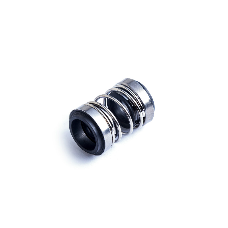
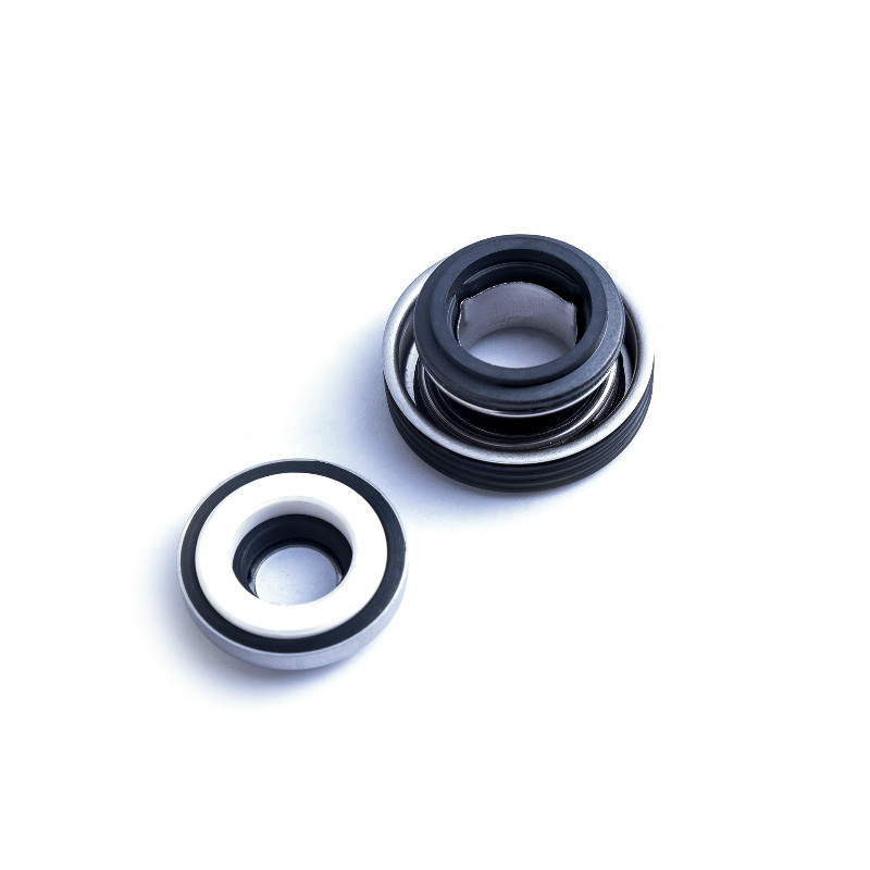
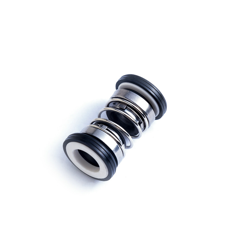
Burgmann mechanical seal MG1/MG12/MG13 is a famous elastomer bellows seal widely used in many kind of industry, like Process industry, Chemical industry, Pulp and paper industry, Water and waste water technology, Food and beverage industry, Sugar industry, and so on.
And for different using, there several type of the rubber tail, a middle long tail is MG12 mechanical seal, and longest tail is MG13 type. Please choose the right type tail when buying this burgmann mechanical seal MG1 type.
Guangzhou Lepu machinery CO., LTD becomes one of the leading mechanical seal supplier in south of china, we focus in designing and manufacturing mechanical seal for many kinds of famous brand pumps, our mechanical seal cover many kinds of industry like food, petrol chemical, paper making, sea ship, and so on.
1. Based in rapidly developing China market, Guangzhou Lepu Machinery CO., LTD has become one of the key market players in developing and manufacturing burgmann mechanical seal m7n .
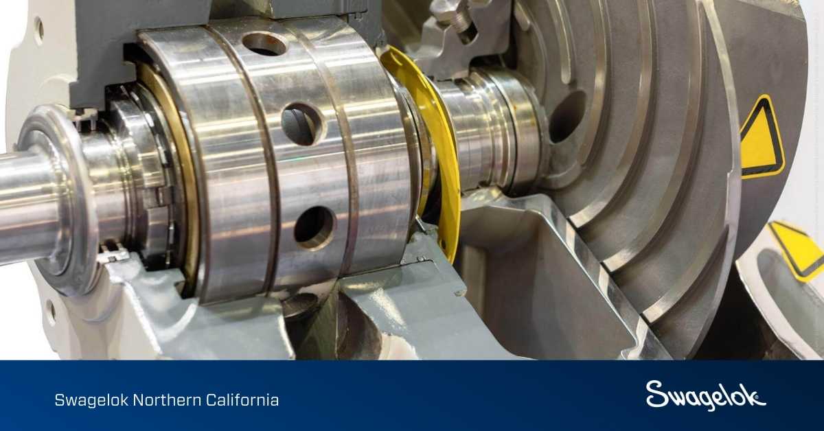
Extreme temperatures characterize many refinery processes. Gasoline boiling between 90° and 220° F seems low when compared to kerosene at 315° to 450° F and gas oil at 450° at 800° F. Asset reliability is critical to running these high-temperature processes round the clock. You can reasonably make the case that every major asset and component is critical to an efficient refining process.
But here I want to emphasize the importance of pumps, mechanical seals, and seal support systems. Without pumps, there is no process. Without the proper seal support systems, high temperatures in seal chambers may damage mechanical seals and lead to pump leakage.
While leakage can cause small problems or big ones, you always need to have the risk of sanctions in your mind, especially in high regulation states like California. And with Bay Area refinery budgets as lean as they are currently, it makes sense to choose the right systems from the start to avoid something costly going wrong in the future.
Several factors contribute to high temperatures in the seal chamber, which in turn leads to mechanical seal degradation. A mechanical seal and seal support system may have been perfectly matched to the initial process, working reliably for years. However, a change to a higher-temperature process can exceed the capability of the mechanical seal and capacity of the seal support system.
At higher temperatures, elastomeric components in the mechanical seal may begin to deteriorate. For example, beyond 300° Fahrenheit (150° C) ethylene propylene components eventually degrade and leak. Some hydrocarbons coke at higher temperatures and impede the free movement of mechanical seal components. And process fluids at high temperatures are prone to vaporize, or flash, across the seal faces, causing fugitive emissions.
With increased temperatures of process fluids, the seal support system may no longer be able to maintain the barrier or buffer fluid temperature or flow rate required to maintain the integrity of a dual seal arrangement. When mechanical seals and seal support systems can no longer ensure pump reliability it’s time to select seals, support systems, and components better suited for the job.
If a change to a higher process temperature is causing unanticipated leakage, consult with your preferred mechanical seal vendor. The materials alone can present an overwhelming number of options as seal technology and design continue to evolve. There are now more choices than ever, including:
⇒ Seal faces—carbon, stainless, ceramic, tungsten, and variants incorporating silicon, graphite, or nickel—engineered for resilience and compatibility with process fluids
The benefit of these choices is the ability to match mechanical seals to the specific needs of the process, maximizing seal performance and reliability.
The mechanical seal requirements of high-temperature hydrocarbon processes are best met with dual/ between seal arrangements. A dual seal support system provides fluid between two seals, buffer fluid at a lower pressure than the process fluid, and barrier fluid at a higher pressure than process fluid.
In contrast to a single mechanical seal arrangement where seal degradation or failure results in fugitive emissions or outright leakage, the two seal arrangement provides a more reliable means of preventing high-temperature hydrocarbons from leaking. Here too, rotating equipment and reliability engineers have a number of dual seal design options to choose from, including:
Face-to-face configurations are used in space-constrained areas that cannot accommodate back-to-back or tandem arrangements. Seals share a common stationary component which, if compromised, leads to leakage. You can select from buffer or barrier fluid options.
Gradual or sudden changes in barrier or buffer fluid pressure provide evidence of problems with seals. An experienced mechanical seal vendor can help you navigate the options available to ensure mechanical seals and their components meet each of your specific needs.
Equally important to the reliable functioning of mechanical seals in high-temperature processes is the selection of seal support systems. The mechanical seal you choose will guide the seal support system plan that best meets your needs.
Seal support systems for dual seals are divided into two categories: buffer and barrier. While that seems to simplify the selection, there are a variety of options for each category. To give you an idea of what’s available, I’ve listed a few of the mechanical seal support system options below.
Circulates pressurized barrier fluid from a reservoir to the dual seals. Use plant nitrogen, bladder accumulator, or piston accumulator to supply seal pot pressure. Any leakage across the process side seal is barrier fluid that lubricates seal faces and migrates into process fluid.
Provides clean, dry pressurized barrier gas (typically nitrogen) to the dual seals from an external source. Any leakage past the atmospheric seal is pure nitrogen.
For each of these plans, there are options to fine-tune the seal support system and provide a greater level of reliability for mechanical seals operating in high-temperature environments. Among the many options you may want to include:
An experienced seal support vendor can save you time and money, helping you select and configure the seal support systems with the right components for each of your high-temperature hydrocarbon pumping needs.
Swagelok has been meeting the mechanical seal support system needs of Northern California refineries for more than 50 years. When you work with Swagelok, you have the benefit of a local vendor with facilities in Concord, Fremont, and Santa Clara. Being local translates into on-site support, field verification of your requirements, and rapid delivery of seal support system assemblies, components, and parts.
To find out more about howSwagelok Northern California can help you address the challenges of maintaining the proper environment for mechanical seals in high-temperature serviceContact our team today by calling 510-933-6200.
Paul holds a B.S. in Mechanical Engineering from North Dakota State University. Before joining Swagelok Northern California, he was the West Coast Regional Sales Manager for an organization involved in pneumatic and hydraulic applications where he supervised product distribution throughout the western United States, Canada, and Mexico. While in this role, he was able to help provide technical and application-specific expertise to customers and distribution to drive specifications.
-1.jpg?width\u003d951\u0026name\u003dimage2%20(1)-1.jpg)
Utex has decades of experience designing and manufacturing mechanical seals for a broad spectrum of industries. Using CAD/CAM technology, we design and manufacture our own
Our years of experience and engineering expertise give us the know-how to handle pumping problems whether it takes a simple balance modification or an entire custom-engineered seal. This gives our customers the option of ordering high-quality seals for highly specialized applications while maintaining cost-efficient economies.
We have the flexibility to design custom seals and associated parts for high temperature applications, corrosive material service, for high durability operating requirements and for handling all types of fluids. It is a total sealing technology capability that Utex offers.
The shaft seal is a sealing element which seals the rotating shaft, of a centrifugal pump where it passes through the non-rotating pump casing reducing fluidleakage to atmosphere or the entry of air from outside to a certain level, and keeps wear of the sealing faces as low as possible.
Pumps are specially designed and manufactured to cater for a whole range of different applications. This process takes into account aspects such as resistance to the fluids handled, temperature and pump pressure. The appropriate seal type for the individual pumping requirements is chosen from a wide variety of different shaft seals.
The design is based on one of the two following principles: sealing by means of a narrow radial gap (parallel to the shaft axis) or a narrow axial gap (at a right angle to the shaft axis). For both sealing principles, the gaps may either employ a contact or non-contact design.
If only non-contacting controlled gap seals are used, a considerable amount of leaking fluid can always be assumed. This sealing system is therefore less suitable for environmentally harmful fluids handled.
Shaft seals are by their nature susceptible to leakage, and with some types leakage is actually essential to ensure proper sealing functioning. The suggestion that a seal shaft provides "zero leakage" is therefore misleading. However, depending on the seal type chosen, the amount of leakage
can vary considerably. A volute casing pump with a circumferential speed at the sealing area of 20 m/s and a pressure to be sealed of 15 bar which uses a gland packing for sealing has a leakage rate of about 5 – 8 l/h, while the leakage rate of a mechanical seal used under the same conditions is only approx. 6 cm3/h (0.006 l/h).
The leakage rate of 4 to 6000 l/h for a boiler feed pump sealed by a floating ring seal is particularly high; in this case, the diameter to be sealed is 200 mm and the pressure 40 bar, the
Due to differences in pump designs the individual seal types are not necessarily suitable for every type of application. The type of seal to be employed depends on the sliding velocity, the pressure to be sealed and the fluid temperature.
In the case of contact-type dynamic shaft seals, the parts to be sealed move relative to each other. For this reason lip-contact and line-contact shaft seals (e. g. lip seals) are only suitable for use with very low pressure differences such as those occurring when sealing against bearing oil, and are usually not adjustable.
The packings can be adjusted and are suitable for higher pressures and circumferential speeds than lip seals. Different packing variants are used depending on whether the pump is run in suction head or suction lift operation, or whether it handles clean or contaminated fluid.
As the leakage with gland packings is relatively high compared with mechanical seals, the former are mostly employed for environmentally friendly fluids only.
When used with hot water up to 180 °C, the gland packing must be fitted with a cooling jacket. For higher temperatures cooling is ensured via a combination of an internally cooled shaft protecting sleeve and a cooling jacket.
If the pump is used in suction lift operation, a barrier fluid line and a lantern ring fitted after the first packing ring ensure that air cannot enter via the packing. Provided the pump handles a clean fluid, this barrier fluid is supplied via the pump"s See Fig. 5 Shaft seal
As the barrier fluid pressure is higher than the pump pressure, a certain amount of the barrier fluid mixes with the fluid handled inside the pump, so that compatibility between the barrier fluid and the fluid handled should be ensured.
When the gland packing is serviced, both the packing cord and shaft protecting sleeve must be assessed for wear. If the shaft protecting sleeve has a hard, wear-resistant surface, this generally has a positive effect on the gland packing’s service life. Chrome plating, surface nitriding or plasma coating are excellent methods for hardening shaft protecting sleeves at the area subject to packing ring abrasion. Surface hardness should be higher than 800-1000 HV (Vickers hardness).
Unlike gland packings, mechanical seals have a sealing gap which is positioned at a right angle to the shaft axis. These shaft seal designs are also called axial or hydrodynamic mechanical seals. Compared with gland packings, they require less space and no maintenance.
Mechanical seals are well-suited for sealing low and high pressures and circumferential speeds. The risk of inappropriate operation is therefore very low.
However, considerable disadvantages arise through wear caused by abrasive fluids (see Abrasion). As is the case with gland packings, clean barrier or flushing fluids (e. g. cleaned by means of cyclone separators) help to keep abrasive particles away from vulnerable seal faces.
Pressed together by hydraulic and mechanicalforces, two seal faces slide relative to each other during operation. The sealing gap lies between these precisely machined seal faces and is filled with a lubricating film, generally a liquid. The sealing gap width (i.e. the distance between both seal faces) is influenced by various factors, including the seal faces" surface quality (i.e. how rough or smooth they are) and the sliding velocity.
Leakage from mechanical seals is very low; the fluid leaks into the atmosphere in the form of vapour or droplets. To calculate the mechanical seal"s leakage rate, a gap width of under 1 μm is normally assumed. Thanks to this extremely narrow gap, the leakage rate for mechanical seals is considerably lower than that for shaft seals with radial gaps.
A further important differentiating feature is that seals can be unbalanced and balanced. In the case of unbalanced mechanical seals, the seal face is exposed to the complete pressure to be sealed.
If the k value becomes smaller, the seal face loads are reduced. For this reason, only balanced mechanical seals are employed in high-pressure and high-velocity applications.
A low k value results in both an improved lubricating film and a higher leakage rate. However, an excessively low k value may in extreme cases cause the complete separation of the seal faces resulting in a loss of the sealing effect.
Alongside the hydraulic closing force, spring forces provide an additional axial force acting on the sealing gap. The springs can employ an open or enclosed design and be in contact with the fluid handled or not; they may or may not transmit torque.
The friction losses generated are lower than those of gland packings. Heat is generated in the shaft seal housing due to friction; depending on the amount produced, it can be dissipated either via convection from the seal housing to the atmosphere or via forced circulation through an externally installed heat exchanger.
Frequently used designsSingle, unbalanced mechanical seal as a typical example for a centrally arranged, conical single spring: The variant shown here is for "dead end" installation, i.e. there is no additional fluid circulation in the mechanical seal area.
Unbalanced mechanical seals are used for pressures of up to max. 15 bar and sliding velocities of up to max. 15 m/s. In general, a sufficient proportion of friction heat generated in the sealing gap can be transferred to the fluid handled and dissipated from the shaft seal housing to the atmosphere via convection. If the fluid handled is cold, the friction heat is absorbed by the fluid itself. One variant is the rubber bellows seal (bellows-type mechanical seal).
Unbalanced mechanical seal with stationary spring assembly: this design is used for higher sliding velocities and ensures the springs can reliably fulfil their task (rotary spring assembly would entail a risk of broken springs due to high centrifugal forces).
Varying spring arrangements are just one example of the distinctive features represented in the wide range of mechanical seal designs tailored for various operating conditions.
In the case of "back-to-back" arrangements, a barrier fluid is fed into the space between the two mechanical seals. Its pressure should be approx. 10 %, and at least 2-3 bar, higher than the pressure of the fluid handled by the pump.
As the barrier fluid absorbs the friction heat generated by the two mechanical seals, it must be circulated, i.e. removed from the seal cavity, cooled and returned to the seals.
The barrier fluid pressure is generated by a barrier fluid system (thermosyphon vessel) or pressure booster. In the case of tandem seals, the space between the seals is flushed by unpressurised quench liquid (quench). If the leaking fluid handled by the pump has a tendency to crystallise when in contact with air, a seal arrangement comprising two rubber bellows seals should be used. It is important that the quench liquid and fluid handled are compatible.
Instead of using an outboard mechanical seal, it is also possible to install a simple sealing element such as a lip seal or packing ring. It is fitted as a back-up seal for the main seal to prevent leakage (e. g. in the case of hazardous fluids) and to safely and reliably dissipate heat.
Tandem seals are employed when a high internal pump pressure requires distribution to two mechanical seals. The barrier fluid pressure level then lies between the pressure to be sealed and the atmospheric pressure. The pressure handled by the inboard seal corresponds to the difference between the pressure to be sealed and the barrier fluid pressure; the pressure handled by the outboard seal corresponds to the difference between the barrier fluid pressure and the atmospheric pressure. The barrier fluid must circulate in order to dissipate the friction heat generated by the seals.
These mechanical seal types are used in the boiling or pressurised water reactors of nuclear power stations and are installed in main coolant pumps to seal extremely high pressures.
The pressure must be distributed via an auxiliary system, e.g. a three-stage cascading system of throttles arranged in the seals" bypass lines. A defined amount of water flows via the bypass line. Pressure is thus reduced by approx. 33 % at each throttle. The reduced pressure at each stage"s output is the operating pressure for the next stage"s input. This throttling and recirculation of the barrier fluid ensures the pressure is reduced and the friction heat removed from the sealing stages.
In the case of boiler feed pumps, seals have to cope with high sliding velocities, heat transfer from the fluid handled and the heat generated by friction.
The sealing gap temperature is generally higher than the fluid temperature in the seal housing. The latter can be kept well below 100 °C by circulating the fluid through to an external cooler by means of suitable pumping devices inside the pump. Pumping screws, holes in the shaft protecting sleeve or small pumping discs serve as pumping devices.
Magnetic filters ensure that the circulated water is absolutely clean. With high-specific speed pumps,a venting tank is essential to reliably remove any air from the circulation liquid.
Detrimental dry running of the mechanical seal may occur if the pump is operated without liquid fill and in the event of a major ingress of gas, a high gas content or the evaporation of the fluid handled. Due to its low density, the gas always tends to move to smaller diameters which is the sealing gap of seals in most cases. The presence of air in this space leads to dry running and also impedes sufficient heat dissipation from the sealing gap resulting in thermal overload of the seal faces and mechanical seal failure (heat stress cracks) within a very short time.
External cooling circuits are not used if the heat losses generated by the seal can be dissipated to the atmosphere via free convection and heat radiation.
Other forms of cooling comprise a fan impeller mounted to the pump shaft to intensify convection (forced convection). In both cases the seal housing is provided with fins, at a right angle to the shaft axis (without fan impeller) see Fig. 16 Shaft Seal, and parallel to the shaft axis (with fan impeller).
In the case of uncooled mechanical seals operated at high temperatures, the temperature in the sealing gap is generally higher than the temperatures in the sealing gaps described so far. This means that the boundary between the liquid and vapour phase in the sealing gap inevitably shifts towards the sealing gap inlet, increasing the risk of insufficient lubrication.
The sealing gap width between the stationary component and the rotating component is designed to be as narrow as possible in order to minimise leakage. However, it is important to ensure that the parts do no rub against each other. Leakage on a rotating shaft is slightly lower than during standstill.
The fluid flowing through the gap allows the pressure to be reduced in relation to the atmospheric pressure. On throttling gaps and floating ring seals this is achieved in the gap due to fluid friction and due to flow losses when the fluid enters or leaves the gap.
Floating ring sealThe major advantage of floating ring seals is the fact that the components are not in contact. However, the time and costs required to provide the barrier condensate, its treatment and relevant control equipment are substantial.
The floating ring seal consists of several short throttling rings fitted in succession which can move in a radial direction and centre themselves automatically due to the pressure distribution on the ring. A cold barrier condensate injected into the seal ensures that hot water from the pump does not escape to the atmosphere (controlled system). As long as the pump is in operation or under pressure, barrier water supply must be ensured.
The floating ring seal is occasionally employed in boiler feed pumps. Its barrier condensate quantity can be controlled via the barrier condensate"s pressure and temperature difference.
(Δt control), the difference between the temperature of the barrier condensate at the outlet and that of the injection condensate is defined. In the case of boiler feed pumps, the amount of feed water escaping from the inside of the pump is very low, while penetration of cold water into the pump can be ruled out.
For differential pressure control (Δp control), the difference between the injection pressure and the inlet pressure is defined. A very small amount of barrier condensate flows into the pump. This puts high demands on the cleanliness and gas-free condition of the barrier condensate required to prevent the main circuit from being contaminated.
Labyrinth sealThe labyrinth seal is a firm throttling bush with a circular groove profile. As radial movement is impossible with this type of seal, the diametral clearance must be wider
Centrifugal sealThis type of shaft seal generates pressure itself in order to counteract the differential pressure to be sealed; it is frequently backed up by a standstill seal. Designed as
spring-loaded mechanical seal, it is opened by centrifugal forces at very low speeds and thus protected against wear. See Fig. 20 Shaft sealThe actual centrifugal seal (fitted as an auxiliary impeller using a liquid ring at the outer diameter) operates contact- and wear-free.
Hydrostatic sealDue its design, proper functioning of the hydrostatic seal as a non-contact seal is only ensured at pressures from 20 bar. The pump drive must not be started until this pressure level is reached.
The gap"s stiffness is very high at full operating pressure (160 bar). To move the gap from its balanced position by 1 μm, an external force of approx. 4000 N would be
The gap with which the seal operates may be very narrow, but it is finite, and as such exhibits a considerable leakage rate (p = 160 = 160 bar, n = 1.500 = 1500 rpm; sealing diameter at 260 mm, Q = 800 = 800 l/h). It is therefore necessary to back up the hydrostatic seal with a low-pressure seal that provides sealing to atmosphere.
See Fig. 22 Shaft sealDue to the hydrostatic seals’ operating limitation at low pressures, they have been replaced with hydrodynamic mechanical seals in many nuclear power stations.
Static contact seals include O-rings. These are moulded seals and are defined as "rings with circular cross section made of elastic materials; they seal through the effect of slight bracing during installation, intensified by the operating pressure" according to DIN 3750. Their symmetrical cross-section rules out incorrect installation.
O-rings are employed on all the shaft seals described here. However, they can only be used as static sealing elements or to seal areas where slight axial movement is occasionally required.
They are manufactured at different hardness degrees, specified as shore hardness (A or D). The hardness scale ranges from 0 to 100, 0 being the lowest and 100 the highest hardness unit.
The majority of O-rings used on mechanical seals are elastomer rings with a shore A hardness of 70 to 90. These O-rings are used for sealing between the shaft sleeves and the shaft, and between the primary ring or the mating ring and the respective components they are connected with. They ensure that the spring-loaded seal component can follow small axial shaft movements.
Their significance is often underestimated: ultimately, each shaft seal is only as good as its O-ring. O-rings must be matched to the fluid handled, cover a defined temperature range and provide good ageing resistance. Moreover, it is important to use a high-quality O-ring grease which meets the operating requirements. Besides providing long-term lubrication, the grease must be compatible with the fluid handled and must not attack the O-ring.
Elastomers which swell less than 10 % in the operating fluid and do not chemically react with the fluid handled are suitable for use as a mechanical seal"s secondary seal. A number of elastomers are available for this purpose which react differently in a reference oil with regard to temperature
An end face mechanical seal is a device intended to prevent or minimize leakage from a vessel through the clearance around a rotating shaft entering that vessel. Perhaps the most common example is the end face mechanical seal used in the water pump of an automobile engine. Most pumps used in petroleum refineries, chemical plant and pipelines also use end face mechanical seals.
The simplest possible mechanical end face seal consists of a shoulder on a rotating shaft which rubs against a stationary case. This concept is shown in Figure 3.
As with packing or any bearing material, lubrication and cooling are required to prevent heat buildup and wear. Hydraulic pressure tends to force fluid between the faces and provide a lubricating film but the face separation must be kept very small to minimize leakage. Cooling is provided by the surrounding liquid. The conceptual design shown in Figure 3 is very simple, but it demonstrates the basic principle of the end face mechanical seals. Of course, it has functional drawbacks which must be addressed.
Seal face leakage is governed by many variables, but the dominant variable is face separation. A variation of a few micro-inches (millionths of an inch) in the face separation can cause significant changes in leakage. Unfortunately, shaft movement can amount to several thousandths of an inch.
A practical approach to overcoming shaft movement is to mount one of the seal faces in a flexible manner so that it can move axially. Obviously a desirable feature, this flexibility is a prerequisite for effective seal design.
Figure 4 shows an improved seal as compared to Figure 3. In Figure 4, The sealing shoulder on the shaft has been removed and replaced with a component which is not permanently attached to the shaft. This component is called the primary ring. The “face” of the primary ring rubs against the mating ring. Since the primary ring and the shaft are two separate parts, an additional sealing device must be used to prevent leakage between the shaft and primary ring. The flexibly mounted primary ring can compensate for the small variations in movement on the axial plane. It can also adjust for seal face wear. Figure 4 is a very simple mechanical seal but it illustrates the concept used by the majority of mechanical seals. Of course, some additional components are required to preload the faces, transmit torque and provide ease of installation.
Figure 5 shows a more complete mechanical seal including a replaceable mating ring, “O-ring” gaskets, springs, setscrews and various other hardware. As will be seen later, the design of these components may vary considerably according to the required service for the seal. In addition, the assembled components themselves may be arranged and oriented in various ways to accomplish varying degrees of sealing, reliability and redundancy.
In a mechanical seal, the primary leakage path is between the seal faces. Naturally, increasing the face separation increases the leakage. In fact, as will be shown later, doubling the face separation can increase the leakage rate by a factor of eight! This relationship between leakage and face separation provides a powerful incentive for minimizing face separation. In modern mechanical seals, face separations are so small (on the order of a few microns) that the leakage rate is affected by the surface roughness. The effective face separation is a combination of the surface roughness of the two mating parts and the fluid film thickness. This concept is illustrated in Figure 6. The seal manufacturer can control the initial surface finish by lapping and polishing. A typical seal face is flat to within 23 millionths of an inch. This degree of flatness is so small that refracted light rays must be used to measure it. The fluid film is established during initial start-up of the seal by hydraulic forces.
The principle of establishing a fluid film is essential to all seal designs. Most mechanical seals are designed to operate in liquids; these seals require a liquid film. Designing a seal to operate on a gas film is much more complex. Whether the film is gas or liquid, it reduces the gross contact between the rotating component and the stationary component. It also provides lubrication to reduce friction and wear. Without a stable fluid film, gross rubbing contact could damage the faces.
Mechanical seals may be classified by their design features and the arrangement of those features. The Design category includes the details and features incorporated into a single primary ring/mating ring pair. The Arrangement category includes the orientation and combination of the primary ring/mating ring pair. Figure 7 illustrates the classification of mechanical seals.
The Design classification considers the details which enter into the features of these components. Some examples of these features are balance, face treatment, rotating element, springs, secondary sealing elements and drive mechanism. In general, these design features are not completely independent; that is, emphasis of a particular feature may also influence other features. For example, selection of a particular secondary sealing element may influence the shape of the primary ring.
By definition, the primary ring is the flexible member of the mechanical seal. The design of the primary ring must allow for minimizing distortion and maximizing heat transfer while considering the secondary sealing element, drive mechanism, spring and ease of assembly. Many primary rings contain the seal face diameters, although this is not a requirement of the primary ring. The primary ring always contains the balance diameter.
Balance. The term “balance” is frequently referred to as the relationship of hydraulic forces on a seal but it is actually a geometric ratio. Balance ratio is defined as the ratio of the hydraulic closing area to the hydraulic opening area. This ratio is customarily expressed in a percentage.
Figure 8 illustrates the concept of balance. In a seal, hydraulic pressure acts on the back of the primary ring; the resulting force pushes the faces together. This force is called the closing force and this area the closing area. Similarly, any pressure between the seal faces creates an opening force which tends to separate the faces. Therefore, the face area is also called the opening area. The balance ratio is simply the ratio of the closing area to the opening area.
As shown in Figure 8, the area above the seal face outside diameter is disregarded when the closing area is computed. This area is not considered because the pressure is the same all around it; consequently the contribution of the resultant of the hydraulic forces on this area is zero.
When the closing area is reduced, the closing force is reduced proportionally; this feature can be used to advantage when designing a seal. However, for a seal shape such as shown in Figure 8, the closing area will always be greater than the opening area. In order to make the closing area less than the opening area, the shape can be changed as shown in Figure 9.
The seal shown in Figure 8 is said to be an “unbalanced” seal. Its balance ratio is greater than 100% because of the necessary clearance underneath the mating ring. Typical balance ratios for unbalanced seals range from 120 to 150%. The seal shown in Figure 9 is said to be a “balanced” seal; its balance ratio is less than 100%. The balance ratio of “balanced” seals is typically from 65% to 90%.
The distinction between “balanced” seals and “unbalanced” seals is simply that balanced seals have a balance ratio less than 100%. A seal with 99% balance ratio is balanced, a seal with 101% balance ratio is unbalanced.
For a given pressure, balanced seals have less face load than unbalanced seals. Therefore, balanced seals are normally used in higher pressures than unbalanced seals.
Primary ring shape.The shape of the primary ring may vary considerably according to the incorporation of various design features. In fact, the shape of the primary ring is often the most distinct identifying characteristic of a seal. Figure 10 shows four examples of typical primary ring shapes.
Figure 10a represents a primary ring associated with elastomeric bellows seals. This primary ring has been optimized to take advantage of the elastomeric bellows and a large, single spring.
Figure 10b represents a primary ring with an inserted seal face. Insert faces must be designed with care because temperature differentials can cause differential expansion between the adaptor and the primary ring. Insert designs can also have problems associated with mechanical stress and distortion.
Figure 10c and 10d show how the shape of the primary ring is influenced by the secondary sealing element. Figure 10c is a primary ring designed to work with a wedge. Figure 10d is designed to work with an O-ring. Also, Figure 10c shows an unbalanced shape while Figure 10d is a balanced shape.
Face Treatment.The most common seal face design is a plain, flat surface but there are many special treatments designed for specific applications. Figure 11 shows some of the more common face treatments. The plain, flat face is most common. In general, face treatments are a means of modifying the pressure distribution between the seal faces. The most common objective is to increase the opening force and thereby reduce the magnitude of the mechanical contact. Face treatments may be considered to produce hydrostatic or hydrodynamic forces.
The simplest face treatment is a plain face that is not flat. This design produces forces that are primarily hydrostatic. Figure 11b shows an example of a face that is lapped so that it tends to touch the mating ring at the inside diameter. This means that the leakage path is converging. Although this is a simple concept, it is actually difficult to lap the required taper with the desired accuracy. Too little taper will allow some rubbing to occur at the ID which will change the taper. Too much taper will cause gross separation of the faces with the resulting high leakage.
Rotating Element. Although most illustrations have shown the primary ring to be rotating with the shaft, either the primary ring or the mating ring may be used as the rotating element. Seals with rotating primary rings are said to be “rotating” seals; seals with stationary primary rings are said to be “stationary” seals. Because the springs are always associated with the primary rings, sometimes the distinction is made as “rotating springs” versus “stationary springs”.
For convenience, rotating seals are used in most equipment. Pump shafts are already made of a comparatively high grade material and manufactured to close tolerances. This makes pump shafts well suited for rotating seal applications. Assembly of rotating seals can generally be done directly on the shaft or by using a relatively simple sleeves. Figures 5, 8 and 9 all show rotating seals with stationary mating rings.
Stationary seals have some advantages over rotating seals. In small, mass produced seals for modest services, the entire seal may be placed in a package which minimizes shaft and housing requirements for the equipment. Figure 13 shows a low cost stationary seal. Stationary seals are also used to advantage in large sizes or at high rotational speeds. Above 5,000 to 6,000 fpm, a rotating primary ring (which is flexible, by definition) may require dynamic balancing (for rotational imbalance) in order to operate in a stable mode. A stationary primary ring does not require this balancing. On the other hand, the stationary seal does require a close bore tolerance. This close bore tolerance is usually a second manufacturing operation on most equipment. Stationary seals sometimes incorporate special design features such as auxiliary liners, sleeves or adapters to help retain the mechanical advantages of the seal. Figure 14 shows a stationary metal bellows seal used in high temperature centrifugal pumps.
By definition, the mating ring is the non-flexible member of the mechanical seal. The design of the mating ring must allow for minimizing distortion and maximizing heat transfer while considering ease of assembly and the static secondary sealing element. The mating ring can contain the seal face diameters, although this is not a requirement of the mating ring. To minimize primary ring motion, the mating ring must be mounted solidly and should form a perpendicular plane for the primary ring to run against. Figure 15 shows some typical mating rings.
O-Ring. Figure 15a-c shows a mating ring which uses an O-ring. This is a simple arrangement but is limited to the temperature and chemical compatibility range of the elastomer.
Floating. Figure 15d is the floating ring type. This design offers the flexibility of using teflon, grafoil, or an O-ring (Figure 15c) for the secondary sealing item. If teflon or grafoil is used, a pin should be added to prevent rotation due to the low coefficient of friction of these materials.
Cup Mount.Figure 15e, the cup-mounted construction, offers a low-cost arrangement which can be used with surface finishes over 63 rms. It is limited on high temperature applications and to lower pressure ranges because of the insulation effect of the cup.
Clamped-In. Figure 15f represents a clamped-in mating ring design. A clamped-in design uses a series of gaskets to prevent leakage between the mating ring and the pump casing or gland. This design has a wide temperature range since it can be used with spiral-wound metallic gaskets.
The secondary sealing elements are gaskets which provide sealing between the primary ring and shaft (or housing) and the mating ring and shaft (or housing). They are called secondary sealing elements because their leakage path should be secondary to the seal face leakage. Loading by hydraulics or mechanical force makes the secondary seal tight in its confined area. The secondary sealing element for the mating ring is always static axially (although it may be rotating). Secondary sealing elements for the primary ring are described as being either pusher or non-pusher in the axial direction. The term pusher is applied to secondary seals that must be pushed back and forth by the movement of the shaft or primary ring. A non-pusher secondary seal is a static seal for the primary ring.
Pusher type secondary seals have the disadvantage of damaging the surface to which they must seal. This damage, called fretting, is caused by the cyclic movement of the secondary sealing element as the shaft rotates. In contrast to the pusher design, a non-pusher secondary sealing element could not cause any fretting.
On the other hand, this rubbing and dragging effect is also an advantage of the pusher design because it adds damping and therefore stability to the seal. This damping can make a significant difference in performance for some services.
Figure 16 shows examples of pusher, non-pusher and static secondary seals. The pusher design may use O-rings, wedges, etc. The non-pusher is always some sort of bellows with a static section. Mating rings use various static gasketing and O-ring designs.
Bellows. Figure 16a is a full convolution elastomeric bellows. It offers the greatest possible flexibility to the front section of the primary ring. The front section of this bellows has minimum contact with the shaft or sleeve, thus minimizing wear and hang-up. The large tail section provides a considerable sealing area to compensate for imperfections in the shaft. There are also are variations of the full convolution design that use a half convolution. Its ability to accept axial motion is reduced, due to the one-half convolution design.
Figure 16b is a bellows made out of teflon or glass-filled teflon combinations. This seal which is designed for the extremes of corrosive environments, provides the advantages of the non- contacting bellows convolution. Because it is made out of teflon, support rings or a drive collar is required to attach the tail section or the bellows to the shaft. Due to the requirements of flexibility, the convolutions must be considerably larger in cross-section than the typical elastomeric bellows design.
Figure 16c is an all-metal bellows style seal. It has the inherent advantage of flexibility associated with bellows design for high temperature applications. Due to its all-metal construction, it offers considerable freedom of design since it is not restricted to the temperature and chemical limits of elastomers. Metal bellows are constructed of individually welded metal leaves approximately .004/.012 thick. A large number of leaves are required to provide the maximum amount of flexibility associated with other styles of bellows seals. The mechanical closing force that is provided by the spring on other seal designs is accomplished by stressing the bellows from free height in this design. Metal bellows seals are inherently balanced because of the manner in which the bellows becomes distorted when pressurized.
“V” Rings, “U” Cups and Wedges. Figure 16d is a wedge. Wedges are typically made of TFE material. They are considerably more flexible than the “V” ring or U-cup arrangement because they operate on the ball-and socket principal. Special manufacturing fits are not a requirement for wedges because of the shallow angle of contact between the primary ring and the shaft. However, it does require a polished surface for effective sealing (32 rms with polish).
In addition to wedges, there are U cups and V rings. Their construction as a secondary seal offers limited amounts of flexibility and requires extremely close tolerances on the cross-section fits. The “V” rings are generally manufactured in TFE or TFE-filled material, requiring pre-loading of the rings to activate the point contact on the lips. Because of the “V” ring design, it can be used at high pressures but it is the least flexible, and most rigid of the secondary seal designs. Because of it’s construction, the “V” ring cannot flex to compensate for motion and it must be pushed along the shaft to take up wear at the seal faces. Shaft and primary ring finish must be highly polished (15 rms) in order for this type of secondary seal to operate leak-free.
O-Rings. Figure 16e is the O-ring. This is by far the simplest and most popular secondary sealing element. It has been used successfully over a wide temperature range and in a variety of fluids. O-rings are considered to be self-energizing seals and do not require much mechanical preloading. This feature allows O-rings to be used at very high pressures. O-rings are offered in a complete range of chemical resistant and general service compounds. Buna-N, Neoprene, Ethylene-Propylene, Viton, and Kalrez are typical materials selected for a variety of service conditions. On the other hand, Teflon does not make a good O-ring material, particularly if the O-ring is to be dynamic.
There are encapsulated O-rings. This is an attempt to obtain the chemical resistance offered by Teflon and the flexibility of the elastomeric O-ring. Unfortunately, the result is dominated by the hardness of the Teflon outer shell. The recommended surface finish of the shaft/sleeve is 15 rms. The encapsulated “O” ring is sensitive to temperature fluctuations. Because of these limitations, encapsulated O-rings are usually recommended only for static sealing.
In every mechanical seal there is always a need for keeping the faces closed in the absence of hydraulic pressure. Generally, a mechanical device in some form of spring is used. Figure 17 shows some of the different types of springs used in mechanical seals.
Single spring.A single spring seal has the advantage of comparatively heavy cross section coil which can withstand a higher degree of corrosion. Another advantage is that single springs do not get clogged by viscous liquids. The disadvantage of a single spring is that it does provide uniform loading characteristics for the faces. Also, centrifugal forces may tend to unwind the coils. Single springs also tend to require more axial space and a specific spring size is required for each seal size.
Multiple springs.Multiple springs are usually smaller than single springs and provide a more uniform load at the faces. The same spring size can be used with many seal sizes by simply changing the number of springs that are used. Multiple springs resist unwinding from centrifugal force to a much higher degree than a single coil spring since the forces act differently. The most obvious disadvantage of small springs is the small cross section wire. This makes the smaller springs subject to corrosion and clogging.
Wave spring. The next form of spring generally considered is the wave type, simple described as a washer into which waves have been formed to provide a given amount of mechanical loading . The main reason for using this type of spring is that it requires even less axial space than the multiple spring design. On the other hand, special tooling must be made for best manufacturing results. Further, the tempering required on this design limits materials to those which are not as corrosion resistant as the high grade stainless and Hastelloy groups. Also, when using wave springs, a greater change in loading for a given deflection must be tolerated. That is, a great deal of force loss or force gain, with comparatively small axial movement must be expected.
Belleville washer.The Belleville washer is a very stiff spring; in fact, the normal problem with the Belleville washer is that the spring rate is to high. To reduce the spring rate, the washers are stacked.
Metal bellows. A metal bellows is actually a combination of a spring and secondary sealing element. Welded edge metal bellows resemble a series of Belleville washers. Formed bellows may be used to reduce the quantity of welding; however, a formed bellows has a much higher spring rate than a welded bellows. The bellows thickness must be selected for resistance to pressure without an excessive spring rate. The welding technique and bellows shape must be selected for maximum fatigue life.
The term “hardware” is used to describe the various devices which hold the other components together in the desired relationship. For example, a retainer might be used to package the primary ring, secondary sealing element and springs into a single unit. Another example of hardware is the drive mechanism which is necessary to prevent axial and rotational slippage of the seal on the shaft.
A drive mechanism is required because of the torque created between the seal faces. Both static and dynamic drives are required. The static drive is only required to hold an axial position and transmit torque. The dynamic drive must transmit torque and allow for the axial flexibility of the primary ring. Figure 18 shows some variations of drive mechanisms. Dedicated devices made of strong materials are said to be positive drives and are generally preferred in the heavy duty seals.
Key drive.This is one of the more rugged forms of drive. In high pressure, comparatively large size units, the ruggedness of this type of drive is in keeping with the balance of the sturdy features incorporated in seals for high pressure applications.
Slot. This is another of the more rugged methods of engaging metal to metal, especially when the slots and mating ears are used in multiple forms. It is one of the best methods to assure positive engagement between two parts that have relative axial motion between them. Its basic design also allows for the high degree of flexibility generally incorporated in the primary ring.
Elastomer Drive.This is not a positive drive method and is generally limited to light duty seals; however, it is extremely simple, economical and effective for some services.
Spring drive.Another effective drive mechanism for light duty seals is to incorporate the drive into the springs. Care must be taken in this design as to the direction of rotation, corrosion rate and spring rate.
Although all end face mechanical seals must contain the five elements described above, those functional elements may be arranged or oriented in many different ways. Several dimensional and functional standards exist, such as API Standard 682 – Shaft Sealing Systems for Centrifugal and Rotary Pumps, which describes the configurations for used in Oil & Gas applications. Even though the scope of API 682 is somewhat limited, it may be extended to describe end face mechanical seals in general.
Configuration refers to the number and orientation of the components in the end face mechanical seal assembly. For example, springs may be rotating or stationary. Single or multiple pairs of sealing faces may be used. For multiple seals, the individual pairs of sealing faces may be similarly oriented or opposed. Containment devices such as bushings may or may not be used as part of the configuration.
Single seals. The vast majority of all seals fall into the single seal category. In this category the seal can be mounted so that it is inside the process liquid or outside the process liquid. Inside mounted seals are easier to cool and generally can seal higher pressures. Also the direction of leakage is opposed by centrifugal force. Inside mounted is by far the most popular, see Figure 19.
An outside seal is shown in Figure 20. Outside seals have minimal contact with the process liquid. This is an advantage in sealing corrosive liquids providing that overheating is not a problem. A disadvantage of outside seals is that the direction of leakage is the same as centrifugal force.
Multiple seals. Multiple seal arrangements can provide environmental controls and/or redundancy. The most common types of multiple seal arrangements were previously called double and tandem but are called Arrangement 2 and Arrangement 3 by API 682. The double seal emphasizes environmental controls while the tandem seal emphasizes redundancy.
The principal purpose of the tandem seal is to provide redundancy. The two seals are oriented so that the outer seal can accomplish the sealing task if the inner seal fails. A tandem arrangement is shown in Figure 21. Because of this redundancy, the outer seal is sometimes called the “backup” or “safety” seal. Tandem seals use a buffer fluid to lubricate and cool the outer seal. The inner seal operates in the process liquid and is cooled by that liquid. Any leakage from the inner seal must be contained by the outer seal and buffer system. The buffer fluid is normally at a pressure less than the stuffing box pressure. In order to keep the buffer pressure low, the buffer system is vented continuously.
Tandem seals (API Arrangement 2) are also used in “stages” (perhaps this is the origin of the name “tandem”) when process pressures are extremely high. When tandems are used in stages, the buffer system is pressurized to some intermediate pressure, typically half the stuffing box pressure.
The double seal (API Arrangement 3) uses two primary ring/mating ring pairs oriented so that a pressurized barrier liquid is maintained between them as shownin Figure 22. On double seals, the inner seal seals between the process liquid and the barrier liquid. Because the barrier system is at a greater pressure, any leakage is barrier liquid. The outer seal seals between the barrier liquid and the atmosphere. In most cases the barrier liquid is circulated and cooled to prevent heat buildup.
Notice that Figure 21 and 22 are identical. The only differences are the design of the faces and balance diameter and these details are not shown. This is somewhat controversial and many would describe both Figure 21 and 22 as being “tandem” because of the orientation of the components. Traditionally, a “double” seal would have the primary rings in a back-to-back orientation; however, for purposes of operation, either face-to-back (shown) or back-to-back may be used.
The biggest problem with the double seals is maintaining the barrier liquid at a higher pressure than the stuffing box. It is generally recommended that a 20 psi or 10% differential in favor of the barrier be maintained at all times.
In the past, double seals were described as primary ring/mating ring pairs which faced in opposite directions. A classic double seal is shown in Figure 24. This is usually true but is not a requirement of the double seal arrangement. Similarly, a tandem arrangement was frequently described as seal pairs facing the same direction, see Figure 21. Again, this is not a requirement. In a tandem arrangement, the buffer fluid is at the lower pressure and is continuously contaminated by leakage of the product across the primary seal. In a double seal arrangement, the barrier fluid is at the higher pressure and the product fluid is continuously contaminated by leakage of the barrier fluid across the primary seal.
Double seals (API Arrangement 3) are used with API Piping Plans 53A, 53B, 53C or 54. Tandem seals (API Arrangement 2) are used with API Piping Plans 52and 55.
The term “adaptive hardware” is applied to hardware designed to simplify the incorporation of the primary ring and mating ring into the equipment which requires the mechanical seal. The most common examples of adaptive hardware are the sleeve and gland.
When the components are pre-assembled onto a sleeve and gland plate, the complete assembly is called a cartridge seal. This complete assembly can be easily slid onto the shaft and bolted in place thus reducing the potential for installation errors. Some cartridge seals use regular component seal parts whereas other cartridge seals might use specific purpose parts. API 682 specifies that only cartridge seals are acceptable to the standard.
Figure 23a shows the plain integral type gland plate which, if lapped on the sealing surface and gasketed perfectly to the face of the box without distortion, can serve as a sealing face against the rotating seal head. It is an item utilized on many compressor installations, showing that when applied correctly, even a gas such as Freon can adequately be sealed with this type of design. It becomes a desirable feature, especially where axial room is at a premium. It must be considered only where practical. If a relatively large bolt circle in relation to the shaft size is inherent in the unit, this design may prove uneconomical.
Figure 23b is a plain end plate with a pressed-in seat element. Some seal manufacturers advocate this design and it can be utilized where its stresses, replacement features and economics can be tolerated.
Figure 21c shows a so-called plain gland plate but with an O-ring seat added. Where the use of the integral gland plate is not practical from the standpoint of replacement cost or because the seat material itself must be of a higher grade material than it is practical for the endplate, this type of design becomes useful.
Still another auxiliary feature is termed the quench type gland plate. This gland type incorporates an entrance for liquid behind the seal face on the atmosphere side. Two other desirable features are to be gained from this quench gland-one is the safety provided by the throttling effect on the escaping liquid if the seal fails; the other relates to toxic liquids. If the liquid handled is toxic-instead of using the quench gland with a secondary liquid, the liquid can be vented to a safe area.
Sleeves are employed as an adapter from the seal requirements to the shaft requirements of the equipment. For example, the seal may require different diameters, as in a balanced seal. Figure 24 shows the two most common types of shaft sleeve.
Figure 24b is the “cartridge” or “package” sleeve. This design allows the complete seal, gland and sleeve to be assembled before it is installed in the pump.


 8613371530291