
api mechanical seal plans pdf for sale
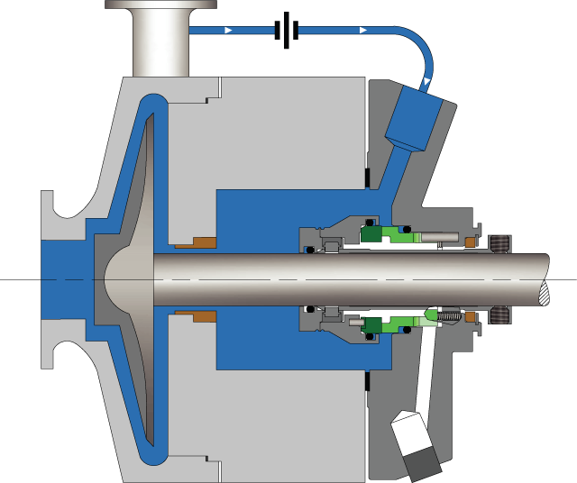
API Plan 11 recirculates flow from a high‐pressure section of the pump, typically the discharge piping, through a flow control orifice to the seal. Plan 11 is the default flush plan for most pumps.
See page 11 of the Mechanical Seal Support Systems Application Guide for additional details and ordering information. Contact your authorized Swagelok sales and service center for information on optional components.

After more than five years of planning, the American Petroleum Institute (API) is preparing to release the 4th edition of API Standard 682 (ISO 21049:2011). The API 682 standard, which dates back to 1994 and is formally known as Shaft Sealing Systems for Centrifugal and Rotary Pumps, offers specifications and best practices for mechanical seals and systems to pump end users.
The standard’s latest edition began to take shape in 2006, when API formed a 4th edition task force to respond to end users’ questions and comments about previous editions. The task force soon realized that major changes, including reorganization and editing, would be necessary. While addressing every aspect of the resulting 4th edition (which is more than 250 pages long) would be impossible, this article summarizes the standard’s main points.
Those who use API 682 should understand the standard’s scope and remember that the standard does not include specifications for equipment outside that scope, such as engineered seals or mixers. Another important but often misunderstood point is that API 682’s figures are illustrative and not normative in their entirety.
For example, one of API 682’s figures shows a fixed throttle bushing combined with a rotating Type A seal, but seal manufacturers do not always have to combine these two components. The standard provides normative details in clauses and tables to help purchasers distinguish between requirements and suggestions.
The 4th edition continues to divide seals into three categories, three types and three arrangements. For all practical purposes, seal manufacturers can combine a seal’s component parts into nearly any orientation or configuration. Each orientation and configuration has advantages and disadvantages with respect to certain applications, performance and system disturbances.
Before the 4th edition, API 682 did not specify a minimum clearance between the inside diameter of a stationary seal part and the outside diameter of a rotating seal part. The 4th edition specifies this minimum clearance—typically the clearance between the sleeve and the mating ring. The specified clearances are representative of standard clearances that end users have used for decades. End users should not consider seal components to be “shaft catchers” to restrict shaft movement. The minimum clearance specified in API 682 also applies only to equipment within the standard’s scope. Equipment outside that scope, such as non-cartridge seals, older pumps, non-API 610 pumps and certain severe services, might benefit from larger clearances.
The new standard also updates the default bushings for the gland plate for the three seal categories. Fixed throttle bushings are now the default for Category 1 only, while floating bushings are the default for Categories 2 and 3.
While the 4th edition features the recommended seal selection procedure from the standard’s first three editions, it adds an alternative selection method in Annex A. Proposed by task force member Michael Goodrich, this alternative method recommends using material data sheet information to select a sealing arrangement.
Plans 66A and 66B are new to the standard, although end users have used them previously in pipeline applications. These plans detect and restrict excessive leakage rates in case of an Arrangement 1 seal failure.
The 4th edition now requires Plan 52, 53A, 53B and 53C systems to have a sufficient working volume of buffer or barrier fluid for at least 28 days of operation without refilling. As a point of reference, the default reservoir for Plans 52 and 53A has a three-gallon capacity, or pot, for pump shafts smaller than 2.5 inches and a five-gallon pot for larger shaft sizes. Plan 53C must have the same working volume of fluid as Plan 53A. For Plan 53B, the default bladder and accumulator sizes are five gallons and nine gallons, respectively. The design of Plan 53B systems can be complex, especially when ambient temperatures vary widely, and purchasers should become familiar with the calculations and procedures in the 4th edition’s Annex F tutorial. The new edition also discusses the option of adding a pressure gauge and isolation valve to check the accumulator or bladder’s integrity in a Plan 53B system.
The 4th edition has revised the data sheets in Annex C extensively to make them the same for all seal categories. Only two data sheets are included in the 4th edition—one in metric units and one in U.S. customary units. The new edition also folds Annex J into Annex E.
Previous editions of API 682 required metal plugs and anaerobic sealants when shipping new or repaired cartridges. After much debate, the task force decided that threaded connection points should be protected with plastic plugs for shipment. These plastic plugs should be red and have center tabs that operators can pull easily to distinguish the plugs from metal plugs. Shippers should also attach yellow warning tags to the plugs to indicate that end users need to remove the plugs before operation.
Although tutorial notes are scattered throughout API 682, this edition expands the tutorial section, Annex F, from seven pages to 42 pages. The expanded annex includes illustrative calculations. In particular, users interested in systems such as Plan 53B will find Annex F to be useful.
The 4th edition of API 682 is the product of more than 20 years of discussion, debate, usage and peer review. It includes a strong set of defaults and is by far the best and most logical starting point for mechanical seal and systems use. Equipment operators should take the time to familiarize themselves with API 682 to get the most out of this comprehensive standard.
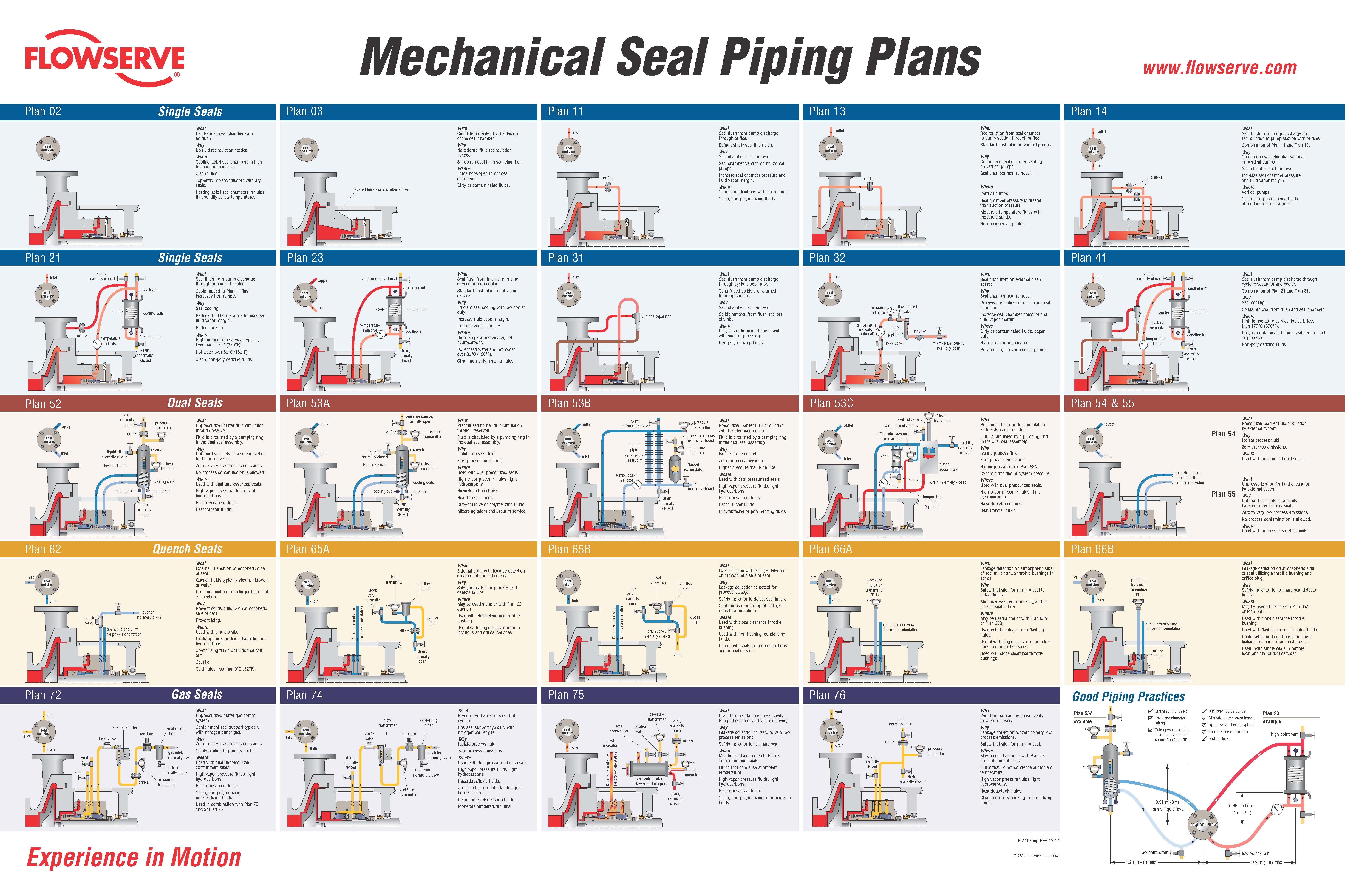
Single Seals plans 01, 02, 03, 11, 13, 14, 21, 23, 31, 32, 41 Dual Seals plans 52, 53A, 53B, 53C, 54, 55 Quench Seals plans 62, 65A, 65B, 66A, 66B Gas Seals plans 72, 74, 75, 76 Mechanical Seal Piping Plans
Flowserve recognizes that one of the most effective ways to achieve long,uninterrupted mechanical seal life is to create a healthy environment aroundthe seal faces. Piping plans help keep mechanical seals running cool andclean, promote safe handling of dangerous fluids, and extend the operationalavailability of rotating equipment. This reference book provides a concisesummary of the most essential piping plans used successfully in today’sprocess plants.
Each plan shows all the standard and optional auxiliary components referencedin API Standard 682 and recommended by Flowserve. Consult your localFlowserve sales engineer to identify the right solution that satisfies yourapplication requirements.Page Layout
Seal End View Piping Plan Layout What, Why, and Where• Viewed from drive end • Illustrated schematic • Describes piping plans, • Shows preferred gland of auxiliary components their purpose, and connection orientation typical applications
What pressure source, Pressurized barrier fluid circulation through reservoir. normally open Fluid is circulated by a pumping ring in the dual seal assembly. outlet pressure Why seal transmitter Isolate process fluid. Zero process emissions. Plan 53A
Plan 53A liquid fill, reservoir Where inlet normally closed Used with dual pressurized seals (”double”). High vapor pressure fluids, light hydrocarbons. level indicator Hazardous/toxic fluids. level transmitter Heat transfer fluids. Dirty/abrasive or polymerizing fluids. cooling coils Mixers/agitators and vacuum service. cooling out cooling in Preventative Maintenance - Reference Appendix B Piping loop must self-vent to reservoir locate at highest elevation. drain, Pressurize reservoir at all times, maximum gas charge 10 - 14 bar (150 - 200 psi). normally Barrier fluid must be compatible with process. closed Reservoir level gage indicates both inboard and outboard seal leakage.
Pump Cross-section Mechanical Seal Preventative Maintenance• Simplified centrifugal • Shows typical seal • Provides general tips to pump shown for all plans arrangements improve reliability and for troubleshooting seal end viewPlan 01
WhatInternal seal chamber flush from pump discharge.Operates similar to Plan 11.WhySeal chamber heat removal.Seal chamber venting on horizontal pumps.
Plan 01Reduce risk of freezing/polymerizing fluid in exposed Plan 11 piping.WhereCustom seal chamber, most likely an ANSI/ASME pump.Clean, moderate temperature fluids.Used with single seals, rarely with dual seals.Preventative MaintenanceFlush typically can not be directed over seal faces and seal heat removal is limited.Calculate flush flow rate based on head loss through internal porting. seal end viewPlan 02 flowserve.com
Plan 02Cooling jacket seal chambers in high temperature services.Clean fluids.Top-entry mixers/agitators with dry seals.Heating jacket seal chambers in fluids that solidify at low temperatures.Preventative MaintenanceProcess must have adequate boiling point margin to avoid vaporization.Cooling fluid in seal chamber jacket may be needed at all times in hot services.Horizontal equipment must be self-venting.Often used in combination with steam quench, Plan 62. seal end viewPlan 03
Plan 03WhereLarge bore/open throat seal chambers.Dirty or contaminated fluids.Preventative MaintenanceProper seal chamber design helps prevent solids from collecting at the seal faces. inlet
Plan 11Seal chamber venting on horizontal pumps.Increase seal chamber pressure and fluid vapor margin.WhereGeneral applications with clean fluids.Clean, non-polymerizing fluids.Preventative MaintenanceUse an orifice with a minimum 3 mm (1/8 inch) diameter.Calculate flow rates to size orifice for adequate seal chamber flow.Increase boiling point margin with proper orifice and throat bushing sizing.Flush should be directed over seal faces with piping at 12 O’clock position.Typical failure mode is a clogged orifice - check temperatures at pipe ends. outlet
WhatRecirculation from seal chamber to pump suction through orifice.Standard flush plan on vertical pumps.WhyContinuous seal chamber venting on vertical pumps.Seal chamber heat removal.
Plan 13WhereVertical pumps.Seal chamber pressure is greater than suction pressure.Moderate temperature fluids with moderate solids.Non-polymerizing fluids.Preventative MaintenanceVent piping loop prior to starting vertical pumps.Use an orifice with a minimum 3 mm (1/8 inch) diameter.Calculate flow rates to size orifice for adequate seal chamber flow.Reduce seal chamber pressure with proper orifice and throat bushing sizing.Typical failure mode is a clogged orifice - check temperatures at pipe ends. outlet
WhatSeal flush from pump discharge and recirculation to pump suction with orifices.Combination of Plan 11 and Plan 13.WhyContinuous seal chamber venting on vertical pumps.Seal chamber heat removal.
Plan 14Increase seal chamber pressure and fluid vapor margin.WhereVertical pumps.Clean, non-polymerizing fluids at moderate temperatures.Preventative MaintenanceUse an orifice with a minimum 3 mm (1/8 inch) diameter.Calculate flow rates to size orifice for adequate seal chamber flow.Increase boiling point margin with proper orifice and throat bushing sizing.Flush should be directed over seal faces.Vent piping loop prior to starting vertical pumps.Typical failure mode is a clogged orifice - check temperatures at pipe ends. vents, normally closed inlet
WhatSeal flush from pump discharge through orifice and cooler.Cooler added to Plan 11 flush increases heat removal.WhySeal cooling.Reduce fluid temperature to increase fluid vapor margin.
Plan 21Reduce coking.WhereHigh temperature service, typically less than 177°C (350°F).Hot water over 80°C (180°F).Clean, non-polymerizing fluids.Preventative MaintenanceSeal cooler and piping must have air vents at highest elevation - vent before starting.When using 682 Seal Cooler, pipe with series flow to maximize heat transfer.Use an orifice with a minimum 3 mm (1/8 inch) diameter.Calculate flow rates to size orifice for adequate seal chamber flow.Increase boiling point margin with proper orifice and throat bushing sizing.Regularly monitor cooler inlet and outlet temperatures for signs of clogging or fouling. vent, normally closed
WhatSeal flush from internal pumping device through cooler.Standard flush plan in hot water services.WhyEfficient seal cooling with low cooler duty.Increase fluid vapor margin.
Plan 23Improve water lubricity.WhereHigh temperature service, hot hydrocarbons.Boiler feed water and hot water over 80°C (180°F).Clean, non-polymerizing fluids.Preventative Maintenance - Reference Appendix ASeal cooler and piping must have air vents at highest elevation - vent before starting.When using 682 Seal Cooler, pipe with parallel flow to minimize head loss.Seal chamber requires close clearance throat bushing to isolate process fluid.Tangential seal gland taps should enter at bottom and exit at top.Regularly monitor cooler inlet and outlet temperatures for signs of clogging or fouling.Process fluids with iron should flow through magnetic separator before cooler. inlet
WhatSeal flush from pump discharge through cyclone separator.Centrifuged solids are returned to pump suction.WhySeal chamber heat removal.Solids removal from flush and seal chamber.
Plan 31WhereDirty or contaminated fluids, water with sand or pipe slag.Non-polymerizing fluids.Preventative MaintenanceCyclone separator works best on solids with a specific gravity twice the process fluid.Seal chamber pressure must be nearly equal to suction pressure for proper flows.Piping should not include an orifice and is not expected to vent the seal chamber.Typical failure mode is clogged separator or pipes - check temperatures at pipe ends. inlet
WhatSeal flush from an external clean source.WhySeal chamber heat removal.Process and solids removal from seal chamber.Increase seal chamber pressure and fluid vapor margin.
WhatSeal flush from pump discharge through cyclone separator and cooler.Combination of Plan 21 and Plan 31.WhySeal cooling.Solids removal from flush and seal chamber.
Plan 41WhereHigh temperature service, typically less than 177°C (350°F).Dirty or contaminated fluids, water with sand or pipe slag.Non-polymerizing fluids.Preventative MaintenanceSeal cooler and piping must have air vents at highest elevation - vent before starting.When using 682 Seal Cooler, pipe with series flow to maximize heat transfer.Cyclone separator works best on solids with a specific gravity twice the process fluid.Seal chamber pressure must be nearly equal to suction pressure for proper flows.Typical failure mode is clogged separator or pipes - check temperatures at pipe ends. vent, normally open pressure outlet transmitter orifice seal end view inlet reservoirPlan 52
WhatUnpressurized buffer fluid circulation through reservoir.Fluid is circulated by a pumping ring in the dual seal assembly.WhyOutboard seal acts as a safety backup to the primary seal.Zero to very low process emissions.
Plan 52No process contamination is allowed.WhereUsed with dual unpressurized seals.High vapor pressure fluids, light hydrocarbons.Hazardous/toxic fluids.Heat transfer fluids.Preventative Maintenance - Reference Appendix BPiping loop must self-vent to vapor recovery/flare system near atmospheric pressure.Process vapor pressure is generally greater than reservoir pressure.Buffer fluid must be compatible with process leakage.Primary seal leakage is indicated by increased vent pressure.Reservoir level indicator shows outboard seal leakage. pressure source, normally open
outlet orifice pressure seal transmitter end view reservoirPlan 53A
WhatPressurized barrier fluid circulation through reservoir.Fluid is circulated by a pumping ring in the dual seal assembly.WhyIsolate process fluid.Zero process emissions.
Plan 53AWhereUsed with dual pressurized seals.High vapor pressure fluids, light hydrocarbons.Hazardous/toxic fluids.Heat transfer fluids.Dirty/abrasive or polymerizing fluids.Mixers/agitators and vacuum service.Preventative Maintenance - Reference Appendix BPiping loop must self-vent to reservoir located at highest elevation.Pressurize reservoir at all times, maximum gas charge 10 - 14 bar (150 - 200 psi).Barrier fluid must be compatible with process.Reservoir level indicator shows both inboard and outboard seal leakage. vent, normally closed pressure outlet transmitter seal pressure source, end view finned pipe normally closedPlan 53B
WhatPressurized barrier fluid circulation with bladder accumulator.Fluid is circulated by a pumping ring in the dual seal assembly.WhyIsolate process fluid.Zero process emissions.
Plan 53BHigher pressure than Plan 53A.WhereUsed with dual pressurized seals.High vapor pressure fluids, light hydrocarbons.Hazardous/toxic fluids.Heat transfer fluids.Dirty/abrasive or polymerizing fluids.Preventative Maintenance - Reference Appendix BPiping loop must be fully vented before starting.Accumulator must be pressurized at all times, usually by gas charge.Barrier fluid must be compatible with process.Regularly monitor barrier pressure - manually add barrier fluid when pressure decays. level indicator level transmitter
outlet vent, normally closed differential pressure seal transmitter liquid fill, end view normallyPlan 53C
WhatPressurized barrier fluid circulation with piston accumulator.Fluid is circulated by a pumping ring in the dual seal assembly.WhyIsolate process fluid.Zero process emissions.
Plan 53CHigher pressure than Plan 53A.Dynamic tracking of system pressure.WhereUsed with dual pressurized seals.High vapor pressure fluids, light hydrocarbons.Hazardous/toxic fluids.Heat transfer fluids.Preventative Maintenance - Reference Appendix BPiping loop must be fully vented before starting.Reference line must tolerate process contamination without plugging.Barrier fluid must be compatible with process.Reservoir level indicator indicates both inboard and outboard seal leakage. outlet
Plan 54WhereUsed with pressurized dual seals.High vapor pressure fluids, light hydrocarbons.Hazardous/toxic fluids.Heat transfer fluids.Dirty/abrasive or polymerizing fluids.Mixers/agitators.Preventative MaintenancePiping loop must be fully vented before starting.Circulating system must be pressurized and energized at all times.Barrier fluid must be compatible with process.Circulating system level indicator shows both inboard and outboard seal leakage. outlet seal end viewPlan 55
WhatUnpressurized buffer fluid circulation by external system.WhyOutboard seal acts as a safety backup to the primary seal.Zero to very low process emissions.No process contamination is allowed.
Plan 55Additional heat removal from the inner seal.Seal cannot induce circulation.WhereUsed with unpressurized dual seals.Hazardous/toxic fluids.Fluids that may solidify in contact with atmosphere.Preventative MaintenancePiping loop must be fully vented before starting .Buffer fluid must be compatible with process leakage.Accumulated process leakage should be routed to a recovery system. inlet seal end viewPlan 62
WhatExternal quench on atmospheric side of seal.Quench fluids typically steam, nitrogen, or water.WhyPrevent solids buildup on atmospheric side of seal.Prevent icing.
Plan 62WhereUsed with single seals.Oxidizing fluids or fluids that coke, hot hydrocarbons.Crystallizing fluids or fluids that salt out.Caustic.Cold fluids less than 0°C (32°F).Preventative MaintenanceQuench inlet should be on top of gland with outlet/drain on bottom.Quench pressure should be limited to 0.2 bar (3 psi) or less.Use throttle bushing on atmospheric side of seal to direct quench flow to seal drain.Monitor regularly, checking for closed valves, blocked lines, and steam trap condition. seal level end view block transmitter valve,Plan 65A
Plan 65AMay be used alone or with Plan 62 quench.Used with close clearance throttle bushing.Useful with single seals in remote locations and critical services.
Preventative MaintenanceDrain must be on bottom of gland with downward-sloped piping.Continuously drain to liquid recovery system.Orifice downstream of level switch transmitter 5 mm (1/4 inch) must be oriented vertically.Bypass line from overflow chamber must re-enter below orifice.Piping may require heat tracing when used with solidifying fluids.Monitor regularly, checking for closed valves, blocked lines, and working level transmitter. seal level end view block transmitter overflowPlan 65B
WhatExternal drain with leakage detection on atmospheric side of seal.WhyLeakage collection to detect for process leakage.Safety indicator to detect seal failure.Continuous monitoring of leakage rates to atmosphere.
Plan 65BWhereUse with close clearance throttle bushing.Use with non-flashing, condensing fluids.Useful with seals in remote locations and critical services.
Preventative MaintenanceDrain must be on bottom of gland with downward sloped piping.Empty collection vessel when level transmitter indicates the vessel is full.Bypass line from collection vessel must re-enter below drain valve.Piping may require heat tracing when used with solidifying fluids.Monitor regularly, checking for closed valves, blocked lines, and working level transmitter. pressure PIT seal indicator end view transmitterPlan 66A
WhatLeakage detection on atmospheric side of seal utilizing two throttle bushings in series.WhySafety indicator for primary seal to detect failure.Minimize leakage from seal gland in case of seal failure.
Plan 66AWhereMay be used alone or with Plan 65A or Plan 65B.Used with flashing or non-flashing fluids.Useful with single seals in remote locations and critical services.Used with close clearance throttle bushings.
Preventative MaintenanceDrain must be on bottom of gland with downward sloped piping.Continuously drain to a liquid recovery system.Monitor for high pressure. pressure PIT seal indicator end view transmitterPlan 66B
Plan 66BMay be used alone or with Plan 65A or Plan 65B.Used with close clearance throttle bushing.Used with flashing or non-flashing fluids.Useful when adding atmospheric side leakage detection to an existing seal.Useful with single seals in remote locations and critical services.
Preventative MaintenanceDrain must be on bottom of gland with downward sloped piping.Continuously drain to a liquid recovery system.Monitor for high pressure.Check orifice regularly for build up and plugging. vent flow coalescing inlet seal filter check transmitter end view regulator valvePlan 72
WhatUnpressurized buffer gas control system.Containment seal support typically with nitrogen buffer gas.WhyZero to very low process emissions.Safety backup to primary seal.
Plan 72WhereUsed with dual unpressurized containment seals.High vapor pressure fluids, light hydrocarbons.Hazardous/toxic fluids.Clean, non-polymerizing, non-oxidizing fluids.Used in combination with Plan 75 and/or Plan 76.Preventative MaintenanceClean, reliable, low pressure gas must be supplied to seal at all times.Bottled gas supply is not recommended except as part of emergency backup system.Primary seal leakage is indicated by pressure in the vent line.Vent or drain are usually connected to low pressure vapor recovery/flare system. inlet flow coalescing seal transmitter filter end view check regulator valvePlan 74
Plan 74WhereUsed with dual pressurized gas seals.High vapor pressure fluids, light hydrocarbons.Hazardous/toxic fluids.Services that do not tolerate liquid barrier seals.Clean, non-polymerizing fluids.Moderate temperature fluids.Preventative MaintenanceClean, reliable, pressurized gas must be supplied to seal at all times.Barrier pressure is typically at least 1.75 bar (25 psig) above seal chamber pressure.Flow indicator shows both inboard and outboard seal leakage.Bottled gas supply is not recommended except as part of emergency backup system. pressure test transmitter connection isolation level valve vent, seal end view indicator normally open orifice
Drain - see end view level transmitter reservoir located below seal drain port
WhatDrain from containment seal cavity to liquid collector and vapor recovery.WhyLeakage collection for zero to very low process emissions.Safety indicator for primary seal.
Plan 75WhereMay be used alone or with Plan 72 on containment seals.Fluids that condense at ambient temperature.High vapor pressure fluids, light hydrocarbons.Hazardous/toxic fluids.Clean, non-polymerizing, non-oxidizing fluids.Preventative MaintenanceCollection reservoir must be located below seal drain and downward-sloped piping.Continuously vent collection reservoir to low pressure vapor recovery/flare system.Drain collection reservoir to liquid recovery system as needed.Primary seal leakage is indicated by increased vent pressure.Monitor regularly for liquid level, valve settings, and low vent pressure. vent vent, normally open seal end viewPlan 76
WhatVent from containment seal cavity to vapor recovery.WhyLeakage collection for zero to very low process emissions.Safety indicator for primary seal.
Plan 76WhereMay be used alone or with Plan 72 on containment seals.Fluids that do not condense at ambient temperature.High vapor pressure fluids, light hydrocarbons.Hazardous/toxic fluids.Clean, non-polymerizing, non-oxidizing fluids.Preventative MaintenanceContinuously vent to low pressure vapor recovery/flare system.Vent piping should include a condensate drain.Primary seal leakage is indicated by increased vent pressure.Monitor regularly for valve settings, blocked lines, and low vent pressure. Single Seals - Plan 23 shown What Minimize restrictions in piping systems high point vent Why Optimum flow rate for best piping plan performance WhereAppendix A
low point Horizontal drain Equipment 0.9 m (3 ft.) maxGood Piping Practices Dual Seals - Plan 53A shown Minimize line losses Use large diameter tubing Only upward sloping lines (slope shall be 40 mm/m [0.5 in/ft]) Use long radius bends
low point Horizontal drain Equipment 1.2 m (4 ft.) max Airfin Coolers TM Seal Cooler 682 Seal Cooler ReservoirsAccessories
Forced air or natural Compact design Seal cooler for General duty and convection seal coolers dual coil seal cooler complete API 682 API 682 compliant specifications reservoirs
Plans 21, 23 & 41 Plans 21, 23 & 41 Plans 21, 23 & 41 Plans 53, 53A & 53B flowserve.com
AccessoriesAccumulator Control Panel Standalone dual seal Mobile cart to manually Complete control support system fill liquid reservoirs system for dual gas seals
Plan 53C Plan 54 Plans 52 & 53 Plans 72 & 74 Seal Gard I & II Orifice Magnetic Separator Cyclone SeparatorAccessories
Combination flush Plug and plate Iron particle separator Solid particle separator flow regulator and style flush line for seal flush used in dirty flush stream meter orifices
Plan 32 Plans 11, 13, 14, & 21 Plan 23 Plans 31 & 41 flowserve.com
Plan 62 Plan 62 modified Plans 52, 53 & 54NotesNotesNotesNotesFTA160eng REV 1-15 Printed in USA USA and Canada To find your local Flowserve representative Kalamazoo, Michigan USA and find out more about Flowserve Corporation Telephone: 1 269 381 2650 visit www.flowserve.com Telefax: 1 269 382 8726


 8613371530291