
3 4 mechanical seal free sample
A dry gas seal is a revolutionary way of sealing machines and protecting them from dust, moisture and other contaminants. A dry gas seal is a sealing device that uses pressurized gas to keep two surfaces from touching. The most common type of dry gas seal is the O-ring, which is used in many applications, including mechanical seals, piston rings, and gaskets. Dry gas seals are also used in many other industries, such as the food and beverage industry, where they are used to seal containers and prevent contamination. This type of seal not only helps to keep the machine running with maximum efficiency but also significantly reduce downtime, making it cost-effective in the long run. In this article, we"ll explore what a dry gas seal is, how it works and why you should consider using it for your machinery. By understanding the benefits of a dry gas seal and its uses, you can make an informed decision about the best sealing system for your needs. How does a dry gas seal work?Dry gas seals work by using a series of labyrinths to separate the high pressure seal gas from the atmosphere. The labyrinths are formed by a series of grooves and ridges on the surface of the seal ring. The seal ring is rotated at high speed, causing the gas to flow through the labyrinths. The gas is then forced through an aperture in the center of the seal ring, where it escapes into the atmosphere. What is a dry gas seal used for?Dry gas seals are used on rotating equipment to help minimize the leakage of high pressure gases from the inside of the machinery. This helps to reduce maintenance costs and improve safety. Dry gas seals are commonly used in applications such as pumps, compressors, turbines, and blowers. Advantages of a dry gas sealThere are many advantages of a dry gas mechanical seal. One advantage is that they are much simpler in design than other types of seals, making them more reliable and easier to maintain. Additionally, dry gas seals do not require the use of any lubricating fluids, which can leak or evaporate over time. This makes them more environmentally friendly and cost-effective in the long run. Finally, dry gas seals have a much longer lifespan than other types of seals, meaning that they need to be replaced less often.Disadvantages of a dry gas sealThere are several disadvantages of dry gas seals, including: - they can be expensive to purchase and install- they require careful maintenance and regular inspection- they can be susceptible to wear and tear- they can leak if not maintained properlyHow to choose the right dry gas seal for your applicationThere are a few key factors to consider when choosing the right dry gas mechanical seal for your application. The most important factor is the type of fluid being sealed. Gas seals are designed to seal either liquids or gases, but not both. Make sure to choose a gas seal that is compatible with the fluid you are sealing.Another important factor to consider is the pressure of the fluid being sealed. Gas seals are rated for different maximum pressures, so make sure to choose one that can handle the pressure of your application.Finally, take into account the size and shape of the sealing surfaces. Gas seals come in a variety of sizes and shapes to fit different applications, so make sure to choose one that will fit your needs.ConclusionDry gas seals are an extremely important component for many industrial operations, and their ability to prevent leaks has made them invaluable in a variety of applications. Understanding the basics of how dry gas mechanical seal work and how they can be used effectively is helpful when considering the various options available for any specific application. With the right choice, dry gas seals can provide reliable, leak-free performance which will save time, money and resources while ensuring safety and reliability. Lepu dry gas seal manufacturer provides best quality flowserve dry gas seal and dry gas seal. Welcome to contact us!
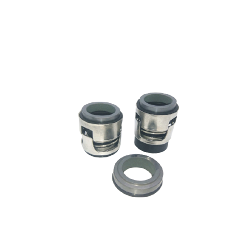
The PSS Shaft Seal is a mechanical face seal. The sealing surface is created between the flat surfaces of the rotating stainless-steel rotor and the stationary carbon flange. The stationary carbon flange is attached to the front side of the bellows with hose clamps, and the back end of the bellows fits over the stern tube and is secured with hose clamps. The stainless-steel rotor is fitted on the shaft in front of the carbon flange. The stainless-steel rotor compresses the bellows before the rotor is secured to the shaft with set screws. This compression (pre-load) maintains constant contact between the two flat faces of the stainless-steel rotor and carbon flange, allowing the PSS to compensate for the variable fore and aft movement due to propeller thrust. In addition, the carbon flange is over-bored to the shaft diameter allowing it to float around the shaft and thus compensate for most misalignment and vibration problems. The stainless-steel rotor is sealed to the shaft by two O-rings recessed into the collar"s bore. These O-rings rotate with the shaft and stainless-steel rotor and do not experience wear during operation.
The global mechanical seals market size stood at USD 3.20 billion in 2018 and is projected to reach USD 4.77 billion by 2026, exhibiting a CAGR of 5.2% during the forecast period.
The key utility of a mechanical seal is to prevent leakage of fluids or gases through the clearance between the shaft and the container. Mechanical seals consist of a set of 2 faces separated by carbon rings. The first face is in contact with the rotating equipment whereas the second face is stationary. Moreover, the main part of the seal is the seal ring (first face) on which the mechanical force is acting, generated by springs, bellows, or fluids in the equipment. In recent years, mechanical seals are playing an important role in varied industrial applications, enabling efficient operations. Mechanical seals are made up of several flexible materials such as Polytetrafluoroethylene (PTFE), Polyurethane (AU, EU), industrial rubber, Fluorosilicone (FVMQ), and many more.
The mechanical seal market has depicted significant growth in the recent span of years and is likely to grow in the forecasted period. Rising industrial development in emerging economies is expected to initiate additional development policies and investments. Major types of mechanical seals available in the market include cartridge seals, balanced and unbalanced seals, pusher and non-pusher, and conventional seals that are influencing the mechanical sealing market growth in developing countries.
Growth in machine tool industry is impelling the overall market share, owing to the usage of power machines in centrifugal pumps and compressors for sealing and separating the fluid in the rotating shafts. Hence, the increasing market demand for mechanical seals in various industries is anticipated to drive the market growth in the near future. Furthermore, the highest market growth is projected to be witnessed in Asia-Pacific, followed by North America.
According to the United Nations Conference on Trade and Development (UNCTAD), the global foreign direct investment (FDI) will grow vigorously in 2018. This implies that there will be strong growth in the manufacturing sector in the coming decade. Moreover, many countries are now adopting investment policies that will boost the manufacturing sector and drive the mechanical seals market trends. For instance, in 2017, several countries and economies adopted investment policy measures across the globe, of which 84% of countries were favorable to investors. This will allow investors to invest their funds in various industries, with primary focus on energy, transportation, and manufacturing.
Therefore, the demand for manufacturing is increasing with the changes in investment policies of multiple developed and developing countries. This growth will increase the adoption of machine tools and industrial equipment for the manufacturing process, which will directly boost the mechanical seals market growth, globally.
The global mechanical seals market is segmented by type, which is further segmented into pusher and non-pusher, conventional seals, balanced and unbalanced seals, and cartridge seals.
Continuous adoption of advanced sealing material in several industries is expected to grow the cartridge seals segment in the forecast period. The cartridge seals segment is estimated to have exponential market opportunities as they are designed as universal shaft seals for the seal chamber of pumps, containers, or pipelines.
The pusher and non-pusher seals segment depicts substantial growth, owing to the increasing usage of small and large diameter ring shaft in the light end services to handle high temperatures. The balanced and unbalanced mechanical seals segment is anticipated to grow moderately, owing to the rise in the industry sector worldwide. Balanced seals are preferred for most of the industrial applications as they generate less heat at the surface of the machine, enabling longer seal life and efficient sealing method.
Comparatively, the conventional seal segment is projected to witness progressive growth owing to the requirement of heat exchanger mating ring advances offered by these seals. The other segment consists of bellows seals and is likely to represent steady growth due to limited demand in the mechanical sealing market.
Oil and gas industry is anticipated to grow exponentially at a higher growth rate owing to increasing demand of petroleum from developed and emerging countries, hence boosting the demand of mechanical seals. Energy utilization is growing worldwide and influencing the demand for electricity generation and consumption rate, thus leading to remarkable market growth. In the current scenario, 70% of the electricity is generated from the renewable sources such as wind and solar power, which bodes well for the mechanical seals market demand.
Mechanical seals demand is increasing in the food and beverage and mining sectors due to increasing implementation of pumps, food tanks, and many other centrifugal machines to manage the intensity of fluid. Marine sector is expected to depict substantial market growth as the need for the mechanical seals at naval ships and ports will remain steady in the forecast period. The others segment consists of chemical industry and is likely to showcase steady growth, owing to minimum demand in the mechanical sealing market.
Asia-Pacific is anticipated to lead the mechanical seals market share and is projected to depict exponential growth over the forecast period due to the increasing industrial applications in the emerging countries including India and China. Along with that, strong economic growth in the manufacturing sector is expected to fuel the development of the market in the region. Furthermore, favorable regulatory framework and regulations by governments for increasing investment in the manufacturing industry is expected to have a substantial impact in the growth of the market. Additionally, rapid industrialization and increasing demand of mechanical seals from industries such as construction, marine, energy and power, and oil and gas is expected to boost the growth of the market. Moreover, the region has several small and medium mechanical seals manufacturers which will increase the market share of the Asia-Pacific region in the forecasted period.
North America is predicted to show a dynamic growth rate over the projected timeline due to the rising number of infrastructure and other development projects in the region, the mechanical seals market analysis points out. This growth in the region is attributed to the presence of key players in the market along with increasing demand for mechanical seals in several industries such as manufacturing, oil & gas, and other mining industries. The growth is owed to deep involvement of workers with technology research and development (R&D) and STEM (science, technology, engineering, and mathematics) in the industries such as energy & power, oil & gas, and aerospace. Furthermore, the demand for the sealing products is accounted for increasing presence of manufacturing industries such as automotive and aerospace to energy industries such as oil and gas extraction to high-tech services such as computer software and computer system design, including health applications.
Furthermore, Europe is witnessing rapid growth owing to rising presence of chemical manufacturing industries along with growing use of sealing products in aerospace, rail, and marine industries. Additionally, demand for sealing products is comparatively stable as the large range of industries in the market offers a relatively balanced market growth over the years. The stability in demand can be seen in the period 2020-2024. Countries such as Italy and Spain are expected to show substantial growth compared to other countries in the region owing to the demand from major industries such as oil & gas and food & beverage.
The mechanical sealing market value in the Middle East and Africa is growing due to presence of more than 65% of global oil refineries in the region. Increasing investment in the oil industry will result in increased demand for mechanical seals. Moreover, countries of the Middle East are shifting their focus from oil and gas production to other industries such as tourism and other manufacturing industries which will result in decreasing market value of mechanical seals.
The manufacturing sector has declined in Latin America over the past few years owing to the decline in the production of cars and other equipment. Moreover, in 2015, the manufacturing production index of Latin America had declined by 0.9%, according to MAPI Foundation. The construction and oil and energy sub-segments are expected to grow at higher rate, owing to the increasing population and demand for the adoption of natural resources. Governments of Brazil, Mexico, and Argentina are working continuously on investing in green energy projects, which in turn will boost the adoption of mechanical seals in several different industries.
SKF (SKF AB), John Crane (Smiths Group Plc.), and Flowserve Corporation are the leading market players. SKF holds the largest market share, as per the mechanical seals market report. This is a result of SKF’s market understanding, along with demand forecasting, which is growing with customer-specific value propositions, giving the company an uptime for designing and production of mechanical seals. This fits with company’s existing engineering skills and asset management approach, with strategic focus on new technology providing value for money and digitalizing of the entire value chain.
Furthermore, John Crane announced that it completed its purchase of the Engineering Division of Advanced Diamond Technologies. The acquisition of ADT will result in enhanced reliability and performance of mechanical seals in key settings in pumps along with other industrial equipment, bringing significant benefits to customers. Also, these strategies offer an enhanced product portfolio to their clients with minimum timelines.
The research report offers an in-depth analysis of the mechanical seals market. It further provides details on the adoption of mechanical seals products across several regions. Information on trends, drivers, opportunities, threats, and restraints of the market can further help stakeholders to gain valuable insights into the market. The report offers a detailed competitive landscape by presenting information on key players, along with their strategies, in the market.
March 2019:John Crane announced its new T4111 cartridge seal. The seal, called the Elastomer Bellows Cartridge Seal, is single-use and is designed to seal rotary and centrifugal pumps, along with similar rotating shaft machines.
April 2019:Dover announced the latest Air Mizer solutions design for the AM Conveyor Equipment Manufacturers Association shaft seal, which is explicitly developed for CEMA equipment & screw conveyors.
March 2018: Hallite Seals continued its third-party authentication with Milwaukee School of Engineering (MSOE) for the reliability & integrity of the design of its seals & sealing materials.
A mechanical seal is simply a method of containing fluid within a vessel (typically pumps, mixers, etc.) where a rotating shaft passes through a stationary housing or occasionally, where the housing rotates around the shaft.
When sealing a centrifugal pump, the challenge is to allow a rotating shaft to enter the ‘wet’ area of the pump, without allowing large volumes of pressurized fluid to escape.
To address this challenge there needs to be a seal between the shaft and the pump housing that can contain the pressure of the process being pumped and withstand the friction caused by the shaft rotating.
Before examining how mechanical seals function it is important to understand other methods of forming this seal. One such method still widely used is Gland Packing.
The stationary part of the seal is fitted to the pump housing with a static seal –this may be sealed with an o-ring or gasket clamped between the stationary part and the pump housing.
The rotary portion of the seal is sealed onto the shaft usually with an O ring. This sealing point can also be regarded as static as this part of the seal rotates with the shaft.
One part of the seal, either to static or rotary portion, is always resiliently mounted and spring loaded to accommodate any small shaft deflections, shaft movement due to bearing tolerances and out-of-perpendicular alignment due to manufacturing tolerances.
The primary seal is essentially a spring loaded vertical bearing - consisting of two extremely flat faces, one fixed, one rotating, running against each other. The seal faces are pushed together using a combination of hydraulic force from the sealed fluid and spring force from the seal design. In this way a seal is formed to prevent process leaking between the rotating (shaft) and stationary areas of the pump.
If the seal faces rotated against each other without some form of lubrication they would wear and quickly fail due to face friction and heat generation. For this reason some form of lubrication is required between the rotary and stationary seal face; this is known as the fluid film
In most mechanical seals the faces are kept lubricated by maintaining a thin film of fluid between the seal faces. This film can either come from the process fluid being pumped or from an external source.
The need for a fluid film between the faces presents a design challenge – allowing sufficient lubricant to flow between the seal faces without the seal leaking an unacceptable amount of process fluid, or allowing contaminants in between the faces that could damage the seal itself.
This is achieved by maintaining a precise gap between the faces that is large enough to allow in a small amounts of clean lubricating liquid but small enough to prevent contaminants from entering the gap between the seal faces.
The gap between the faces on a typical seal is as little as 1 micron – 75 times narrower than a human hair. Because the gap is so tiny, particles that would otherwise damage the seal faces are unable to enter, and the amount of liquid that leaks through this space is so small that it appears as vapor – around ½ a teaspoon a day on a typical application.
This micro-gap is maintained using springs and hydraulic force to push the seal faces together, while the pressure of the liquid between the faces (the fluid film) acts to push them apart.
Without the pressure pushing them apart the two seal faces would be in full contact, this is known as dry running and would lead to rapid seal failure.
Without the process pressure (and the force of the springs) pushing the faces together the seal faces would separate too far, and allow fluid to leak out.
Mechanical seal engineering focuses on increasing the longevity of the primary seal faces by ensuring a high quality of lubricating fluid, and by selecting appropriate seal face materials for the process being pumped.
When we talk about leakage we are referring to visible leakage of the seal. This is because as detailed above, a very thin fluid film holds the two seal faces apart from each other. By maintaining a micro-gap a leak path is created making it impossible for a mechanical seal to be totally leak free. What we can say, however, is that unlike gland packing, the amount of leakage on a mechanical seal should be so low as to be visually undetectable.
The shaft seal is a sealing element which seals the rotating shaft, of a centrifugal pump where it passes through the non-rotating pump casing reducing fluidleakage to atmosphere or the entry of air from outside to a certain level, and keeps wear of the sealing faces as low as possible.
Pumps are specially designed and manufactured to cater for a whole range of different applications. This process takes into account aspects such as resistance to the fluids handled, temperature and pump pressure. The appropriate seal type for the individual pumping requirements is chosen from a wide variety of different shaft seals.
The design is based on one of the two following principles: sealing by means of a narrow radial gap (parallel to the shaft axis) or a narrow axial gap (at a right angle to the shaft axis). For both sealing principles, the gaps may either employ a contact or non-contact design.
If only non-contacting controlled gap seals are used, a considerable amount of leaking fluid can always be assumed. This sealing system is therefore less suitable for environmentally harmful fluids handled.
Shaft seals are by their nature susceptible to leakage, and with some types leakage is actually essential to ensure proper sealing functioning. The suggestion that a seal shaft provides "zero leakage" is therefore misleading. However, depending on the seal type chosen, the amount of leakage
can vary considerably. A volute casing pump with a circumferential speed at the sealing area of 20 m/s and a pressure to be sealed of 15 bar which uses a gland packing for sealing has a leakage rate of about 5 – 8 l/h, while the leakage rate of a mechanical seal used under the same conditions is only approx. 6 cm3/h (0.006 l/h).
The leakage rate of 4 to 6000 l/h for a boiler feed pump sealed by a floating ring seal is particularly high; in this case, the diameter to be sealed is 200 mm and the pressure 40 bar, the
Due to differences in pump designs the individual seal types are not necessarily suitable for every type of application. The type of seal to be employed depends on the sliding velocity, the pressure to be sealed and the fluid temperature.
In the case of contact-type dynamic shaft seals, the parts to be sealed move relative to each other. For this reason lip-contact and line-contact shaft seals (e. g. lip seals) are only suitable for use with very low pressure differences such as those occurring when sealing against bearing oil, and are usually not adjustable.
The packings can be adjusted and are suitable for higher pressures and circumferential speeds than lip seals. Different packing variants are used depending on whether the pump is run in suction head or suction lift operation, or whether it handles clean or contaminated fluid.
As the leakage with gland packings is relatively high compared with mechanical seals, the former are mostly employed for environmentally friendly fluids only.
If the pump is used in suction lift operation, a barrier fluid line and a lantern ring fitted after the first packing ring ensure that air cannot enter via the packing. Provided the pump handles a clean fluid, this barrier fluid is supplied via the pump"s See Fig. 5 Shaft seal
Unlike gland packings, mechanical seals have a sealing gap which is positioned at a right angle to the shaft axis. These shaft seal designs are also called axial or hydrodynamic mechanical seals. Compared with gland packings, they require less space and no maintenance.
Mechanical seals are well-suited for sealing low and high pressures and circumferential speeds. The risk of inappropriate operation is therefore very low.
However, considerable disadvantages arise through wear caused by abrasive fluids (see Abrasion). As is the case with gland packings, clean barrier or flushing fluids (e. g. cleaned by means of cyclone separators) help to keep abrasive particles away from vulnerable seal faces.
Pressed together by hydraulic and mechanicalforces, two seal faces slide relative to each other during operation. The sealing gap lies between these precisely machined seal faces and is filled with a lubricating film, generally a liquid. The sealing gap width (i.e. the distance between both seal faces) is influenced by various factors, including the seal faces" surface quality (i.e. how rough or smooth they are) and the sliding velocity.
Leakage from mechanical seals is very low; the fluid leaks into the atmosphere in the form of vapour or droplets. To calculate the mechanical seal"s leakage rate, a gap width of under 1 μm is normally assumed. Thanks to this extremely narrow gap, the leakage rate for mechanical seals is considerably lower than that for shaft seals with radial gaps.
A further important differentiating feature is that seals can be unbalanced and balanced. In the case of unbalanced mechanical seals, the seal face is exposed to the complete pressure to be sealed.
If the k value becomes smaller, the seal face loads are reduced. For this reason, only balanced mechanical seals are employed in high-pressure and high-velocity applications.
A low k value results in both an improved lubricating film and a higher leakage rate. However, an excessively low k value may in extreme cases cause the complete separation of the seal faces resulting in a loss of the sealing effect.
Alongside the hydraulic closing force, spring forces provide an additional axial force acting on the sealing gap. The springs can employ an open or enclosed design and be in contact with the fluid handled or not; they may or may not transmit torque.
The friction losses generated are lower than those of gland packings. Heat is generated in the shaft seal housing due to friction; depending on the amount produced, it can be dissipated either via convection from the seal housing to the atmosphere or via forced circulation through an externally installed heat exchanger.
Frequently used designsSingle, unbalanced mechanical seal as a typical example for a centrally arranged, conical single spring: The variant shown here is for "dead end" installation, i.e. there is no additional fluid circulation in the mechanical seal area.
Unbalanced mechanical seals are used for pressures of up to max. 15 bar and sliding velocities of up to max. 15 m/s. In general, a sufficient proportion of friction heat generated in the sealing gap can be transferred to the fluid handled and dissipated from the shaft seal housing to the atmosphere via convection. If the fluid handled is cold, the friction heat is absorbed by the fluid itself. One variant is the rubber bellows seal (bellows-type mechanical seal).
Unbalanced mechanical seal with stationary spring assembly: this design is used for higher sliding velocities and ensures the springs can reliably fulfil their task (rotary spring assembly would entail a risk of broken springs due to high centrifugal forces).
Varying spring arrangements are just one example of the distinctive features represented in the wide range of mechanical seal designs tailored for various operating conditions.
In the case of "back-to-back" arrangements, a barrier fluid is fed into the space between the two mechanical seals. Its pressure should be approx. 10 %, and at least 2-3 bar, higher than the pressure of the fluid handled by the pump.
As the barrier fluid absorbs the friction heat generated by the two mechanical seals, it must be circulated, i.e. removed from the seal cavity, cooled and returned to the seals.
The barrier fluid pressure is generated by a barrier fluid system (thermosyphon vessel) or pressure booster. In the case of tandem seals, the space between the seals is flushed by unpressurised quench liquid (quench). If the leaking fluid handled by the pump has a tendency to crystallise when in contact with air, a seal arrangement comprising two rubber bellows seals should be used. It is important that the quench liquid and fluid handled are compatible.
Instead of using an outboard mechanical seal, it is also possible to install a simple sealing element such as a lip seal or packing ring. It is fitted as a back-up seal for the main seal to prevent leakage (e. g. in the case of hazardous fluids) and to safely and reliably dissipate heat.
Tandem seals are employed when a high internal pump pressure requires distribution to two mechanical seals. The barrier fluid pressure level then lies between the pressure to be sealed and the atmospheric pressure. The pressure handled by the inboard seal corresponds to the difference between the pressure to be sealed and the barrier fluid pressure; the pressure handled by the outboard seal corresponds to the difference between the barrier fluid pressure and the atmospheric pressure. The barrier fluid must circulate in order to dissipate the friction heat generated by the seals.
These mechanical seal types are used in the boiling or pressurised water reactors of nuclear power stations and are installed in main coolant pumps to seal extremely high pressures.
The pressure must be distributed via an auxiliary system, e.g. a three-stage cascading system of throttles arranged in the seals" bypass lines. A defined amount of water flows via the bypass line. Pressure is thus reduced by approx. 33 % at each throttle. The reduced pressure at each stage"s output is the operating pressure for the next stage"s input. This throttling and recirculation of the barrier fluid ensures the pressure is reduced and the friction heat removed from the sealing stages.
In the case of boiler feed pumps, seals have to cope with high sliding velocities, heat transfer from the fluid handled and the heat generated by friction.
The sealing gap temperature is generally higher than the fluid temperature in the seal housing. The latter can be kept well below 100 °C by circulating the fluid through to an external cooler by means of suitable pumping devices inside the pump. Pumping screws, holes in the shaft protecting sleeve or small pumping discs serve as pumping devices.
Detrimental dry running of the mechanical seal may occur if the pump is operated without liquid fill and in the event of a major ingress of gas, a high gas content or the evaporation of the fluid handled. Due to its low density, the gas always tends to move to smaller diameters which is the sealing gap of seals in most cases. The presence of air in this space leads to dry running and also impedes sufficient heat dissipation from the sealing gap resulting in thermal overload of the seal faces and mechanical seal failure (heat stress cracks) within a very short time.
External cooling circuits are not used if the heat losses generated by the seal can be dissipated to the atmosphere via free convection and heat radiation.
Other forms of cooling comprise a fan impeller mounted to the pump shaft to intensify convection (forced convection). In both cases the seal housing is provided with fins, at a right angle to the shaft axis (without fan impeller) see Fig. 16 Shaft Seal, and parallel to the shaft axis (with fan impeller).
In the case of uncooled mechanical seals operated at high temperatures, the temperature in the sealing gap is generally higher than the temperatures in the sealing gaps described so far. This means that the boundary between the liquid and vapour phase in the sealing gap inevitably shifts towards the sealing gap inlet, increasing the risk of insufficient lubrication.
The sealing gap width between the stationary component and the rotating component is designed to be as narrow as possible in order to minimise leakage. However, it is important to ensure that the parts do no rub against each other. Leakage on a rotating shaft is slightly lower than during standstill.
The fluid flowing through the gap allows the pressure to be reduced in relation to the atmospheric pressure. On throttling gaps and floating ring seals this is achieved in the gap due to fluid friction and due to flow losses when the fluid enters or leaves the gap.
Floating ring sealThe major advantage of floating ring seals is the fact that the components are not in contact. However, the time and costs required to provide the barrier condensate, its treatment and relevant control equipment are substantial.
The floating ring seal consists of several short throttling rings fitted in succession which can move in a radial direction and centre themselves automatically due to the pressure distribution on the ring. A cold barrier condensate injected into the seal ensures that hot water from the pump does not escape to the atmosphere (controlled system). As long as the pump is in operation or under pressure, barrier water supply must be ensured.
The floating ring seal is occasionally employed in boiler feed pumps. Its barrier condensate quantity can be controlled via the barrier condensate"s pressure and temperature difference.
Labyrinth sealThe labyrinth seal is a firm throttling bush with a circular groove profile. As radial movement is impossible with this type of seal, the diametral clearance must be wider
Centrifugal sealThis type of shaft seal generates pressure itself in order to counteract the differential pressure to be sealed; it is frequently backed up by a standstill seal. Designed as
spring-loaded mechanical seal, it is opened by centrifugal forces at very low speeds and thus protected against wear. See Fig. 20 Shaft sealThe actual centrifugal seal (fitted as an auxiliary impeller using a liquid ring at the outer diameter) operates contact- and wear-free.
Hydrostatic sealDue its design, proper functioning of the hydrostatic seal as a non-contact seal is only ensured at pressures from 20 bar. The pump drive must not be started until this pressure level is reached.
The gap"s stiffness is very high at full operating pressure (160 bar). To move the gap from its balanced position by 1 μm, an external force of approx. 4000 N would be
The gap with which the seal operates may be very narrow, but it is finite, and as such exhibits a considerable leakage rate (p = 160 = 160 bar, n = 1.500 = 1500 rpm; sealing diameter at 260 mm, Q = 800 = 800 l/h). It is therefore necessary to back up the hydrostatic seal with a low-pressure seal that provides sealing to atmosphere.
See Fig. 22 Shaft sealDue to the hydrostatic seals’ operating limitation at low pressures, they have been replaced with hydrodynamic mechanical seals in many nuclear power stations.
Static contact seals include O-rings. These are moulded seals and are defined as "rings with circular cross section made of elastic materials; they seal through the effect of slight bracing during installation, intensified by the operating pressure" according to DIN 3750. Their symmetrical cross-section rules out incorrect installation.
O-rings are employed on all the shaft seals described here. However, they can only be used as static sealing elements or to seal areas where slight axial movement is occasionally required.
The majority of O-rings used on mechanical seals are elastomer rings with a shore A hardness of 70 to 90. These O-rings are used for sealing between the shaft sleeves and the shaft, and between the primary ring or the mating ring and the respective components they are connected with. They ensure that the spring-loaded seal component can follow small axial shaft movements.
Their significance is often underestimated: ultimately, each shaft seal is only as good as its O-ring. O-rings must be matched to the fluid handled, cover a defined temperature range and provide good ageing resistance. Moreover, it is important to use a high-quality O-ring grease which meets the operating requirements. Besides providing long-term lubrication, the grease must be compatible with the fluid handled and must not attack the O-ring.
Elastomers which swell less than 10 % in the operating fluid and do not chemically react with the fluid handled are suitable for use as a mechanical seal"s secondary seal. A number of elastomers are available for this purpose which react differently in a reference oil with regard to temperature


 8613371530291