
api 610 mechanical seal code factory
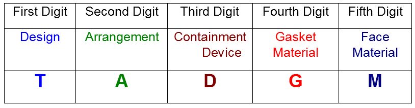
A seal code is an abbreviated method of communicating basic specifications for the mechanical seal. Sadly, the seal code has been changed with every edition of API 682. Fortunately, the new code, described in API 682 4th Edition Annex D, is the best to date and includes some concepts and codes from the historical API 610 seal code. The new code uses eight fields:
API 682 4th Edition was the first edition to include materials in the description and in many ways represents a combination of API 682 coding and the old API 610 codes.
4th Edition coding comprises four sections, some being sub-divided. The table below shows the construction of a typical seal code, it is intended to accurately describe the seal and seal system being implemented in a given application.
T: Seal type A, B or C per API 682 4th Edition definitions. For dual seals using different inner and outer seal types, show both types using the format inner/outer.
Note that the codes used for Design Options are the same as those used in API 610 for materials that are included in both systems. On the other hand, some materials cannot be specified because API 682 does not recommend them. Such materials must be specified with an “X”.
For many years the pump standard API 610 contained a mechanical seal coding system which became widely used in industry. This coding method provided a reference to the nomenclature and features used with mechanical seals that were current during that time period. While this coding method is obsolete it still is still being used in some areas of industry. It is presented herein as a historical reference only.
A very commonly used code was BSTFM which translates to a balanced single seal with throttle bushing in the gland plate. Gaskets would be FKM (fluoroelastomer). Seal faces would be carbon vs nickel bound tungsten carbide.

T - Seal gland type (P = plain, no throttle bushing; T = throttle bushing with quench, leakage and/or drain connections; A = auxilary sealing device, type to be specified) Note: See 2.7.3.21

P = plain, without throttle bush T = throttle bush with quench, leakage and / or drainage connection A = additional/ auxiliary seal (has to be stated)
4th letterstationary seal ring gasket, seal ring to sleeve gasket 5th letter --- ring 1 means seal ring ,ring 2 means mating seal ring Note seal ring ---seal face
Example for sealing and material code: BSTFO = balanced, single-acting mechanical seal with throttle bush, with dynamic and static secondary seals (O-rings) made of FKM and seal faces/ secondary seats made of tungsten carbide against silicon carbide

Please contact AESSEAL Systems Division for further details. Tel: +44 (0)28 9266 9966 Email: systems@aesseal.com For more information, and a video demonstrating the piping plan in operation, select a plan below

BSTFO = balanced, single-acting mechanical seal with throttle bush, with dynamic and static secondary seals (O-rings) made of FKM and seal faces/ secondary seats made of tungsten carbide against silicon carbide
Safety tandem mechanical seal, specifically suited for sealing of easy inflammable or spontaneously inflammable media, light hydrocarbons, LPG/ liquid gas, solvents and similar media in connection with flare; also for low temperature applications.
Special seal face geometry as well as use of excl. solid seal face/ stationary seats combine to form mechanical seal with lowest level of seal face distortion when exposed to compressive load and thermic pressure - leading to higher safety of operation and improved service life.
As double-acting mechanical seal in back-to-back arrangement available: style 851BOperation: API plan 53 (higher barrier fluid pressure) with adequate auxiliary equipment (supervision of measured values recommended) specifically suited for:
The refinery seal for "hot" pumps, for sealing of hot-oils, for hot cracking products with catalyzer, in FCC plants and others (acc. to use of adequate auxiliary equipment)
API 682 specifies cartridge (cartridge preassembled) mechanical seals, as well as dynamic test runs for all types of mechanical seals and arrangements with defined conditions.
35 m/sspecifically difficult environment, such as: solid material, frequent changing of operating conditions; mechanical seal with double pressure balance

Whenever a new edition of global specifications [e.g., International Organization for Standardization (ISO) and the American Petroleum Institute (API)] is released, there is usually massive confusion surrounding understanding explicit details of the key changes and why they were made. This article addresses five areas of changes that deal directly with pump reliability and maintainability, along with highlighting other various changes incorporated in API Standard 610 12th Edition, Centrifugal Pumps for Petroleum, Petrochemical and Natural Gas Industries, published in January 2021.
Background.API documents are typically updated on a 5-yr interval. API 610 12th Edition had a release date of January 2021, close to 11 yr after the published 11th Edition, primarily due to key items which required some additional time to resolve. The API 610 taskforce began working on this update in 2006. The group addressed the latest developments for rotating equipment, reliability issues, industry issues and proposed changes based upon proven, sound engineering and operating practices. Collaboration with other industry groups such as the Hydraulic Institute, the International Electrotechnical Commission (IEC), the National Electrical Manufacturers Association (NEMA) and ASTM ensured that this document reflected their latest updates. It should be noted that the API 610 12th Edition standard is no longer co-branded with ISO. The 9th, 10th and 11th Editions of API 610 were co-branded as ISO 13709.
The time required for the pump manufacturing industry to incorporate the changes to API 610 in the 12th Edition into their pump designs is difficult to determine. Historically, previous editions of API 610 have transitioned into worldwide usage over about a 2-yr period. Engineers generally will embrace certain changes to API 610 12th Edition because of the benefits presented by these changes, especially regarding the impact on pump reliability. The rest of this article highlights key changes in the standard, with some background explanations.
The annex contains sections for definition; selection criteria for pressure boundary and rotor; design considerations for pressure boundary components, impellers, diffusers or volutes, shaft seals, bearings and bearing housings; materials; manufacturing; and testing guidelines. Product reliability and maintainability is critical for these high-energy pumps. Examples of special purpose pumps are:
For high-energy pumps, every aspect of the design requires careful review, including rotor stiffness, distribution of residual stresses in metal-to-metal sealing surfaces, determination of deflection at critical fits and the establishment of proper running clearances. Performing structural analysis of impellers and diffusers (or volutes) is essential as is determining the proper net positive suction head (NPSH) margin based upon incipient NPSH (NPSHi), not just the generic 3% NPSH3. Especially for new designs, finite element analysis (FEA) of the bearing housing should be done to carefully determine the types of bearings to use. Lastly, the ability to easily assemble and disassemble impellers must be taken into consideration. As for manufacturing requirements, patterns and rigging should provide sound castings while non-destructive testing of highly stressed areas should be performed.
Introduction of API RP 691 Risk Based Machinery Management.API 610 12th Edition now refers to API RP 691—Risk-based Machinery Management—by means of bulleted paragraphs whereby the purchaser needs to advise the vendor when this recommended practice document is invoked. API 691 defines technical readiness levels (TRL) for machinery, with TRLs ranging from conceptual, prototype equipment (TRL 0) to well established, field-proven machinery (TRL 7). When API RP 691 is invoked, the vendor is to advise the purchaser of the TRL of the equipment being offered. API 691 defines high-risk machinery as machinery that handles hazardous liquids or gases, services operating at temperatures of more than 177oC (350oF) and operating pressures of more than 80% of maximum allowable working pressure (MAWP), services operating at temperatures of more than 204oC (400oF), components with TRLs less than 7, liquid services operating at pressures higher than 41.4 bar (600 psig), and liquid services with specific gravity less than 0.5.
API 610 11th Edition required a 20-yr minimum service life. This requirement was replaced in the 12th Edition with requiring only “field proven” equipment to be consistent with other API standards and with the API standard paragraphs. This eliminated any inferred equipment warranty issues.
For several past API 610 editions, a continuous rising to shut-off head curve was mandatory for all pumps. The 12th Edition changed this to be a bullet item for customers to select when they want rising-to-shut-off head curves. However, a note in this bullet paragraph clearly states, “pumps with continuously rising head curve are preferred for all applications, but this is not possible with all pump types.” An example of this is low-specific speed pumps (typically low-flow/high-head, high speed pumps, which have slightly drooping curve shapes, and pumps with multiple radial blade (Barske) design impellers. For pumps operating in parallel, in addition to a minimum 10% rise-to-shut-off mandate, the 12th Edition requires pumps with discharge nozzles larger than 3 in. (80mm) within the preferred operating flow region, to have head values within 3% of each other. These stipulations ensure one pump will not “push” the second pump to shut-off.
Important changes to the API 610 data sheets were made to address all alternate hydraulic operating points: rated and normal (same as before); however, now three additional operating points for customers to advise. These could be for handling a different liquid (as typically found with pipeline pumps or tank farms) or even liquids used to flush pumps during maintenance periods. Most important is that the driver (usually electric motor) is selected to handle the power requirements to handle all these operating conditions, which may have large differences in specific gravity causing an increase in Kw (Hp). Besides data sheets, the 12th Edition introduces a data list, which includes all data found on the data sheets; however, in a tabular form to compile all data into a neutral format to support electronic data exchange (EDE) among contractor, end user and pump manufacturer to minimize possible errors in transposing numbers among all parties.
Pipeline services are characteristic of pumping products with lower product temperatures vs. medium to hot temperature liquids found in refinery services. Because of this, API 610 12th Edition now states the limit for using sleeve/sleeve-ball bearings in pipeline pumps as 8 × 10⁶ kW/min (10.7 × 10⁶ hp/min) after which hydrodynamic radial and thrust bearings are to be used. The 12th Edition also states that for pipeline pumps, with energy density values between 4 × 10⁶ kW/min (5.4 × 10⁶ hp/min) and 8 × 10⁶ kW/min (10.7 × 10⁶ hp/min), hydrodynamic radial bearings shall be used with either rolling-element or hydrodynamic thrust bearings.
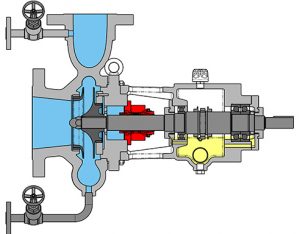
New to the 12th Edition is the mandate for shaft guards. Previous API 610 editions, including the 11th Edition, addressed only coupling guards. Inputs from multiple refineries indicated that safety organizations were pointing out that the area between the pump casing cover and the bearing housing has an exposed shaft area that should be covered (FIG. 2). More specifically, this is the shaft area where the mechanical seal gland is located. Furthermore, the drive collar adjacent to the cartridge seal has set screws, which could be a concern if someone placed their hand in that area during pump operation. Basic design for refineries addresses venting to prevent accumulation of seal emissions and a port to measure emissions, whereas for pipeline services a different approach is typically taken.
Options for other designs such as open top-plate, non-grouted and non-grouted with gimble mounts are addressed. The purchaser is to advise which design is required. Designation for Annex D, which provides pre-engineered baseplate sizes, has changed from being normative to informative based on the industry feedback that with today’s enhanced computerized layout of equipment by engineering, procurement and construction (EPC) companies and the quick turnaround by vendors to generate pump general arrangement drawings, this mandate for standardized baseplate sizes has diminished. The 12th Edition states baseplates may have Annex D dimensions if driver, pump size, auxiliaries and seal flush piping properly fit.
A new requirement for OH2 pumps addresses the location for placing auxiliaries in the front region (adjacent to pump suction nozzle area) of the baseplate. This is a major change that improves accessibility for maintenance of single-stage overhung pumps by preventing blocking of the area adjacent to the pump bearing housing, mechanical seal, and coupling and providing easy access to remove the coupling and back-pull-out assembly (including bearing housing and case cover with mechanical seal) for maintenance. This is particularly important for OH2 process pumps with seal reservoirs for Plan 52, 53 and control panels for non-contacting gas seals, along with seal flush plans with coolers such as Plan 23 (FIG. 3). For between bearing pumps, auxiliaries are preferred to be mounted on one side leaving the other side open for easy maintenance.
Definitions, pump pressure ratings.As part of the review process for producing the 12th Edition, Standard Paragraphs—which apply to all rotating equipment—were reviewed. They were compared to the 11th Edition to determine where possible changes in definitions would be required. The definitions needing attention were MAWPand maximum discharge pressure. In both cases, these pressures are now based on maximum specific gravity, and it is the responsibility of the customer to provide this information on the improved format of the API data sheets.
The 11th Edition (as well as all previous API 610 editions) required that OH, BB1 and BB2 pumps be rated for 41 bar (600 psi). The 11th Edition had a special note stating that by the time the 12th Edition is issued, OH, BB1 and BB2 pumps would be required to have a pressure rating equal to that of a PN 40. (300 lb) flange, which is 51 bar (740 psi) at 100°F (38°C). Further discussions revealed that most of these pump sizes generate heads that are relatively low. This translates to the current 41 bar (600 psi) pressure requirement to which most pump manufacturers comply. The final decision was made to revert to the 40 bar (600 psi) rating for these pump types. It should be noted that most manufacturers do have, as an option, higher pressure pump designs, especially for high suction pressure applications which require PN 100. (600 lb), PN 160. (900 lb) and even PN 250. (1500 lb) flanges and heavier wall thickness casing designs.
Explanation has been added to address disassembly after performance testing of BB3 and BB5 pumps to ensure that all water is removed from internal passageways, as water cannot be removed simply by draining for these designs. However, for these multistage pumps, pump disassembly after tests may be invasive to the point of impacting mechanical integrity.
Improved wording and images, diagrams and normative references.One of the main objectives for the API 610 12th Edition task force was to improve wording throughout the document for clarity to assist international users. With this goal in mind, images and diagrams were added to show requirements more explicitly (e.g., baseplate designs), along with expanding the table of contents to include figures and tables, and adding a listing of acronyms and abbreviations
Similarly, a better description of single-stage axial split between bearings BB1 pump classification—foot- or near-centerline-mounted—was added to BB3 and BB4 pumps. “Centerline supported” was added to BB2 pumps. A further clarification was made so that the figures shown generically represent the various pump types and do not reflect actual construction details or certain pump features. This wording was added to help both contractors and end users apply variations of the images without concern. FIG. 6 depicts two additional nozzle orientations for BB1 pumps. FIG. 7 shows a typical top/top nozzle orientation for OH2 single-stage overhung process pumps. This combination was very common in the past, as it provided a cleaner field piping arrangement without typical end suction pump piping obstruction at the ground level, and for modular design systems where space is a premium. These orientations are still purchased today and are not considered as deviations or exceptions to API 610 12th Edition.
Takeaway.This article has touched on the main and other changes from API 610 11th Edition to the 12th Edition. Most of them have impacted pump reliability and maintainability. Changes were made to reflect industry feedback and most end user specification requirements to elevate equipment to a level of minimizing the need of overlay specifications. However, as technology changes and more demanding services arise, the API 610 standard continues to evolve.
Frank Korkowski (korkowskifrancis@gmail.com) is the Manager of Engineered Training at Applied K3nowedge Consulting. He is a consultant recently retired from Flowserve and previously was theMarketingManager for the API 1 and 2 stage process pumps. He spent 45yrin various pump roles with Ingersoll Rand, Ingersoll-Dresser Pumps and Flowserve.Mr. Korkowski earned a BS degree in industrial engineering fromthe New Jersey Institute of Technology,with post-graduate studies in engineering and business administration at Lafayette College and Fairleigh Dickinson University.
Tom Hess (thess@e2g.com) is the Principal Rotating Engineerfor The Equity Engineering Group, Inc. Prior to joining Equity, Mr. Hess worked as aRotatingReliabilityEngineer in an oil refinery.Hehas been fascinated with sealless pumps fornearly30yr. Heearnedhis BSME from Villanova University, is a member of ASME and is a registered professional engineer in the Commonwealth of Pennsylvania. Mr. Hess is a member of the API 685, 610, 682 and 613 Task Forces.
Roger L. Jones (rogerjonessping@aol.com) is a Rotating Equipment Consultant and Task Force Chairmanfor API 610. Mr. Jones spent 32yrin various positions at different Shell companies. In his career,he has held numerous technical and managerial positions in chemical plants and refineries, major capital projects and engineering consulting roles.He earned BS and MS degrees in mechanical engineering from Kansas State University and is a registered professional engineer in Texas. He is the previous chairman of the International Standards Coordinating Committee of the API and head of the U.S. delegation to the various ISO technical committees governing standards for refining and offshore equipment. He is a former member of the International Pump Users Symposium Advisory Committee.

API (American Petroleum Institute) is a set of standards used to define systems, tests, and equipment design, mainly in the Oil & Gas industry. There are other standards, such as ISO, ASME, NEMA, or ANSI. Although these standards may be referred to alongside API, they are not otherwise related, and although some of these standards overlap, each one is generally focused on a different sector.
API standards include design criteria for a wide range of equipment and components. Power Zone is involved daily with the API standards relating to pumps and pump components, as well as API guidelines for pump testing and API design criteria for pump baseplate design.
Even though there is no overall rule or law that API standards must be adhered to (many pumps and equipment are built to no standard at all) the API standard is often referred to in pumping systems when the highest quality is needed.
API 610 is the API standard relating specifically to centrifugal pumps and centrifugal pumping systems. It provides design criteria for the design of the actual centrifugal pump, as well as how the centrifugal pump is to be tested, and what type of base it is to be mounted on.
Within the API 610 Centrifugal Pump Standard, there are various configuration codes for different types of centrifugal pumps. These are called out by a set of two letters followed by a single number. The letters are used to define the main different pump types, where OH stands for Overhung, BB stands for Between-bearings, and VS stands for Vertically Suspended. The number is used to differentiate more detailed configuration options within each section.
The API OH1 is a horizontal, foot mounted, single stage, overhung pump with end suction. The pump is mounted to a baseplate and driven via a flexible coupler.
The API OH2 is a horizontal, centerline mounted, single stage, overhung pump with end suction, and a single bearing housing. The single bearing housing helps absorb the forces imposed on the pump shaft and maintain the position of the rotor during pump operation.
The API OH3 is a vertical inline, single stage, overhung pump with separate bearing brackets. The bearing housing is integral with the pump to help absorb the loads imposed on the pump, and the motor is generally mounted on a support that is also integrated with the pump. The pump and motor are coupled with a flexible shaft coupling.
The API OH4 pump is a vertical inline, single stage, overhung pump with a rigid coupling on the pump and motor shafts. The C-face of the motor is mounted directly to the pump housing.
The API OH5 pump is a vertical inline, single stage, overhung pump that is close-coupled with the motor. In the close-coupled design, the pump impeller is mounted directly to the motor shaft (the motor shaft is designed to be extra-long), and the C-face of the motor is mounted directly to the pump housing.
The API OH6 is a horizontal or vertical, single-stage, overhung, high-speed pump that has an integral gearbox mounted to the pump housing. The gearbox is driven by the motor with a flexible coupling, and the pump impeller is mounted directly to the high-speed shaft of the gearbox.
API 674 is the API standard relating to reciprocating positive displacement pumps and includes design criteria for both direct acting reciprocating pumps and power-frame type pumps (pumps driven by a motor via a crankshaft). The standard defines topics such as maximum and minimum speeds, pulsation and vibration control requirements, and testing requirements.
The mechanical seal is the most likely part of the pump to fail. Approximately 70% of the pumps removed from service for maintenance are victims of mechanical seal failure. Mechanical seal parts are highly engineered with very close tolerances and any upset in the pump or associated system can cause seal failure, including:
Mechanical seals are based on positioning two very flat and smooth discs called seal faces, one rotating on the shaft, and one stationary in the pump, against each other. The discs are flat and smooth enough to ALMOST prevent the pumped fluid from leaking out between them. However, the faces do rely on a very thin film of fluid between the faces to lubricate that rubbing fit. Without this film of fluid, the seals will overheat and fail. Lack of lubrication is the PRIMARY cause of seal failure.
If the fluid is very hot, it can flash to vapor as the fluid moves across the faces, again resulting in a lack of lubrication. Note that gas seals use a gas film between the faces to minimize face contact and heat buildup.
Seal flush plans are intended to keep the area around the seal in the most seal friendly environment practical, usually meaning clean and cool. Dual seal plans also provide backup and leak detection for safety.
Note that seal flush plans use pressure differences at the pump to drive the flush fluids. The pump suction is low pressure, the seal chamber is a medium pressure, and the pump discharge is at high pressure.
As the seal faces rub together (with their thin film of lubricating fluid), they generate heat. The heat can build up in the seal chamber and push the fluid towards its boiling point, resulting in premature flashing, lack of lubrication, and failure. This first set of seal plans is intended to create circulation through the seal chamber to dissipate the heat out of the seal chamber and back into the pumped fluid.
Flush fluid flows from high pressure at pump discharge to the medium pressure seal chamber and back into the main flow to remove heat from the seal chamber
Can be used to increase the seal chamber pressure. The increased chamber pressure may be required to keep chamber fluid from flashing to vapor or to provide enough pressure to push the fluid between the faces for lubrication. (Seal chamber must be 5 psi minimum above external atmospheric pressure)
These seal plans are intended to provide the seal with the friendliest environment possible by cooling and/or cleaning the fluid in the seal chamber. The throat that separates the seal chamber from the main pumped fluid can be further restricted by adding a close clearance bushing in the bottom of the seal chamber, better isolating the cool, clean seal chamber fluid from the hot, abrasive fluid in the pump.
Rather than a Plan 21 single-pass system, a Plan 23 is a multi-pass system. Fluid comes FROM THE SEAL CHAMBER instead of the pump discharge is cooled, and directed back to the seal chamber
Fluid is driven out of the chamber and through the cooler by a “pumping ring” or other “pumping feature” built into the seal. These features provide very little differential pressure. Connecting tubing must have long, sweeping bends, well vented high points, and low point blowouts to ensure fluid flows
Quench piping does NOT change conditions inside the seal chamber, on the wet side of the seal faces. Rather, it affects or monitors the environment on the ATMOSPHERIC side of the seal faces.
Pumps that leak when they are filled, even before they are started, often have a flush line intended for a Plan 11 or 13 connected to the QUENCH port, leading to the atmospheric side of the seal. There should be a “Q” or the work “QUENCH” stamped in the gland at this port.
For flush plans Plan 65A, 65B, 66A, and 66B, facility owners may want to know if their seals are leaking excessively without going to the expense of dual seals. These seal plans direct excessive leakage on the outside of the seal to an alarm instrument. Remember that seals leak a little bit. They need to in order to lubricate the faces and function correctly. The plans below handle the nuisance leakage in different ways.
Used in salting services like sodium hydroxide. The leakage across the seal faces will turn to salt when it reaches atmosphere. The salt crystals can wear the faces or build up in the seal, preventing the movement necessary to keep the seal faces in contact. The salt on the outboard of the seal can be washed away with a water quench through the quench and drain ports. Usually, a close clearance bushing is installed at the extreme outboard end to the seal assembly to help keep the quench fluid moving from the quench to the drain port (or vice versa) and not just run out along the shaft. Also used for slurry services
Grease can be introduced into the quench port. This external grease can provide temporary lubrication to the seal in case the pump sees large air or vapor pockets which would normally rob the seal faces of the required lubricating fluid film
Quench can also be gas. In hot hydrocarbon services, the fluid will turn to solid coke when it reaches the atmospheric side of the seal. The fluid would remain a liquid if the area outside the seal faces is robbed of oxygen with a flood of nitrogen or steam
An alarm does NOT necessarily mean a failed seal. The collection vessel might be full from years of nuisance leakage. Try emptying the vessel and observing how fast the vessel fills
Two throttle bushings are used to ensure that the vapor (or fluid) leakage is limited along the shaft and out of the drain. A pressure switch picks up a rise in pressure above nuisance levels on the outboard side of the seal
Dual seals provide a backup seal in case the primary seal fails. They prevent hazardous fluids from leaking to the surrounding area, desirable for both environmental protection and the safety of nearby personnel.
Dual seals also capture and control any leakage of pumpage across the primary seal. The backup seal is kept lubricated by introducing a buffer/barrier fluid (often a mineral or synthetic oil, a water/glycol mix, or diesel) into the space between the primary (inboard) and secondary (outboard or backup) seals. The buffer/barrier fluid is contained in a tank (5 gallons is most common) adjacent to the pump. The instrumentation on the tank indicates what is happening with the seals.
Remember that a lubricating fluid film will flow from high pressure to low pressure. If the pump seal chamber pressure is higher than the pressure on the other side of the seal, the pumpage will be the lubricating film. If the pump’s seal chamber pressure is lower than the external pressure, the external atmosphere will migrate into the pump.
Pumps under vacuum cannot use an ordinary single seal, since air from the atmosphere would be drawn between the faces, causing them to run dry and fail. Using a dual seal allows fluid to be present at the outside of the seal. In a pump under vacuum, the buffer fluid would be pulled into the pump between the seal faces, keeping the inboard seal well lubricated.
If the pump seal chamber pressure is higher than the BUFFER fluid between the primary and backup seal faces, then the pumped fluid will flow from the high seal chamber pressure into the low-pressure buffer fluid. This is called a DUAL UNPRESSURIZED seal (formerly called a tandem seal), and the fluid is called a BUFFER fluid.
If the pump seal chamber pressure is lower than the BARRIER fluid between the primary and backup seal faces, then the barrier fluid will flow across the primary seal from the space between the primary and backup seals into the pump. This is called a DUAL PRESSURIZED seal (formerly called a double seal), and the fluid is called a BARRIER fluid.
Buffer fluid circulates from the buffer fluid reservoir, through the space between the primary and backup seal, and back to the reservoir. The fluid is circulated by a weak pumping action built into the seal
If the fluid flashes to vapor at low pressure, the vapor is piped to a flare or vapor recovery system, through an orifice at the top of the tank. If the primary seal is allowing too much leakage, the vapor will build pressure in the reservoir against the orifice and a pressure instrument can alert the operator
If the fluid remains as a liquid under low pressure, any leakage will cause the fluid level in the buffer tank to rise, where a high-level alarm can be tripped. Just because the high-level alarm is tripped does not mean that the primary seal is failing; it is the rate of leakage filling the tank which matters. The high level may have been reached after collecting years of nuisance leakage. Often, an oil change to the original level is all that is required. Be sure the fluid is disposed of properly
Seal face friction or hot pumpage can add heat to the buffer fluid. A cooling water coil is often installed in the reservoir to cool the buffer fluid
Dual pressurized system (seal barrier fluid is at a higher pressure than the pump seal chamber). Pressurized systems are used to ensure that very dangerous fluids remain in the pump. The difference between 53A, 53B, and 53C is the method of pressurizing the barrier fluid. Pressure in the barrier fluid should be at least 10 psi over the pressure in the pump seal chamber.
Barrier fluid circulates from the barrier fluid reservoir, through the space between the primary and backup seal, and back to the reservoir. The fluid is circulated by a weak pumping action built into the seal
A low-level alarm in the reservoir alerts the operator that a seal may be failing, allowing the barrier fluid to enter the pump through the primary seal or the atmosphere through the backup seal
Seal faces can be designed to maintain a gas film between them rather than a fluid film. These piping plans are intended to work with theses gas film (dry running) seals. Plan 72 and 74 bring the buffer or barrier gas into the seal; plans 75 and 76 are for the gas exiting the seal.
The secondary seal is ordinarily running with a gas film between the faces. When the primary seal fails, the pumped fluid will fill the space between the primary and backup seal. The backup seal is now working as a liquid seal rather than a gas seal and is designed to run for about 8 hours, allowing the operators time for an orderly pump shutdown.
Plan 72 buffer gas flow keeps the gas in the seal from becoming concentrated from nuisance leakage over time so that any leakage from the gas backup seal is mostly inert flush gas and not toxic pump vapors
Pumping processes involving toxic or hazardous fluids that can’t risk leakage because of stringent environmental regulations require a double mechanical seal. Compared to a single mechanical seal, a double seal gives you significantly greater protection against leaks. With a double mechanical seal, you have an arrangement of two mechanical seals (a primary or inboard seal and a secondary or outboard seal) in series—back-to-back, tandem, or face-to-face. Each seal has a rotating (R) surface and a stationary (S) seal surface. These seals can be arranged in one of three patterns.
In a back-to-back arrangement, the stationary seal faces are positioned back-to-back with the rotating seal faces on the outside. The back-to-back arrangement is easy to install and used for many general pumping applications.
The tandem arrangement has the two pairs of seals mounted with the same orientation. This arrangement is preferred for toxic or hazardous applications because the outboard seal provides full pressure back-up, allowing the outboard seal to back up in the event of an inboard seal failure.
In the face-to-face arrangement, the rotating seal faces share a common stationary seal face. This arrangement is useful when equipment space is too constrained to permit back-to-back or tandem seal arrangements.
The American Petroleum Institute (API) Standard 682 classifies double mechanical seals into two configurations—pressurized and unpressurized. The pressurized arrangement has a barrier fluid delivered to the double mechanical seal by a seal support system. The barrier fluid is delivered at a higher pressure than the process fluid and must be chemically compatible with the process fluid as it will lubricate the inboard seal faces and mix with the process fluid. The unpressurized arrangement has a buffer fluid delivered to the double mechanical seal by a seal support system. The buffer fluid is delivered at a lower pressure than the process fluid.
The barrier and buffer fluids you use can be liquid or gas. They provide lubrication and help maintain the required operating temperature of the seal faces. The typical choices are water and water/glycol mixtures, low-viscosity petroleum or synthetic oils, kerosene, diesel, and nitrogen.
To gain a better understanding of the differences between the uses of barrier and buffer fluids, let’s look at two common API plans for double mechanical seals—API Plan 52 Buffer Fluid Seal Pot and API Plan 53A Barrier Fluid Seal Pot Pressurized by Nitrogen.
API Plan 52 takes buffer (unpressurized) fluid from a reservoir (seal pot), delivers it to the seal chamber, circulates it between the inboard and outboard seals using a pumping ring located driven by shaft rotation, then returns the fluid to the reservoir. In the event of an inboard seal failure, process fluid leaks into the seal chamber. When that occurs an increase in buffer fluid pressure and/or level alerts operators to the problem. The outboard seal, however, contains leakage until maintenance can replace the damaged seal.
This plan can include cooling coils in the reservoir to maintain the required buffer fluid temperature, visual or mechanical fluid level indicators, pressure and level transmitters, and connection to a collection system and buffer fluid replenishment source.
The overall design of this API plan for a double mechanical seal is relatively simple in comparison to other plans. Design decisions involving tubing size, length, geometry, type (carbon vs stainless steel), buffer fluid type, and volume of the buffer fluid reservoir are critical in maintaining the proper operating environment for the double seal. If you don’t have this expertise in-house, work with an experienced, local seal support system vendor to ensure the API Plan 52 is designed to meet your specific pumping requirements.
API Plan 53A is conceptually similar to API Plan 52 with the difference that the fluid being circulated between the double mechanical seals is under pressure. A pumping ring is used to circulate the fluid. The reservoir that contains the barrier fluid is pressurized by plant nitrogen. Reservoir pressure should be set a minimum of 20 to 25 psi (1.4 to 1.73 bar) above the maximum seal chamber pressure, allowing the barrier fluid to leak (and lubricate) across the inboard seal faces into the process fluid. For this reason, the barrier fluid must be chemically compatible with the process fluid.
Because barrier fluid is depleted as it moves across the inboard seal faces, it needs to be replenished. This can be done manually or automatically by way of a system that serves multiple pumps. API Plan 53A design options include reservoir type and volume, cooling coils, fluid level and pressure indicators, and transmitters to alert to level or pressure changes that indicate seal failure.
When you choose an API plan for a double mechanical seal, your primary decision is between a buffer or barrier plan. I’ve highlighted two of the API plans for double mechanical seals above to show the basic differences. There are multiple API plans for double mechanical seals to choose from—pressurization from bladder or piston accumulators, plant nitrogen delivered directly to the seal chamber, and custom-engineered external systems. Your choice will be determined by the process fluid and pumping conditions and the type of double mechanical seal your vendor recommends.
With this information in hand, it’s best to work with an experienced local seal support system vendor. They’ll be able to meet with you on-site to review the specifications for the pumping process, the pump, and the double mechanical seal. They’ll evaluate your existing infrastructure and its influence on seal support system design. Based on this information, they’ll then design the seal support system to meet the specific pumping requirements.
If you work with a global vendor like Swagelok, based on the design, we can quickly assemble and thoroughly test the API plan at our local facilities prior to delivery. We’re also conveniently available for follow-up consultations, on-site, remotely, or by way of a quick phone call.
For well over 50 years, Swagelok has worked closely with Northern California process industries to confidently choose the right API plans for pumping needs. Our locally based Field Engineers and certified technicians provide field verification of your seal support requirements, designs based on best practices gained from global experience.
To find out more about howSwagelok Northern California can help you choose the right API plan for double mechanical seals, as well as process and atmospheric side seals,contact our team today by calling
Morgan holds a B.S. in Mechanical Engineering from the University of California at Santa Barbara. He is certified in Section IX, Grab Sample Panel Configuration, and Mechanical Efficiency Program Specification (API 682). He is also well-versed in B31.3 Process Piping Code. Before joining Swagelok Northern California, he was a Manufacturing Engineer at Sierra Instruments, primarily focused on capillary thermal meters for the semiconductor industry (ASML).


 8613371530291