
api plan 52 mechanical seal brands
Depressurised buffer fluid circulation in outboard seal of a dual seal configuration through a seal support system. Circulation is maintained by using pumping ring in running condition and by thermosyphon effect in stand still condition.
1. Keep the sealant vessel vent continuously open, which is necessary to maintain buffer fluid pressure close to atmospheric pressure and vent the vapors to flare.
Circulation of buffer liquid to and from the reservoir is dependent on thermal siphoning and/or an internal circulating device (pumping ring) inside the seal.
The MP52 series aligns with API 682 Plans 52 and 53A. The Plan 52 is designed to support liquid buffer fluid for a containment seal chamber that is below the seal chamber pressure. The Plan 53A is a pressurized system designed to isolate the seal from the process completely by providing liquid barrier fluid at a pressure higher than the seal chamber.
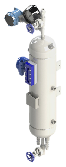
Our seal reservoirs are built to ASME Section VIII standards and are available with ASME U code stamps. Flexaseal Engineered Seals and Systems, LLC provides standard and custom buffer fluid reservoirs that meet API 682 Standards. As an industrial seal pot manufacturer for the chemical, petrochemical, and industrial industries, our seal pot systems help protect the environment and your workers from hazardous materials.
![]()
Pumping processes involving toxic or hazardous fluids that can’t risk leakage because of stringent environmental regulations require a double mechanical seal. Compared to a single mechanical seal, a double seal gives you significantly greater protection against leaks. With a double mechanical seal, you have an arrangement of two mechanical seals (a primary or inboard seal and a secondary or outboard seal) in series—back-to-back, tandem, or face-to-face. Each seal has a rotating (R) surface and a stationary (S) seal surface. These seals can be arranged in one of three patterns.
In a back-to-back arrangement, the stationary seal faces are positioned back-to-back with the rotating seal faces on the outside. The back-to-back arrangement is easy to install and used for many general pumping applications.
The tandem arrangement has the two pairs of seals mounted with the same orientation. This arrangement is preferred for toxic or hazardous applications because the outboard seal provides full pressure back-up, allowing the outboard seal to back up in the event of an inboard seal failure.
In the face-to-face arrangement, the rotating seal faces share a common stationary seal face. This arrangement is useful when equipment space is too constrained to permit back-to-back or tandem seal arrangements.
The American Petroleum Institute (API) Standard 682 classifies double mechanical seals into two configurations—pressurized and unpressurized. The pressurized arrangement has a barrier fluid delivered to the double mechanical seal by a seal support system. The barrier fluid is delivered at a higher pressure than the process fluid and must be chemically compatible with the process fluid as it will lubricate the inboard seal faces and mix with the process fluid. The unpressurized arrangement has a buffer fluid delivered to the double mechanical seal by a seal support system. The buffer fluid is delivered at a lower pressure than the process fluid.
The barrier and buffer fluids you use can be liquid or gas. They provide lubrication and help maintain the required operating temperature of the seal faces. The typical choices are water and water/glycol mixtures, low-viscosity petroleum or synthetic oils, kerosene, diesel, and nitrogen.
To gain a better understanding of the differences between the uses of barrier and buffer fluids, let’s look at two common API plans for double mechanical seals—API Plan 52 Buffer Fluid Seal Pot and API Plan 53A Barrier Fluid Seal Pot Pressurized by Nitrogen.
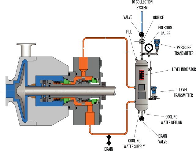
API Plan 52 takes buffer (unpressurized) fluid from a reservoir (seal pot), delivers it to the seal chamber, circulates it between the inboard and outboard seals using a pumping ring located driven by shaft rotation, then returns the fluid to the reservoir. In the event of an inboard seal failure, process fluid leaks into the seal chamber. When that occurs an increase in buffer fluid pressure and/or level alerts operators to the problem. The outboard seal, however, contains leakage until maintenance can replace the damaged seal.
This plan can include cooling coils in the reservoir to maintain the required buffer fluid temperature, visual or mechanical fluid level indicators, pressure and level transmitters, and connection to a collection system and buffer fluid replenishment source.
The overall design of this API plan for a double mechanical seal is relatively simple in comparison to other plans. Design decisions involving tubing size, length, geometry, type (carbon vs stainless steel), buffer fluid type, and volume of the buffer fluid reservoir are critical in maintaining the proper operating environment for the double seal. If you don’t have this expertise in-house, work with an experienced, local seal support system vendor to ensure the API Plan 52 is designed to meet your specific pumping requirements.
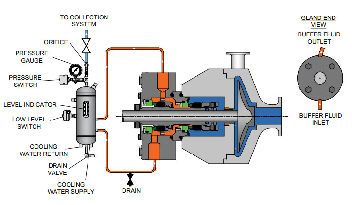
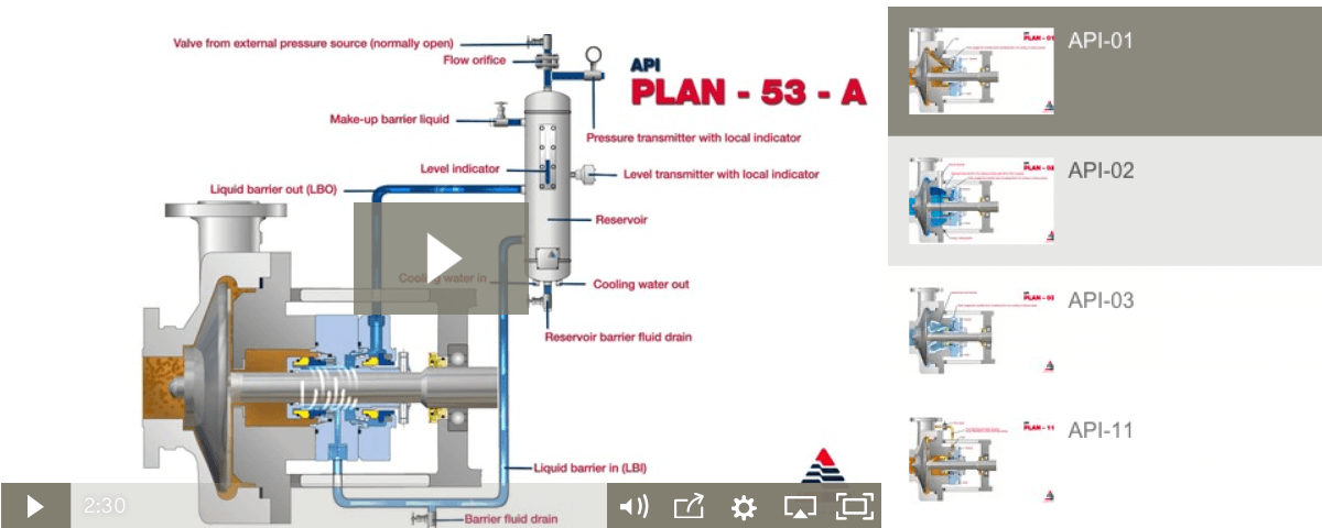
API Plan 53A is conceptually similar to API Plan 52 with the difference that the fluid being circulated between the double mechanical seals is under pressure. A pumping ring is used to circulate the fluid. The reservoir that contains the barrier fluid is pressurized by plant nitrogen. Reservoir pressure should be set a minimum of 20 to 25 psi (1.4 to 1.73 bar) above the maximum seal chamber pressure, allowing the barrier fluid to leak (and lubricate) across the inboard seal faces into the process fluid. For this reason, the barrier fluid must be chemically compatible with the process fluid.
Because barrier fluid is depleted as it moves across the inboard seal faces, it needs to be replenished. This can be done manually or automatically by way of a system that serves multiple pumps. API Plan 53A design options include reservoir type and volume, cooling coils, fluid level and pressure indicators, and transmitters to alert to level or pressure changes that indicate seal failure.
When you choose an API plan for a double mechanical seal, your primary decision is between a buffer or barrier plan. I’ve highlighted two of the API plans for double mechanical seals above to show the basic differences. There are multiple API plans for double mechanical seals to choose from—pressurization from bladder or piston accumulators, plant nitrogen delivered directly to the seal chamber, and custom-engineered external systems. Your choice will be determined by the process fluid and pumping conditions and the type of double mechanical seal your vendor recommends.
With this information in hand, it’s best to work with an experienced local seal support system vendor. They’ll be able to meet with you on-site to review the specifications for the pumping process, the pump, and the double mechanical seal. They’ll evaluate your existing infrastructure and its influence on seal support system design. Based on this information, they’ll then design the seal support system to meet the specific pumping requirements.
If you work with a global vendor like Swagelok, based on the design, we can quickly assemble and thoroughly test the API plan at our local facilities prior to delivery. We’re also conveniently available for follow-up consultations, on-site, remotely, or by way of a quick phone call.
For well over 50 years, Swagelok has worked closely with Northern California process industries to confidently choose the right API plans for pumping needs. Our locally based Field Engineers and certified technicians provide field verification of your seal support requirements, designs based on best practices gained from global experience.
To find out more about howSwagelok Northern California can help you choose the right API plan for double mechanical seals, as well as process and atmospheric side seals,contact our team today by calling
Morgan holds a B.S. in Mechanical Engineering from the University of California at Santa Barbara. He is certified in Section IX, Grab Sample Panel Configuration, and Mechanical Efficiency Program Specification (API 682). He is also well-versed in B31.3 Process Piping Code. Before joining Swagelok Northern California, he was a Manufacturing Engineer at Sierra Instruments, primarily focused on capillary thermal meters for the semiconductor industry (ASML).

Flowway Teknik design and manufactures seals and associated products mainly for the oil and gas, chemical, pharmaceutical, pulp and paper, power, mining and many more industrial applications. Today, it provides the most complete selection of engineered mechanical seals and sealing support systems. Our products are recognized as a trusted brand in a process industry.

In the past there was only one Plan 53, but with the 2nd Edition of API 682 and the 1st Edition of ISO 21049 other variations of Plan 53"s were created.
Plan 53A is the former Plan 53. Plan 53B is what had been in the past denoted as Plan 53 Modified; this is especially popular in European and other countries in the Middle East. Plan 53C is a variation of this that has also been used in the past and is now formally recognized.
The major difference in the plans is that Plan 53A uses an external reservoir, while Plans 53B and 53C run within a closed loop system with a make-up system piped to it for replenishment of the barrier fluid.
In dual pressurized sealing arrangements the inner process seal can have its own flush plan; in such applications the complete flush plan system designation should include both plans. For example, Plan 11/53A means that the inner seal has its own flush plan, Plan 11. The API/ISO default is for no separate flush plan when using any of the Plan 53"s, but this can vary with the application conditions.
With the older traditional back-to-back seal arrangement the inboard seal usually does not require a separate flush. In applications such a hydrofluoric acid, where it is both extremely hazardous and corrosive, a Plan 32 can be used in conjunction with a Plan 53. The dual pressurized face-to-back seal arrangement eliminates some of the potential problems associated with the back-to-back design. This face-to-back seal arrangement sometimes incorporates a reverse pressure capability that is not a default with the back-to-back design.
Also, face-to-back arrangements do not have a dead zone underneath the inboard seal that can become clogged by dirty process fluid and lead to seal hang-up. However, the face-to-back arrangement is not a cure-all. With the product on the seal O.D. and with it being used on API pumps that still incorporate throat bushings, it is advantageous to provide a flush for the inboard seal on a number of applications.
Abrasives can accumulate in the more closed API type seal chambers compared to the newer generation chemical duty pumps with large cylindrical bore or tapered bore chambers. The use of a Plan 11 or similar bypass type flush for the inner seal has advantages. It can help keep the seal chamber clean. It also has an improved overall heat transfer setup versus just using a Plan 53 system alone.
In comparison to a Plan 54, Plans 53A/B/C are usually less complex and less expensive. With Plans 53A/B/C, both the inner and the outer seals are lubricated by the barrier fluid, which can be selected for optimum seal performance. Plans 53A/B/C are usually selected for dirty, abrasive, or polymerizing process services which might be difficult to seal directly with single seals or with dual unpressurized seals using a Plan 52. There will always be some leakage of the barrier fluid into the process with any pressurized system.
With some of the Plan 53 systems the volume of barrier fluid is limited, especially compared to a Plan 54 system. Venting of the seal chamber is essential for all Plan 53"s where vapor locking can if vapor bubbles collect near the pumping ring or in the piping.
Plan 53A uses an external reservoir to provide barrier fluid for a pressurized dual seal arrangement. Reservoir pressure is produced by a gas, usually nitrogen, at a pressure greater than the maximum process pressure being sealed. The gas pressure is regulated by a system that is outside the schematic of the piping plan. Circulation of the barrier fluid is maintained by an internal pumping ring.
Like Plan 52 reservoirs, cooling is accomplished internal coil of tubing to remove the heat. Also like Plan 52 reservoirs, the volume of barrier liquid can vary from two gallons to 5+ gallons, where API and ISO standards specify 3-gal and 5-gal, depending upon the shaft diameter.
For non-API specifications, smaller reservoirs - typically 2-gal - are often used, especially at ambient pumping temperatures. Pressure alarms, pressure gages and level switches are typically standard equipment and are required by API 682/ISO 21049.
The usual guideline for Plan 53 barrier pressures is that they be a minimum of 20-psi to 50-psi above the maximum process pressure seen by the seal. Barrier pressure is normally supplied by a plant wide distribution system. Nitrogen bottles should not be used as they require a lot of attention and maintenance.
API 682/ISO 21049 recommends that the system be limited to 150-psig due to gas entrainment into the barrier fluid. Field experience has shown that with the proper barrier fluid, Plan 53A systems can be used up to 300-psig if the temperature is controlled to less than 250-deg F. A variation to this would be to use an accumulator to eliminate gas entrainment.
Disadvantages (vs. other Plan 53 systems)The barrier fluid in Plan 53A is subject to gas entrainment due to direct exposure to the pressurizing gas. Different barrier fluids have varying levels of gas entrainment.
Installation should be limited to a single seal installation even on between bearing pumps. Therefore for a large number of installations, Plan 53A can be more expensive than Plan 53B or 53C.
nlike a Plan 53A that incorporates a pressurized reservoir within the circulation loop, Plan 53B incorporates a bladder type accumulator along with the piping and an air or water cooled heat exchanger to provide for barrier fluid capacity.
Some installations use finned tubing as the heat exchanger, but these should be used with caution as the heat removal depends upon a positive air flow across the tubing to be effective. Gas entrainment is not a problem with this plan since it incorporates bladder accumulator to maintain the barrier pressure within the closed loop circuit.
The accumulator should be pre-pressurized to between 80 percent and 90 percent of the barrier pressure. This creates a problem in that it limits the volume of fluid within the Plan 53B circuit. The majority of the accumulator volume is gas. The basic setup is comprised of two parts; the closed loop circulating system made up of the piping and heat exchanger and the make up system.
Flow in the circulating system is usually induced by an internal pumping device. The make up system can be configured a number of ways based upon the customer"s preference, ranging from a simple hand pump to an elaborate pumping system feeding multiple pumps/seals.
Like Plan 53A, the flow rate of the Plan 53B circuit is controlled by the pumping ring design, peripheral speed, barrier fluid viscosity, and resistance of the piping circuit; the piping circuit of 53B includes a heat exchanger. The sizing of the heat exchanger depends upon the heat load of the system. The heat exchanger should be designed to contribute minimum resistance.
API 682, 3rd edition does not provide guidelines for sizing the accumulator of Plan 53B, but the total fluid volume of the system should be about the same as the volume of a 53A system.
Disadvantages (vs. other Plan 53 systems)The volume of fluid within the closed loop circuit is very limited, as little as one-half gallon in some instances.
With the limited fluid volume the barrier fluid gets thermally cycled on a much more frequent basis than a Plan 53A, so the service life of the fluid is reduced.
The finite volume of the accumulator requires a designed pressure operating range between refills (in excess of that required for a Plan 53A) and this must be built into the pressure rating of the seals.
The separate heat exchanger introduces additional flow resistance to the piping system and will have a lower flow rate than an otherwise identical Plan 53A.
Plan 53C is a variation of Plan 53B that uses a piston accumulator to track the pressure of the seal chamber. In Plan 53C, the piston accumulator has a reference line from the seal chamber to the bottom of the accumulator. There are differences in diameter of the internal piston so that a higher pressure is generated on the top half, which in turn is piped to the circuit loop into and out of the seal chamber.
Similar to Plan 53B, there is no gas pressurizing the barrier fluid so there is no chance of gas entrainment. Also, like Plan 53B flow is generated by a pumping ring through a heat exchanger. The heat exchanger can be water cooled, air cooled or can be finned tubing if the heat load is small enough. This system should be used with caution, as the reference line to the accumulator is subject to the process fluid. The process fluid may be corrosive, abrasive, or a slurry that could potentially clog the pressure reference line threatening the tracking ability of the system.
The advantages and disadvantages are the same as the Plan 53B system. Additionally, the disadvantage of this system is that pressure spikes or pressure drops in the process pressure will vary the pressure on the outer seal that may create a temporary leakage condition. Also, tracking pressures can always be subject to delays that can cause a temporary loss of positive pressure differential across the inboard seal.
PHOTO : https://www.eagleburgmann.com/media/literature-competences-products-solutions/division-mechanical-seals/competences/brochure-barrier-buffer-media-for-mechanical-seals
The mechanical seal is the most likely part of the pump to fail. Approximately 70% of the pumps removed from service for maintenance are victims of mechanical seal failure. Mechanical seal parts are highly engineered with very close tolerances and any upset in the pump or associated system can cause seal failure, including:
Mechanical seals are based on positioning two very flat and smooth discs called seal faces, one rotating on the shaft and one stationary in the pump, against each other. The discs are flat and smooth enough to ALMOST prevent the pumped fluid from leaking out between them. However, the faces do rely on a very thin film of fluid between the faces to lubricate that rubbing fit. Without this film of fluid, the seals will overheat and fail. Lack of lubrication is the PRIMARY cause of seal failure. If the fluid is very hot, it can flash to a vapor as the fluid moves across the faces, again resulting in lack of lubrication. Note that gas seals use a gas film between the faces to minimize face contact and heat buildup.
Seal flush plans are intended to keep the area around the seal in the most seal friendly environment practical, usually meaning clean and cool. Dual seal plans also provide backup and leak detection for safety.
Note that seal flush plans use pressure differences at the pump to drive the flush fluids. The pump suction is low pressure, the seal chamber is a medium pressure, and the pump discharge is at high pressure.
As the seal faces faces rub together (with their thin film of lubricating fluid), they generate heat. The heat can build up in the seal chamber and push the fluid towards its boiling point, resulting in premature flashing, lack of lubrication, and failure. This first set of seal plans is intended to create circulation through the seal chamber to dissipate the heat out of the seal chamber and back into the pumped fluid.
Flush fluid flows from high pressure at pump discharge to the medium pressure seal chamber and back into the main flow to remove heat from seal chamber
Can be used to increase seal chamber pressure. Increased chamber pressure may be required to keep chamber fluid from flashing to vapor or to provide enough pressure to push the fluid between the faces for lubrication. (Seal chamber must be 5 psi minimum above external atmospheric pressure).
These seal plans are intended to provide the seal with the friendliest environment possible by cooling and/or cleaning the fluid in the seal chamber. The throat that separates the seal chamber from the main pumped fluid can be further restricted by adding a close clearance bushing in the bottom of the seal chamber, better isolating the cool, clean seal chamber fluid from the hot, abrasive fluid in the pump.
Rather than a Plan 21 single pass system, a Plan 23 is a multi-pass system. Fluid comes FROM THE SEAL CHAMBER instead of the pump discharge, is cooled, and directed back to the seal chamber.
Fluid is driven out of the chamber and through the cooler by “pumping ring” or other “pumping feature” built into the seal. These features provide very little differential pressure. Connecting tubing must have long, sweeping bends, well vented high points, and low point blowouts to ensure fluid flows.
Quench piping does NOT change conditions inside the seal chamber, at the wet side of the seal faces. Rather, it affects or monitors the environment on the ATMOSHPERIC side of the seal faces.
Pumps that leak when they are filled, even before they are started, often have a flush line intended for a Plan 11 or 13 connected to the QUENCH port, leading to the atmospheric side of the seal. There should be a “Q” or the work “QUENCH” stamped in the gland at this port.
For flush plans Plan 65A, 65B, 66A, and 66B, facility owners may want to know if their seals are leaking excessively without going to the expense of dual seals. These seal plans direct excessive leakage on the outside of the seal to an alarm instrument. Remember that seals leak a little bit. They need to in order to lubricate the faces and function correctly. The plans below handle the nuisance leakage in different ways.
Used in salting services like sodium hydroxide. The leakage across the seal faces will turn to salt when it reaches atmosphere. The salt crystals can wear the faces or build up in the seal, preventing the movement necessary to keep the seal faces in contact. The salt on the outboard of the seal can be washed away with a water quench through the quench and drain ports. Usually a close clearance bushing is installed at the extreme outboard end to the seal assembly to help keep the quench fluid moving from the quench to the drain port (or vice versa) and not just run out along the shaft. Also used for slurry services.
Grease can be introduced into the quench port. This external grease can provide temporary lubrication to the seal in case the pump sees large air or vapor pockets which would normally rob the seal faces of the required lubricating fluid film.
Quench can also be gas. In hot hydrocarbon services, the fluid will turn to solid coke when it reaches the atmospheric side of the seal. The fluid would remain a liquid if the area outside the seal faces is robbed of oxygen with a flood of nitrogen or steam.
An alarm does NOT necessarily mean a failed seal. The collection vessel might be full from years of nuisance leakage. Try emptying the vessel and observing how fast the vessel fills.
Two throttle bushings are used to ensure that the vapor (or fluid) leakage is limited along the shaft and out of the drain. A pressure switch picks up a rise on pressure above nuisance levels on the outboard side of the seal.
Dual seals provide a backup seal in case the primary seal fails. They prevent hazardous fluids from leaking to the surrounding area, desirable for both environmental protection and the safety of nearby personnel. Dual seals also capture and control any leakage of pumpage across the primary seal. The backup seal is kept lubricated by introducing a buffer/barrier fluid (often a mineral or synthetic oil, a water/glycol mix, or diesel) into the space between the primary (inboard) and secondary (outboard or backup) seals. The buffer/barrier fluid is contained in a tank (5 gallons is most common) adjacent to the pump. Instrumentation on the tank indicates what is happening with the seals.
Remember that a lubricating fluid film will flow from high pressure to low pressure. If the pump seal chamber pressure is higher than the pressure on the other side of the seal, the pumpage will be the lubricating film. If the pump’s seal chamber pressure is lower than the external pressure, the external atmosphere will migrate into the pump. Pumps under vacuum cannot use an ordinary single seal, since air from the atmosphere would be drawn between the faces, causing them to run dry and fail. Using a dual seal allows a fluid to be present at the outside of the seal. In a pump under vacuum, the buffer fluid would be pulled into the pump between the seal faces, keeping the inboard seal well lubricated.
If the pump seal chamber pressure is higher than the BUFFER fluid between the primary and backup seal faces, then the pumped fluid will flow from the high seal chamber pressure into the low pressure buffer fluid. This is called a DUAL UNPRESSURIZEDseal (formerly called a tandem seal), and the fluid is called a BUFFER fluid.
If the pump seal chamber pressure is lower than the BARRIER fluid between the primary and backup seal faces, then the barrier fluid will flow across the primary seal from the space between the primary and backup seals into the pump. This is called a DUAL PRESSURIZEDseal (formerly called a double seal), and the fluid is called a BARRIER fluid.
Buffer fluid circulates from the buffer fluid reservoir, through the space between the primary and backup seal, and back to the reservoir. Fluid is circulated by a weak pumping action built into the seal.
It the fluid flashes to vapor at low pressure, the vapor is piped to a flare or vapor recovery system, through an orifice at the top of the tank. If the primary seal is allowing too much leakage, the vapor will build pressure in the reservoir against the orifice and a pressure instrument can alert the operator.
If the fluid remains as a liquid under low pressure, any leakage will cause the fluid level in the buffer tank to rise, where a high level alarm can be tripped. Just because the high level alarm is tripped does not mean that the primary seal is failing; it is the rate of leakage filling the tank which matters. The high level may have been reached after collecting years of nuisance leakage. Often, an oil change to the original level is all that is required. Be sure the fluid is disposed of properly.
Seal face friction or hot pumpage can add heat to the buffer fluid. A cooling water coil is often installed in the reservoir to cool the buffer fluid.
Dual pressurized system (seal barrier fluid is at a higher pressure than the pump seal chamber). Pressurized systems are used to ensure that very dangerous fluids remain in the pump. The difference between 53A, 53B, and 53C is the method of pressurizing the barrier fluid. Pressure in the barrier fluid should be at least 10 psi over the pressure in the pump seal chamber.
Barrier fluid circulates from the barrier fluid reservoir, through the space between the primary and backup seal, and back to the reservoir. Fluid is circulated by a weak pumping action built into the seal.
A low level alarm in the reservoir alerts the operator that a seal may be failing, allowing the barrier fluid to enter the pump through the primary seal or the atmosphere through the backup seal.
Seal faces can be designed to maintain a gas film between them rather than a fluid film. These piping plans are intended to work with theses gas film (dry running) seals. Plan 72 and 74 bring the buffer or barrier gas into the seal; plans 75 and 76 are for the gas exiting the seal.
Secondary seal is ordinarily running with a gas film between the faces. When the primary seal fails, the pumped fluid will fill the space between the primary and backup seal. The backup seal is now working as a liquid seal rather than a gas seal and is designed to run for about 8 hours, allowing the operators time for an orderly pump shutdown.
Plan 72 buffer gas flow keeps the gas in the seal from becoming concentrated from nuisance leakage over time so that any leakage from the gas backup seal is mostly inert flush gas and not toxic pump vapors.

Cyclone separators are typically used in an API Plan 31 arrangement and incorporated in the seal flush line (API Plan 11 ) from the discharge of the pump.
53B accumulator-based seal support systems utilize a bladder to maintain system pressure to pressurized dual seals and absorb barrier fluid thermal expansion while separating the pressurizing gas and barrier fluid.
53C accumulator-based seal support systems utilize a piston to maintain system pressure to pressurized dual seals and absorb barrier fluid thermal expansion while separating the pressurizing gas and barrier fluid.
Used to detect and monitor leakage of the inboard seal, these seal support systems can detect liquid leakage (API Plans 65 and 75) or gas leakage (API Plan 76), or a mixture of gas and liquid leakage (API Plan 75).
Used to detect and monitor leakage of the inboard seal, these seal support systems can detect liquid leakage (API Plans 65 and 75) or gas leakage (API Plan 76), or a mixture of gas and liquid leakage (API Plan 75).
Used to detect and monitor leakage of the inboard seal, these seal support systems can detect liquid leakage (API Plans 65 and 75) or gas leakage (API Plan 76), or a mixture of gas and liquid leakage (API Plan 75).
A PG 72 (API Plan 72) system is used to provide a clean, regulated gas supply to a dual unpressurized seal arrangement where the containment seal is dry running.
A PG 74 (API Plan 74) system provides a clean, dry, regulated supply of pressurized barrier gas (usually nitrogen) to dual pressurized, non-contacting seals.
These reservoir-based seal support systems are designed for both API Plan 52 and 53A applications to support unpressurized and pressurized dual seals.
Plant seal water filtration system, maintaining clean water supply to improve the reliability mechanical seals and gland packing and also flow control and pressure-regulating devices.
SafeJet is an automatic seal water filter. Its operation is based on “flow-through” filter technology, which utilizes reliable laminar filtering method.
Water-cooled heat exchangers may be applied where water is readily available. Heat exchangers may be packaged together with seal support systems when additional cooling is required.
Water-cooled heat exchangers may be applied where water is readily available. Heat exchangers may be packaged together with seal support systems when additional cooling is required.
Most centrifugal compressors today use dry gas seals to contain high-pressure gas, whether on a high-pressure reinjection duty or a low-pressure pipeline machine.

Piping is connected to the drain connection in the gland plate and directs any seal leakage through a reservoir and then through an orifice, exiting into an oil & water sewer or liquid collection system.

API Standard 682, titled "Pumps - Shaft Sealing Systems for Centrifugal and Rotary Pumps," is the American Petroleum Institute (API) standard for end-face mechanical seals.centrifugal pumps. It is based on the combined knowledge and experience of seal manufacturers, engineering companies, and end users. API 682 is primarily intended for use in the petroleum, natural gas and chemical industries, but is often referenced for other types of equipment and industries.
By the late 1980s, mechanical seals had been accepted as the preferred method for sealing rotating pumps for many years. However, mechanical seal standards were generally buried in other standards such as DIN 24960, ANSI B73, and API 610. All of these standards were primarily pump standards and any references to seals were directed at how mechanical seals would interact with pumps.
API 610 is the API standard about centrifugal pumps and is primarily intended for use in the petroleum, natural gas and chemical industries. Although the 1st through 7th Editions of API 610 included specifications for mechanical seals, beginning with the 8th Edition, API 610 defers to API 682 for seal specifications.
In the late 1980s a group of refinery equipment engineers and managers began to compare sealing solutions in refinery applications. This group, led by V. R. Dodd of Chevron, came up with a general plan and the American Petroleum Institute (API) agreed to establish a standard for mechanical seals: API 682. A Task Force was formed in 1990 and the first meeting was held in January 1991. This Task Force was composed of fourteen members from various refineries, seal and pump manufacturers. API 682, First Edition, was published in October 1994.
One interesting aspect of API 682 is that it includes a strong set of defaults. That is, unless the user indicates otherwise, API 682 makes default choices for specifics such as:
Some statements within API 682 are normative, that is, required, whereas others are informative, that is, descriptive but not required. In particular, many of the illustrations are informative. This distinction has not always been apparent to the reader.
The first edition of API 682 was entirely new although parts of it were extracted from the pump standard API 610 and existing API standard paragraphs.
Although this mission statement no longer appears in the standard, it remains the basic principle driving the work of the API 682 Task Force and its relevance remains the same for the 4th Edition as it did for the 1st.
In addition to providing requirements for mechanical seals, the 1st Edition of API 682 also provided a guide on how to select the correct seal for a number of common refinery applications. In order to provide this seal selection guide, it was necessary to categorize applications into a number of services:
Prior to API 682, 1st Edition, multiple seals were designated as being either “tandem” or “double” seals; however, advances in seal design had rendered these classic terms obsolete. As a result, there was some confusion on how multiple seals were designated. The task force decided to use a more descriptive designation and chose to define dual seal arrangements. A dual seal would be two sets of sealing faces used in the same seal chamber. The fluid between these two sets of sealing faces could be either pressurized or unpressurized. Three standard arrangements were defined:
After having defined the services, seal types, and seal arrangements, a series of flowcharts were created to help in selecting a seal type, special materials or design requirements, and supporting piping plans.
API 682 seals were to have a high probability of three years of reliable service. In order to prove this, seal performance testing on process fluids under representative pressures and temperatures was required. These performance tests are called “Qualification Tests”.
The general idea of the qualification test was to prove that the design was sound. The goal of the qualification test was to simulate a long-term steady state run followed by a process upset. The simulated process upset consisted of pressure changes, temperature changes and included loss of flush. The results of these tests were made available to the purchaser for evaluation. There was no acceptance criteria presented in API 682 1st Edition.
In addition to the qualification test of the design, every API 682 seal, whether new or repaired, is to be pressure tested with air before being shipped to the end user.
One of the major criticisms of API 682 1st Edition was that all the seals were “heavy duty” and therefore expensive with no alternatives for easy services. To some degree, this was intentional and was done in order to reduce inventory, promote familiarity with a limited number of seal types and to increase reliability. Another criticism of API 682 1st Edition was that it considered only API 610 pumps and only refinery applications. The chemical and petrochemical industries routinely use ASME pumps in addition to API 610 pumps. Broadening the scope of pumps covered by API 682 would allow standardized seals to be applied in a greater number of industries.
In 2nd Edition, the organization of API 682 was changed to conform to ISO standards: This reorganization means that there is no simple cross reference guide between 1st edition and 2nd edition paragraph numbers.
The 2nd Edition introduced the concept of seal categories. A seal category describes the type of pump into which the seal will be installed, the operating window, the design features, and the testing and documentation requirements. There are three categories designated as Category 1, 2, or 3.
Category 1 seals are intended for non-API-610 pumps. This category is applicable for temperatures between –40°F and 500°F (-40°C and 260°C) and pressures to 315 PSI (22 bar).
Category 2 seal are intended for API-610 This category is applicable for temperatures between –40°F and 750°F (-40°C and 400°C) and pressures to 615 PSI (42 bar).
Category 3 seals are essentially the original seals of 1st Edition and are also intended for API-610 pumps. Category 3 seals are intended for the most demanding applications. This category is applicable for temperatures between –40°F and 750°F (-40°C and 400°C) and pressures to 615 PSI (42 bar). Design features include a distributed flush and floating throttle bushing for single seals. Additional documentation must be also provided.
Containment seals are the outer seal of Arrangement 2. In the 2nd Edition, containment seals can be used with a liquid buffer fluid, a gas buffer fluid or without a buffer fluid. In the case of a dry running containment seal, the containment seal will be exposed primarily to buffer gas or vaporized process fluid. Such containment seals must therefore be designed for continuous dry running while meeting the reliability goals of the standard. Dry running containment seals may be either contacting or non-contacting.
Non-contacting inner seals are also introduced for Arrangement 2. One of the primary targets for non-contacting inner seals is in flashing hydrocarbon services. In some of these services, it is impossible to obtain adequate vapor margins to prevent flashing of the fluid in the seal chamber. This seal will be used with a dry running containment seal and the leakage past the inner seal will be piped to a vapor recovery system.
The other new seal type introduced in 2nd Edition was the dry running gas seal used in Arrangement 3. This seal is designed to run on a gas barrier fluid such as nitrogen.
Several new piping plans were introduced in the 2nd Edition. These included additional options for dual pressurized liquid seals as well as new piping plans to support containment seals and dual pressurized gas seals.
One of the strengths of the 1st Edition was to provide qualification tests in which seal vendors would be required to prove the suitability of their seals for a given service. The 2nd Edition expanded on these requirements by adding new tests for containment seals and dual gas seals as well as defining acceptance criteria for all tests.
For all practical purposes, API 682 3rd Edition is the same as 2nd Edition. The completed 2nd Edition was submitted to the ISO Organization for approval as their ISO 21049. At the time, API and ISO had an agreement to jointly issue standards. The ISO Organization made slight editorial changes to 2nd Edition, including correcting typographical errors and unit conversions. Therefore, API had to re-issue a corrected 2nd edition but choose to label it as 3rd edition. API 682 3rd Edition was published in September 2004.
API and ISO no longer have the agreement to jointly issue standards. The 2004 issue of ISO 21049 is the only issue and plans to update it are unknown.
Seal Configuration refers to the orientation of the seal components in an assembly. In previous editions, orientations were defined as face-to-back, back-to-back, and face-to-face and these terms are carried over into the 4th Edition. In 4th Edition, any orientation (face to back, back to back, face to face) can be used in a dual seal provided that the design features are appropriate to the functionality of that particular arrangement.
Fourth Edition added additional specifications for clearances, placed these requirements in the form of tables and noted that seal components are not to be considered as “shaft catchers” to restrict shaft movement. The minimum clearances specified apply only to equipment within the scope of the standard. Equipment outside that scope, such as non-cartridge seals, older pumps, non-API 610 pumps and certain severe services, might benefit from larger clearances.
Before API 682, API 610 (the pump standard) used a simple seal code to specify seals. API 682 attempted to use a more comprehensive seal code; however, that code changed with every edition of API 682. The 4th Edition code, described in Annex D, is probably the best to date and includes some concepts and codes from the historical API 610 seal code.
Annex G provides illustrations and a short tutorial about each piping plan. As has been the case for every edition, changes were made to the standard piping plans. In particular, the piping plans now default to using transmitters with local indicators as part of the instrumentation.
API standards are reviewed every five years and re-issued every ten years. A new Taskforce for API 682 was formed in 2017 and preparations for 5th Edition are underway.
Buck, G. S., Huebner, M. B, Thorp, J. M., and Fernandez, C. L. “Advances in Mechanical Sealing – An Introduction to API-682 Second Edition”, Texas A&M Turbomachinery Symposium, 2003.
API Standard 682, Second Edition, 2001, “Pumps – Shaft Sealing Systems for Centrifugal and Rotary Pumps,” American Petroleum Institute, Washington, D.C.
API Standard 682, Third Edition, 2004, “Pumps – Shaft Sealing Systems for Centrifugal and Rotary Pumps,” American Petroleum Institute, Washington, D.C.
API Standard 682, Fourth Edition, 2014, “Pumps – Shaft Sealing Systems for Centrifugal and Rotary Pumps,” American Petroleum Institute, Washington, D.C.


 8613371530291