
api plan 61 mechanical seal factory
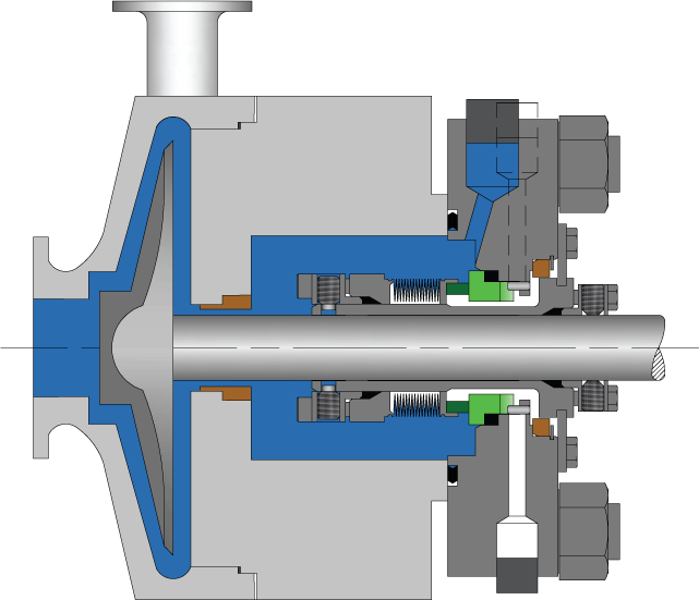
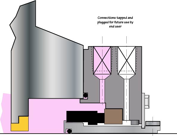
In Plan 61, only connections are supplied. Plan 61is sometimes used if the end user has a special or as yet undefined future use for the connections. Flush, Quench and Drain connections are supplied and plugged with plastic plugs.

Needing your expertise on seal plush plan 11 + 61 to be used on 98wt% Sulfuric Acid Unloading Pump. Original plan is 11 + 62 which is better. However because water or steam is not allowed (not recommendable) as a quenching media because water or condensate will react with the process fluid (sulfuric acid)original plan was changed. Is this reliable?
11+61 (recommendation of the pump vendor because water or steam is not allowed (not recommendable) as a quenching media because water or condensate will react with the process fluid (sulfuric acid).
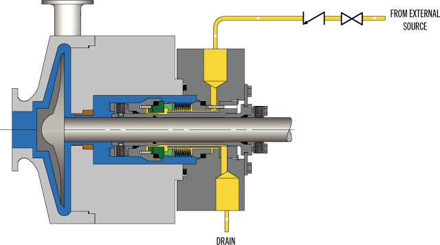
API Plan 62 delivers an external quench fluid to the atmospheric side of the seal. A typical application in a refinery is the prevention of coking on seal faces in hot hydrocarbon service by employing a steam quench. Nitrogen or clean water may also be used to quench or cool and clean the atmospheric side of the seal.
See page 77 of the Mechanical Seal Support Systems Application Guide for additional details and ordering information. Contact your authorized Swagelok sales and service center for information on optional components.
Single cartridge seal with double hydraulic balancing. The seal has a V-ring to contain the continous quench, ideal for pumps with fluids that tend to crystallise on the atmosphere and which require washing.

API Standard 682, titled "Pumps - Shaft Sealing Systems for Centrifugal and Rotary Pumps," is the American Petroleum Institute (API) standard for end-face mechanical seals.centrifugal pumps. It is based on the combined knowledge and experience of seal manufacturers, engineering companies, and end users. API 682 is primarily intended for use in the petroleum, natural gas and chemical industries, but is often referenced for other types of equipment and industries.
By the late 1980s, mechanical seals had been accepted as the preferred method for sealing rotating pumps for many years. However, mechanical seal standards were generally buried in other standards such as DIN 24960, ANSI B73, and API 610. All of these standards were primarily pump standards and any references to seals were directed at how mechanical seals would interact with pumps.
API 610 is the API standard about centrifugal pumps and is primarily intended for use in the petroleum, natural gas and chemical industries. Although the 1st through 7th Editions of API 610 included specifications for mechanical seals, beginning with the 8th Edition, API 610 defers to API 682 for seal specifications.
In the late 1980s a group of refinery equipment engineers and managers began to compare sealing solutions in refinery applications. This group, led by V. R. Dodd of Chevron, came up with a general plan and the American Petroleum Institute (API) agreed to establish a standard for mechanical seals: API 682. A Task Force was formed in 1990 and the first meeting was held in January 1991. This Task Force was composed of fourteen members from various refineries, seal and pump manufacturers. API 682, First Edition, was published in October 1994.
One interesting aspect of API 682 is that it includes a strong set of defaults. That is, unless the user indicates otherwise, API 682 makes default choices for specifics such as:
Some statements within API 682 are normative, that is, required, whereas others are informative, that is, descriptive but not required. In particular, many of the illustrations are informative. This distinction has not always been apparent to the reader.
The first edition of API 682 was entirely new although parts of it were extracted from the pump standard API 610 and existing API standard paragraphs.
Although this mission statement no longer appears in the standard, it remains the basic principle driving the work of the API 682 Task Force and its relevance remains the same for the 4th Edition as it did for the 1st.
In addition to providing requirements for mechanical seals, the 1st Edition of API 682 also provided a guide on how to select the correct seal for a number of common refinery applications. In order to provide this seal selection guide, it was necessary to categorize applications into a number of services:
Prior to API 682, 1st Edition, multiple seals were designated as being either “tandem” or “double” seals; however, advances in seal design had rendered these classic terms obsolete. As a result, there was some confusion on how multiple seals were designated. The task force decided to use a more descriptive designation and chose to define dual seal arrangements. A dual seal would be two sets of sealing faces used in the same seal chamber. The fluid between these two sets of sealing faces could be either pressurized or unpressurized. Three standard arrangements were defined:
After having defined the services, seal types, and seal arrangements, a series of flowcharts were created to help in selecting a seal type, special materials or design requirements, and supporting piping plans.
API 682 seals were to have a high probability of three years of reliable service. In order to prove this, seal performance testing on process fluids under representative pressures and temperatures was required. These performance tests are called “Qualification Tests”.
The general idea of the qualification test was to prove that the design was sound. The goal of the qualification test was to simulate a long-term steady state run followed by a process upset. The simulated process upset consisted of pressure changes, temperature changes and included loss of flush. The results of these tests were made available to the purchaser for evaluation. There was no acceptance criteria presented in API 682 1st Edition.
In addition to the qualification test of the design, every API 682 seal, whether new or repaired, is to be pressure tested with air before being shipped to the end user.
One of the major criticisms of API 682 1st Edition was that all the seals were “heavy duty” and therefore expensive with no alternatives for easy services. To some degree, this was intentional and was done in order to reduce inventory, promote familiarity with a limited number of seal types and to increase reliability. Another criticism of API 682 1st Edition was that it considered only API 610 pumps and only refinery applications. The chemical and petrochemical industries routinely use ASME pumps in addition to API 610 pumps. Broadening the scope of pumps covered by API 682 would allow standardized seals to be applied in a greater number of industries.
In 2nd Edition, the organization of API 682 was changed to conform to ISO standards: This reorganization means that there is no simple cross reference guide between 1st edition and 2nd edition paragraph numbers.
The 2nd Edition introduced the concept of seal categories. A seal category describes the type of pump into which the seal will be installed, the operating window, the design features, and the testing and documentation requirements. There are three categories designated as Category 1, 2, or 3.
Category 1 seals are intended for non-API-610 pumps. This category is applicable for temperatures between –40°F and 500°F (-40°C and 260°C) and pressures to 315 PSI (22 bar).
Category 2 seal are intended for API-610 This category is applicable for temperatures between –40°F and 750°F (-40°C and 400°C) and pressures to 615 PSI (42 bar).
Category 3 seals are essentially the original seals of 1st Edition and are also intended for API-610 pumps. Category 3 seals are intended for the most demanding applications. This category is applicable for temperatures between –40°F and 750°F (-40°C and 400°C) and pressures to 615 PSI (42 bar). Design features include a distributed flush and floating throttle bushing for single seals. Additional documentation must be also provided.
Containment seals are the outer seal of Arrangement 2. In the 2nd Edition, containment seals can be used with a liquid buffer fluid, a gas buffer fluid or without a buffer fluid. In the case of a dry running containment seal, the containment seal will be exposed primarily to buffer gas or vaporized process fluid. Such containment seals must therefore be designed for continuous dry running while meeting the reliability goals of the standard. Dry running containment seals may be either contacting or non-contacting.
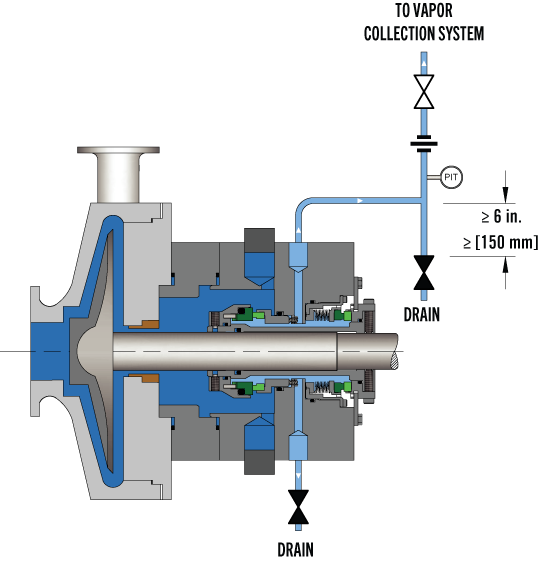
Non-contacting inner seals are also introduced for Arrangement 2. One of the primary targets for non-contacting inner seals is in flashing hydrocarbon services. In some of these services, it is impossible to obtain adequate vapor margins to prevent flashing of the fluid in the seal chamber. This seal will be used with a dry running containment seal and the leakage past the inner seal will be piped to a vapor recovery system.
The other new seal type introduced in 2nd Edition was the dry running gas seal used in Arrangement 3. This seal is designed to run on a gas barrier fluid such as nitrogen.
Several new piping plans were introduced in the 2nd Edition. These included additional options for dual pressurized liquid seals as well as new piping plans to support containment seals and dual pressurized gas seals.
One of the strengths of the 1st Edition was to provide qualification tests in which seal vendors would be required to prove the suitability of their seals for a given service. The 2nd Edition expanded on these requirements by adding new tests for containment seals and dual gas seals as well as defining acceptance criteria for all tests.
For all practical purposes, API 682 3rd Edition is the same as 2nd Edition. The completed 2nd Edition was submitted to the ISO Organization for approval as their ISO 21049. At the time, API and ISO had an agreement to jointly issue standards. The ISO Organization made slight editorial changes to 2nd Edition, including correcting typographical errors and unit conversions. Therefore, API had to re-issue a corrected 2nd edition but choose to label it as 3rd edition. API 682 3rd Edition was published in September 2004.
API and ISO no longer have the agreement to jointly issue standards. The 2004 issue of ISO 21049 is the only issue and plans to update it are unknown.
Seal Configuration refers to the orientation of the seal components in an assembly. In previous editions, orientations were defined as face-to-back, back-to-back, and face-to-face and these terms are carried over into the 4th Edition. In 4th Edition, any orientation (face to back, back to back, face to face) can be used in a dual seal provided that the design features are appropriate to the functionality of that particular arrangement.
Fourth Edition added additional specifications for clearances, placed these requirements in the form of tables and noted that seal components are not to be considered as “shaft catchers” to restrict shaft movement. The minimum clearances specified apply only to equipment within the scope of the standard. Equipment outside that scope, such as non-cartridge seals, older pumps, non-API 610 pumps and certain severe services, might benefit from larger clearances.
Before API 682, API 610 (the pump standard) used a simple seal code to specify seals. API 682 attempted to use a more comprehensive seal code; however, that code changed with every edition of API 682. The 4th Edition code, described in Annex D, is probably the best to date and includes some concepts and codes from the historical API 610 seal code.
Annex G provides illustrations and a short tutorial about each piping plan. As has been the case for every edition, changes were made to the standard piping plans. In particular, the piping plans now default to using transmitters with local indicators as part of the instrumentation.
API standards are reviewed every five years and re-issued every ten years. A new Taskforce for API 682 was formed in 2017 and preparations for 5th Edition are underway.
Buck, G. S., Huebner, M. B, Thorp, J. M., and Fernandez, C. L. “Advances in Mechanical Sealing – An Introduction to API-682 Second Edition”, Texas A&M Turbomachinery Symposium, 2003.
API Standard 682, Second Edition, 2001, “Pumps – Shaft Sealing Systems for Centrifugal and Rotary Pumps,” American Petroleum Institute, Washington, D.C.
API Standard 682, Third Edition, 2004, “Pumps – Shaft Sealing Systems for Centrifugal and Rotary Pumps,” American Petroleum Institute, Washington, D.C.
API Standard 682, Fourth Edition, 2014, “Pumps – Shaft Sealing Systems for Centrifugal and Rotary Pumps,” American Petroleum Institute, Washington, D.C.

Sealing technology by EagleBurgmann is used worldwide in oil and gas industries, refineries, the petrochemical, chemical, and pharmaceutical industries, food processing, energy, water, mining, paper, aerospace, and other industries. Close to 5,800 employees provide their ideas, solutions, and commitment so that customers can rely on our sealing technology.
In the past there was only one Plan 53, but with the 2nd Edition of API 682 and the 1st Edition of ISO 21049 other variations of Plan 53"s were created.
Plan 53A is the former Plan 53. Plan 53B is what had been in the past denoted as Plan 53 Modified; this is especially popular in European and other countries in the Middle East. Plan 53C is a variation of this that has also been used in the past and is now formally recognized.
The major difference in the plans is that Plan 53A uses an external reservoir, while Plans 53B and 53C run within a closed loop system with a make-up system piped to it for replenishment of the barrier fluid.
In dual pressurized sealing arrangements the inner process seal can have its own flush plan; in such applications the complete flush plan system designation should include both plans. For example, Plan 11/53A means that the inner seal has its own flush plan, Plan 11. The API/ISO default is for no separate flush plan when using any of the Plan 53"s, but this can vary with the application conditions.
With the older traditional back-to-back seal arrangement the inboard seal usually does not require a separate flush. In applications such a hydrofluoric acid, where it is both extremely hazardous and corrosive, a Plan 32 can be used in conjunction with a Plan 53. The dual pressurized face-to-back seal arrangement eliminates some of the potential problems associated with the back-to-back design. This face-to-back seal arrangement sometimes incorporates a reverse pressure capability that is not a default with the back-to-back design.
Also, face-to-back arrangements do not have a dead zone underneath the inboard seal that can become clogged by dirty process fluid and lead to seal hang-up. However, the face-to-back arrangement is not a cure-all. With the product on the seal O.D. and with it being used on API pumps that still incorporate throat bushings, it is advantageous to provide a flush for the inboard seal on a number of applications.
Abrasives can accumulate in the more closed API type seal chambers compared to the newer generation chemical duty pumps with large cylindrical bore or tapered bore chambers. The use of a Plan 11 or similar bypass type flush for the inner seal has advantages. It can help keep the seal chamber clean. It also has an improved overall heat transfer setup versus just using a Plan 53 system alone.
In comparison to a Plan 54, Plans 53A/B/C are usually less complex and less expensive. With Plans 53A/B/C, both the inner and the outer seals are lubricated by the barrier fluid, which can be selected for optimum seal performance. Plans 53A/B/C are usually selected for dirty, abrasive, or polymerizing process services which might be difficult to seal directly with single seals or with dual unpressurized seals using a Plan 52. There will always be some leakage of the barrier fluid into the process with any pressurized system.
With some of the Plan 53 systems the volume of barrier fluid is limited, especially compared to a Plan 54 system. Venting of the seal chamber is essential for all Plan 53"s where vapor locking can if vapor bubbles collect near the pumping ring or in the piping.
Plan 53A uses an external reservoir to provide barrier fluid for a pressurized dual seal arrangement. Reservoir pressure is produced by a gas, usually nitrogen, at a pressure greater than the maximum process pressure being sealed. The gas pressure is regulated by a system that is outside the schematic of the piping plan. Circulation of the barrier fluid is maintained by an internal pumping ring.
Like Plan 52 reservoirs, cooling is accomplished internal coil of tubing to remove the heat. Also like Plan 52 reservoirs, the volume of barrier liquid can vary from two gallons to 5+ gallons, where API and ISO standards specify 3-gal and 5-gal, depending upon the shaft diameter.
For non-API specifications, smaller reservoirs - typically 2-gal - are often used, especially at ambient pumping temperatures. Pressure alarms, pressure gages and level switches are typically standard equipment and are required by API 682/ISO 21049.
The usual guideline for Plan 53 barrier pressures is that they be a minimum of 20-psi to 50-psi above the maximum process pressure seen by the seal. Barrier pressure is normally supplied by a plant wide distribution system. Nitrogen bottles should not be used as they require a lot of attention and maintenance.
API 682/ISO 21049 recommends that the system be limited to 150-psig due to gas entrainment into the barrier fluid. Field experience has shown that with the proper barrier fluid, Plan 53A systems can be used up to 300-psig if the temperature is controlled to less than 250-deg F. A variation to this would be to use an accumulator to eliminate gas entrainment.
Disadvantages (vs. other Plan 53 systems)The barrier fluid in Plan 53A is subject to gas entrainment due to direct exposure to the pressurizing gas. Different barrier fluids have varying levels of gas entrainment.
Installation should be limited to a single seal installation even on between bearing pumps. Therefore for a large number of installations, Plan 53A can be more expensive than Plan 53B or 53C.
nlike a Plan 53A that incorporates a pressurized reservoir within the circulation loop, Plan 53B incorporates a bladder type accumulator along with the piping and an air or water cooled heat exchanger to provide for barrier fluid capacity.
Some installations use finned tubing as the heat exchanger, but these should be used with caution as the heat removal depends upon a positive air flow across the tubing to be effective. Gas entrainment is not a problem with this plan since it incorporates bladder accumulator to maintain the barrier pressure within the closed loop circuit.
The accumulator should be pre-pressurized to between 80 percent and 90 percent of the barrier pressure. This creates a problem in that it limits the volume of fluid within the Plan 53B circuit. The majority of the accumulator volume is gas. The basic setup is comprised of two parts; the closed loop circulating system made up of the piping and heat exchanger and the make up system.
Flow in the circulating system is usually induced by an internal pumping device. The make up system can be configured a number of ways based upon the customer"s preference, ranging from a simple hand pump to an elaborate pumping system feeding multiple pumps/seals.
Like Plan 53A, the flow rate of the Plan 53B circuit is controlled by the pumping ring design, peripheral speed, barrier fluid viscosity, and resistance of the piping circuit; the piping circuit of 53B includes a heat exchanger. The sizing of the heat exchanger depends upon the heat load of the system. The heat exchanger should be designed to contribute minimum resistance.
API 682, 3rd edition does not provide guidelines for sizing the accumulator of Plan 53B, but the total fluid volume of the system should be about the same as the volume of a 53A system.
Disadvantages (vs. other Plan 53 systems)The volume of fluid within the closed loop circuit is very limited, as little as one-half gallon in some instances.
With the limited fluid volume the barrier fluid gets thermally cycled on a much more frequent basis than a Plan 53A, so the service life of the fluid is reduced.
The finite volume of the accumulator requires a designed pressure operating range between refills (in excess of that required for a Plan 53A) and this must be built into the pressure rating of the seals.
The separate heat exchanger introduces additional flow resistance to the piping system and will have a lower flow rate than an otherwise identical Plan 53A.
Plan 53C is a variation of Plan 53B that uses a piston accumulator to track the pressure of the seal chamber. In Plan 53C, the piston accumulator has a reference line from the seal chamber to the bottom of the accumulator. There are differences in diameter of the internal piston so that a higher pressure is generated on the top half, which in turn is piped to the circuit loop into and out of the seal chamber.
Similar to Plan 53B, there is no gas pressurizing the barrier fluid so there is no chance of gas entrainment. Also, like Plan 53B flow is generated by a pumping ring through a heat exchanger. The heat exchanger can be water cooled, air cooled or can be finned tubing if the heat load is small enough. This system should be used with caution, as the reference line to the accumulator is subject to the process fluid. The process fluid may be corrosive, abrasive, or a slurry that could potentially clog the pressure reference line threatening the tracking ability of the system.
The advantages and disadvantages are the same as the Plan 53B system. Additionally, the disadvantage of this system is that pressure spikes or pressure drops in the process pressure will vary the pressure on the outer seal that may create a temporary leakage condition. Also, tracking pressures can always be subject to delays that can cause a temporary loss of positive pressure differential across the inboard seal.
PHOTO : https://www.eagleburgmann.com/media/literature-competences-products-solutions/division-mechanical-seals/competences/brochure-barrier-buffer-media-for-mechanical-seals
The API plans presented in this section are developed in accordance with the API 682, 3 revision / API 610, 10 revision standard. This is the standard scheme of the drilling pipes, which are widely used in industry. It is possible to customize these plans to meet the needs of customers.
The flushing of the seal from the outlet to the seal chamber via the aperture and flushing the seals from the seal chamber to the inlet through the diaphragm
Diagram of the system for ensuring the operation of a single seal with an impeller that creates fluid circulation through the stuffing box along an Autonomous circuit.
If the pressure in the oil seal chamber of the pump is less than the design pressure of the tank (4mpa), the installation of a safety valve on the tank pipelines is not required.
"Tandem" type mechanical seals can be used both with a refrigerator at the pump"s working medium temperature up to 400 °C, and without it at the working medium temperature up to 150 °C.
Diagram of the system for ensuring the operability of a double seal with a tank. The system operates at constant maintenance of the pressure of the shut-off fluid (pressure in the tank) within:
At pump working medium temperatures up to 150°C seals are used without a refrigerator, at the temperature of the pumped medium 150...400°C-with a refrigerator.
For servicing seals of a group of pumps that perform the same task and are located close to each other, it is possible to use the system diagram shown below.
The most commonly used scheme is a system with the supply of shut-off fluid from a separate pipeline with an overpressure m through the seal of the threads.
At pump working medium temperatures up to 150°C seals are used without a refrigerator, at the temperature of the pumped medium 150...400°C-with a refrigerator.
For condensate pumps, where dry operation of the mechanical seals is not excluded, the guaranteed supply of the shut-off fluid can be carried out according to the following scheme.
At pump working medium temperatures up to 150°C seals are used without a refrigerator, at the temperature of the pumped medium 150...400°C-with a refrigerator.
API plan 65 allows you to determine the volume of leaks through the mechanical seal. If the friction pair breaks through, the external strapping tank is equipped with an upper-level alarm that will trigger as soon as the liquid level in the tank increases.


 8613371530291