
api plan 62 mechanical seal quotation

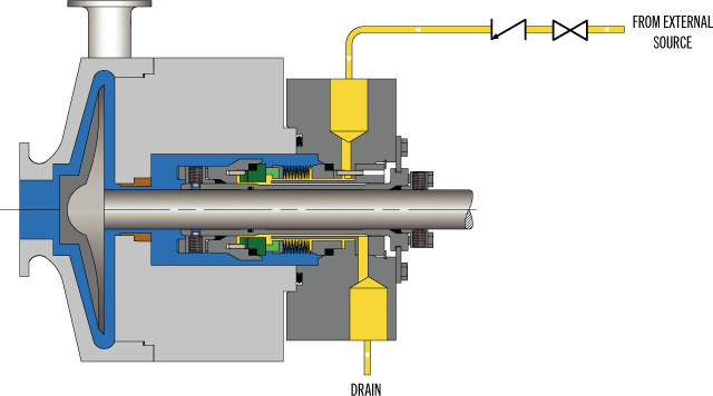
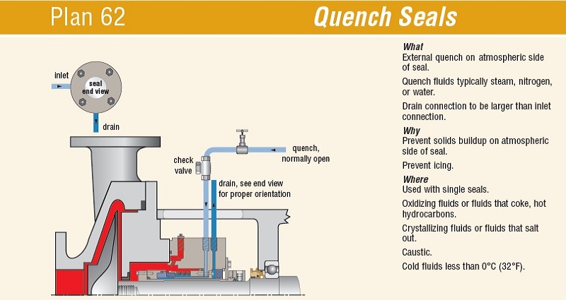
API Plan 62 delivers an external quench fluid to the atmospheric side of the seal. A typical application in a refinery is the prevention of coking on seal faces in hot hydrocarbon service by employing a steam quench. Nitrogen or clean water may also be used to quench or cool and clean the atmospheric side of the seal.
See page 77 of the Mechanical Seal Support Systems Application Guide for additional details and ordering information. Contact your authorized Swagelok sales and service center for information on optional components.
Seal Support Systems operate to control the fluid in between and around the seal faces whether cleaning, cooling or heating the seal media or providing a separate fluid to the mechanical seal.
Some applications are simply not suitable for mechanical seals e. g applications which are corrosive, abrasive, crystallizing or precipitative. In order for a mechanical seal to operate under these applications with reasonable mean time between failure (MTBF), either the seal fluid requires treatment before coming into contact with the seal faces or an external fluid is required which is compatible with the process. Also double mechanical seals will require some sort of fluid to act as a buffer or barrier fluid andthe system which provides this buffer or barrier fluid are Seal Support Systems.
A seal plan is used in conjunction with the API 682 Standard and it is a way to formalise the different seal support systems into a standard. It consists of seal flush plans, buffer & barrier fluid plans, quench plans and gas supply plans.
The API Plan 53A is a dual seal plan where a barrier fluid is supplied to a double mechanical seal between the 2 sets of faces of the mechanical seal.
Plan 62 is a quench seal plan where a fluid is supplied to the space between the atmospheric side of the mechanical seal and the throttle bushing on the shaft.
Flowserve provides Seal Support Systems for in accordance with API 682 but can also provide systems outside of this standard, if the application dictates.
Our Mechanical Seal specialists can advise you on the appropriate selection of a seal support system which will deliver years of reliable service and operating cost savings in the longer term.
After more than five years of planning, the American Petroleum Institute (API) is preparing to release the 4th edition of API Standard 682 (ISO 21049:2011). The API 682 standard, which dates back to 1994 and is formally known as Shaft Sealing Systems for Centrifugal and Rotary Pumps, offers specifications and best practices for mechanical seals and systems to pump end users.
The standard’s latest edition began to take shape in 2006, when API formed a 4th edition task force to respond to end users’ questions and comments about previous editions. The task force soon realized that major changes, including reorganization and editing, would be necessary. While addressing every aspect of the resulting 4th edition (which is more than 250 pages long) would be impossible, this article summarizes the standard’s main points.
Those who use API 682 should understand the standard’s scope and remember that the standard does not include specifications for equipment outside that scope, such as engineered seals or mixers. Another important but often misunderstood point is that API 682’s figures are illustrative and not normative in their entirety.
For example, one of API 682’s figures shows a fixed throttle bushing combined with a rotating Type A seal, but seal manufacturers do not always have to combine these two components. The standard provides normative details in clauses and tables to help purchasers distinguish between requirements and suggestions.
The 4th edition continues to divide seals into three categories, three types and three arrangements. For all practical purposes, seal manufacturers can combine a seal’s component parts into nearly any orientation or configuration. Each orientation and configuration has advantages and disadvantages with respect to certain applications, performance and system disturbances.
Before the 4th edition, API 682 did not specify a minimum clearance between the inside diameter of a stationary seal part and the outside diameter of a rotating seal part. The 4th edition specifies this minimum clearance—typically the clearance between the sleeve and the mating ring. The specified clearances are representative of standard clearances that end users have used for decades. End users should not consider seal components to be “shaft catchers” to restrict shaft movement. The minimum clearance specified in API 682 also applies only to equipment within the standard’s scope. Equipment outside that scope, such as non-cartridge seals, older pumps, non-API 610 pumps and certain severe services, might benefit from larger clearances.
The new standard also updates the default bushings for the gland plate for the three seal categories. Fixed throttle bushings are now the default for Category 1 only, while floating bushings are the default for Categories 2 and 3.
While the 4th edition features the recommended seal selection procedure from the standard’s first three editions, it adds an alternative selection method in Annex A. Proposed by task force member Michael Goodrich, this alternative method recommends using material data sheet information to select a sealing arrangement.
Plan 65 is now subdivided into 65A and 65B. End users can use Plan 65A to detect an excessive leakage flow rate and Plan 65B to detect a certain amount of cumulative leakage.
Plans 66A and 66B are new to the standard, although end users have used them previously in pipeline applications. These plans detect and restrict excessive leakage rates in case of an Arrangement 1 seal failure.
The 4th edition now requires Plan 52, 53A, 53B and 53C systems to have a sufficient working volume of buffer or barrier fluid for at least 28 days of operation without refilling. As a point of reference, the default reservoir for Plans 52 and 53A has a three-gallon capacity, or pot, for pump shafts smaller than 2.5 inches and a five-gallon pot for larger shaft sizes. Plan 53C must have the same working volume of fluid as Plan 53A. For Plan 53B, the default bladder and accumulator sizes are five gallons and nine gallons, respectively. The design of Plan 53B systems can be complex, especially when ambient temperatures vary widely, and purchasers should become familiar with the calculations and procedures in the 4th edition’s Annex F tutorial. The new edition also discusses the option of adding a pressure gauge and isolation valve to check the accumulator or bladder’s integrity in a Plan 53B system.
The 4th edition has revised the data sheets in Annex C extensively to make them the same for all seal categories. Only two data sheets are included in the 4th edition—one in metric units and one in U.S. customary units. The new edition also folds Annex J into Annex E.
Previous editions of API 682 required metal plugs and anaerobic sealants when shipping new or repaired cartridges. After much debate, the task force decided that threaded connection points should be protected with plastic plugs for shipment. These plastic plugs should be red and have center tabs that operators can pull easily to distinguish the plugs from metal plugs. Shippers should also attach yellow warning tags to the plugs to indicate that end users need to remove the plugs before operation.
Although tutorial notes are scattered throughout API 682, this edition expands the tutorial section, Annex F, from seven pages to 42 pages. The expanded annex includes illustrative calculations. In particular, users interested in systems such as Plan 53B will find Annex F to be useful.
The 4th edition of API 682 is the product of more than 20 years of discussion, debate, usage and peer review. It includes a strong set of defaults and is by far the best and most logical starting point for mechanical seal and systems use. Equipment operators should take the time to familiarize themselves with API 682 to get the most out of this comprehensive standard.
Most pump experts would agree that mechanical seals on a rotating industrial pump are one of the most important components regarding pump performance and longevity. Rotating industrial pumps are designed with double mechanical seals located at the shaft that connects the impeller or rotor to the motor. As the motor applies force to the shaft, the shaft spins, which in turn, spins the impeller or rotor which is connected to the far end of the shaft. This spinning action of the shaft and impeller or rotor is what produces the flow rate of the pump. The double mechanical seals are a wear component that must be replaced periodically or the pump will not perform as expected, or even worse if these seals fail it can cause a catastrophic failure resulting in substantial cost to repair or replace the pump.
Most often, failure of the mechanical seals is due to being exposed to excessive heat that is generated by the turning or spinning action of the shaft. This build-up of excessive heat at this area of the pump is also the reason why many rotating industrial pumps cannot operate in a run-dry condition. When a pump runs dry without fluid circulating through the wetted path, a greater amount of heat is generated at the mechanical seals. Subjecting the mechanical seals to a greater amount of heat than what they can withstand causes premature failure of the seals.
A solution to avoiding the overheating of mechanical seals in a rotating industrial pump is Seal Support Systems. Seal Support Systems are designed to flush the mechanical seal area of the pump with fluid. This flushing action reduces the build-up of heat, increases the longevity of the pump, and avoids premature failure of the mechanical seals due to overheating.
There are a number of different Seal Support System designs available on rotating industrial pumps. Some of the different designs available meet the American Petroleum Institute (API) standards for pumps that are to be used in the Oil and Gas industry. A couple of the most prevalent API standards for Seal Support Systems API Plan 53A and API Plan 62. Both of these systems are designed differently; The API Plan 53A Seal Support System is designed with a closed-loop system, and API Plan 62 Seal Support System is designed with an open system where the flushing fluid is immediately discarded from the pump directly after the flushing fluid flows through the mechanical seal area and expels the heat.
Both of these seal support systems are very effective at reducing heat build-up that can destroy mechanical seals. Although both of the types of seal support systems reduce heat build-up, some environments require the use of a closed-loop seal support system to avoid the flushing fluid from exiting the pump and contaminating the area that the pump is operating.

FLUSH PLANS FOR MECHANICAL SEALS – INTRODUCTIONPumps and seals are being installed into increasingly difficult services. Forsuccessful operation of mechanical seals, the environment and care of the sealsrequire more sophisticated seal chambers and flushing arrangements. This sectionof the Dean Pump Price Book is designed to allow the application and pricing offlush plans suitable to meet the requirements for the mechanical seal.The American Petroleum Institute (API) has defined certain seal flusharrangements known by their plan numbers. Later, the flush plans developed forthe ANSI standard followed suit and placed the digits "73" in front of the API plannumber to achieve some standardization within the process industry. Thus, APIplan 11 becomes and ANSI Plan 7311.Dean Pump has worked with many engineering houses and customers over theyears and has developed a great deal of experience with sealing systems. WhileDean will quote any flush system requirement as requested by a particularcustomer, it has been found that the API/ANSI systems generally meet or exceedmost customer requirements. In addition, Dean Pump developed the Seal GuardEnvironment systems that provide the ultimate mechanical seal flush plan. Forsystems that do not require ANSI/API flush plans, Dean Pump has also includedthe P1200 loop, which is a basic low cost flush plan to satisfy the economyminded customer.The experience of Dean Pump is contained in these price pages. Many of theflush plans are divided into "Toxic/Flammable" and "Non-Toxic/Non-Flammable“services. The information on these plans along with the details described in the"Special Notes" section can be used as a guide in quoting and discussing optionswith customers. The "fine print" in the Special Notes section provides a multitude ofdetails about each flush system. For example, a customer requesting all socketwelded connections can not have every connection welded. Some accommodationmust be made for disconnecting the system. Being aware of the requirements ofthe customer and the manufacturing limitations of the product is extremely helpful.API flush plans are based on the 7 th Edition of API610. Newer versions of the APIspecifications has limited the cooling and flushing options available.Finally, if there are any doubts, questions, or comments, please feel free to call theFactory and the seal vendor.Effective: FEBRUARY 2011 • Replaces: NEWPage 1
SEAL GUARD SYSTEMS – PRODUCT DESCRIPTIONSeal Guard systems are designed to provide a clean liquid for seal flushing thatprovides protection for the mechanical seal in the pump seal chamber. Dean Pumpoffers two basic systems to guard against mechanical seal failure. These systemswill also help to prolong the life of the seal. Both systems are filtration systemsinstalled into the seal flush lines to remove stray abrasive particles which causeseal face wear.Seal Guard A - is designed for filtration only. Particles larger than 10 microns arefiltered from the system using clean-able or replaceable 316SS woven filterelements.Seal Guard B - is designed for high temperature applications and includes a heatexchanger installed ahead of the replaceable filter elements for both filtration andtemperature control.Seal Guard systems are most often used with MIN-FLO Bushings in the pump sealchamber. These bushings restrict the flow from the seal chamber back into thepump during operation and increases the effectiveness of the Seal Guard system.Seal Guards can be used on any pump product line. Their sale is not limited toDean Pump products. Seal Guards are hydrostatically tested but do not meet anyindustrial standard and are not for application to API610 series pumps. Seal Guardapplications must be limited to iron or steel pumps and are not suitable forapplications that require alloy materials.The Seal Guard system is fully described in Bulletin A2000.Effective: FEBRUARY 2011 • Replaces: NEWPage 2
SEAL GUARD SYSTEMS – (See Note #1)Model A Series – Filtration Only (See Note #2)Mounted on Pump BaseplateModel Description List PriceA500T A Series Seal Guard - Filtration - Threaded Connections $4,483A500F A Series Seal Guard - Filtration - Flanged Connections C/FA700T A Series Seal Guard - Filtration - Threaded Connections C/FBD500TB500TModel B Series – Filtration and Cooling (See Notes #2 & #3)Mounted on Separate BaseplateModel Description List PriceBD200T B Series Seal Guard - Cooling & Filtration - $5,248Threaded Connections & Duplex FilterB400T B Series Seal Guard - Cooling & Filtration - $5,248Threaded Connections & Simplex FilterB400F B Series Seal Guard - Cooling & Filtration - C/FFlanged Connections & Simplex FilterB500T B Series Seal Guard - Cooling & Filtration - $6,226Threaded Connections & Simplex FilterBD500T B Series Seal Guard - Cooling & Filtration - $8,240Threaded Connections & Duplex FilterNotes:1. Seal Guard systems are not rated for API application and are suitable for pumps in steel or iron construction only. Do notuse for 316SS or other alloy applications.2. The product description letters and numbers are as follows:First Letter - Seal Guard Series A - Filtration Only; B - Cooling and Filtration. (The letter D following in the second positionindicates a Duplex arrangement.); 3 Digit Number indicates the pressure rating of the Seal Guard system in psi.;Final Letter: T - Threaded Construction; F - Flanged Construction3. The heat exchangers provided for Seal Guard B are furnished with a steel shell and 316SS tube as standard.Effective: FEBRUARY 2011 • Replaces: NEWPage 3
DEAN P1200 ECONOMY FLUSH PLAN FOR PROCESS PUMPSPlan Description:Dean Plan P1200 systems include piping (or tubing) from the pumpdischarge gauge connection to the seal flush connection on the pumpbackhead or seal gland. These plans include all piping and/or tubing.List Prices (Notes 1 & 3)Carbon SteelCarbon SteelFitted 316SS Pipe 316SS PipeSystem Description (Note #2) Tubing Threaded ThreadedRecirculation of Pumpage from Pump Case toP1200 Seal Without Orifice (Similar to API Plan 11 orANSI Plan 7311) VALVE NOT INCLUDED$216 $329 $456 $692Valve Valve for Recirculation Line $205 $762 $205 $762General Notes:1. For all other flush plans, refer to API/ANSI Flush Plans shown elsewhere for your particular requirements.2. The plan with carbon steel tubing uses carbon steel fittings with 316SS tubing.3. Connections on the casing require a price adder for discharge gauge connections and may require an additional price adderif the seal chamber requires back drilling.Effective: FEBRUARY 2011 • Replaces: NEWPage 4
SOME COMMENTS AND RECOMMENDATIONSABOUT API/ANSI FLUSH PLANSThere are two organizations in the United States which have taken the lead in developingacceptable standards for the pump industry. The American Petroleum Institute (API) and AmericanNational Standards Institute (ANSI) have outlined a number of flush plans which encompass themajority of applications. API610 is mainly recognized as a standard which defines the qualityrequirements of a pump and/or system. ANSI-B73.1 is viewed as more of a dimensional and featurestandard. ANSI plans are designated the same as API plans except for the addition of a "73" prefixon the plan number. For example, an API Plan 21 is designated as an ANSI Plan 7321.API and ANSI flush plans are similar and upon initial examination look nearly identical. However,there are definite differences in their construction. Often, API flush plans, which are historicallylocated in refinery environments, are piped and welded. ANSI plans, on the other hand, can utilizetubing. Another notable difference is in the API plan 52/53 and the ANSI plan 7352/7353. APIspecifies Schedule 40 minimum thickness vessels. ANSI allows for the use Schedule 10 vessels. Allof the plans are offered in steel and stainless steel construction. They also have differingconstructions for Toxic/Flammable or Nontoxic/Nonflammable applications.Meeting the customer"s specific requirements is the most important consideration in applying theseplans. Many customers modify their individual requirements from the API and ANSI specifications.Sometimes these are more stringent rules than the API and ANSI specifications. These must takeprecedence over the standard flush plans. There are some limitations as to what the flush plans canor cannot accomplish. The Special Application Notes section on each sheet identifies the particularlimitations of each of the flush plans. For example, a flush loop which requires socket welded jointscan not have all the connections welded some provision must be made to allow for disassembly andrepair.When applying a particular flush plan to a specific job, great care should be taken to insure theneeds of the customer are met. Do not select a plan based solely upon pricing. In general, most APIplans require piping and many require welded joints. Note that these are the most expensive plans.A few API services permit the less expensive plans but, the customer"s requirements takeprecedence. ANSI, on the other hand, is much less specific but still requires close analysis of thecustomer"s specifications and requirements for guidance. However, API plans are often seen onANSI type pumps. Oil companies are very likely to request the more expensive plan and will pay forit. Do not make errors in this area. If there is any doubt, or questions regarding plan selection, sendthe specification/ requirements to the factory for review. The factory will provide any comments,limitations, and pricing that is required.Effective: FEBRUARY 2011 • Replaces: NEWPage 5
API PLAN 11 - FLUSH PLAN FOR PROCESS PUMPS (Note #1)ANSI PLAN 7311 – FLUSH PLAN FOR CHEMICAL PUMPSPlan Description:API Plan 11 (ANSI Plan 7311) systems include piping (ortubing) from the pump discharge gauge connection throughan orifice to the seal flush connection on the pumpbackhead or seal gland. These plans include all piping,tubing, and the orifice. Refer to Note #B for additionalpump drilling.SYSTEMS FOR NON-TOXIC AND NON-FLAMMABLE APPLICATIONSSystem DescriptionDescription Special Notes Max. Press. Max. Temp. List PriceAASteel Threaded Pipe and Fittings with 316SS Tubingand Tube Connectors2, 3, 7, 19 500psi 800º F. $ 413AB Steel Threaded Pipe and Fittings 2, 5, 8 500psi 800º F. $ 627AC316SS Threaded Pipe and Fittings with 316SS Tubing andTube Connectors2, 3, 7, 19 500psi 850º F. $ 483AD All 316SS Threaded Pipe and Fittings 2, 5, 8, 500psi 850º F. $1,496SYSTEMS FOR TOXIC AND/OR FLAMMABLE APPLICATIONSSystem Description Special Notes Max. Press. Max. Temp. List PriceAESocket Welded Steel Pipe and Fittings with 316SS Tubingand Tube Connectors1, 4, 7, 19 500psi 300º F. $ 890AF Socket Welded Steel Pipe and Fittings 1, 6, 8 500psi 800º F. $1,124AGSocket Welded 316SS Pipe and Fittings with 316SS Tubingand Tube Connectors2, 3, 7, 19 500psi 300º F. $ 982AH All Socket Welded 316SS Pipe and Pipe Fittings 2, 5, 8 500psi 850º F. $1,577General Notes:A. ALL PUMPS - The plans are similar to but may not comply with API610, 5 th Ed. Review customer requirements as plansmay not comply with later editions or specific customer requirements.B. ALL PUMPS - Flush plans require one or more pump taps. Add the price of the discharge and suction gauge connections ifrequired. For clamped seat applications, consult factory.Special Application Notes:1. Pipe connections at the pump are threaded and are not backwelded.2. All pipe joints are threaded.3. Pipe nipples, threaded pipe fittings, stainless steel tubing, and compression type stainless steel tube connectors.4. Pipe, pipe nipples, socket weld pipe fittings, backwelded threaded pipe fittings, stainless steel tubing and compression typestainless steel tube connectors with threaded pipe connections that are not backwelded.5. Pipe nipples, threaded pipe fittings, and threaded pipe unions.6. Pipe, pipe nipples, socket weld pipe fittings, backwelded threaded pipe fittings, socket weld pipe unions.Effective: FEBRUARY 2011 • Replaces: NEWPage 7
API PLAN 12 - FLUSH PLAN FOR PROCESS PUMPS (General Note #A)ANSI PLAN 7312 – FLUSH PLAN FOR CHEMICAL PUMPSPlan Description:API Plan 12 (ANSI Plan 7312) systems include piping (ortubing) from the pump discharge gauge connection througha Y-strainer, and orifice to the seal flush connection on thepump backhead or seal gland. These plans include allpiping, tubing, and the orifice. Refer to Note #B foradditional pump drilling.SYSTEMS FOR NON-TOXIC AND NON-FLAMMABLE APPLICATIONSSystem DescriptionDescription Special Notes Max. Press. Max. Temp. List PriceBASteel Threaded Pipe and Fittings with 316SS Tubing andTube Connectors and Y-Strainer2, 3, 7, 9, 19 500psi 800º F. $ 638BB Steel Threaded Pipe and Fittings 2, 5, 8, 9 500psi 800º F. $1,123BC316SS Threaded Pipe and Fittings with 316SS Tubing andTube Connectors and Y-Strainer2, 3, 7, 9, 19 500psi 850º F. $ 939BD All 316SS Threaded Pipe and Fittings and Y-Strainer 2, 5, 8, 9 500psi 850º F. $1,736SYSTEMS FOR TOXIC AND/OR FLAMMABLE APPLICATIONSSystem Description Special Notes Max. Press. Max. Temp. List PriceBESocket Welded Steel Pipe and Fittings with 316SS Tubingand Tube Connectors and Y-Strainer1, 4, 7, 10, 19 500psi 300º F. $1,298BF Socket Welded Steel Pipe and Fittings and Y-Strainer 1, 6, 8, 10 500psi 800º F. $1,602BGSocket Welded 316SS Pipe and Fittings with 316SS Tubingand Tube Connectors and Y-Strainer2, 3, 7, 9, 19 500psi 300º F. $1,270BHAll Socket Welded 316SS Pipe and Pipe Fittings andY-Strainer2, 5, 8, 9 500psi 850º F. $1,817General Notes:A. ALL PUMPS - The plans are similar to but may not comply with API610, 5 th Ed. Review customer requirements as plansmay not comply with later editions or specific customer requirements.B. ALL PUMPS - Flush plans require one or more pump taps. Add the price of the discharge and suction gauge connections ifrequired. For clamped seat applications, consult factory.Special Application Notes:1. Pipe connections at the pump are threaded and are not backwelded.2. All pipe joints are threaded.3. Pipe nipples, threaded pipe fittings, stainless steel tubing, and compression type stainless steel tube connectors.4. Pipe, pipe nipples, socket weld pipe fittings, backwelded threaded pipe fittings, stainless steel tubing and compression type stainless steeltube connectors with threaded pipe connections that are not backwelded.5. Pipe nipples, threaded pipe fittings, and threaded pipe unions.6. Pipe, pipe nipples, socket weld pipe fittings, backwelded threaded pipe fittings, socket weld pipe unions.7. Stainless steel orifice plate in tube connector.8. Stainless steel orifice plate in pipe union.9. Y-strainer has stainless steel screen and 1/4" NPT (plugged) blow-off connection.10. Y-strainer has stainless steel screen and bolted cap without blow-off connection.19. This loop has stainless steel tubing and should not be used where chlorides are present.Effective: FEBRUARY 2011 • Replaces: NEWPage 8
API PLAN 21 - FLUSH PLAN FOR PROCESS PUMPS (General Note #A)ANSI PLAN 7321 – FLUSH PLAN FOR CHEMICAL PUMPSWHEN SPECIFIEDPlan Description:API Plan 21 (ANSI Plan 7321) systems include piping (ortubing) from the pump discharge gauge connection throughthe heat exchanger to the seal flush connection on thepump backhead or seal gland. These plans include allpiping, tubing, heat exchanger, and the orifice. The heatexchanger includes a steel shell and 316SS tubing. Ref.Note #B.SYSTEMS FOR NON-TOXIC AND NON-FLAMMABLE APPLICATIONSMAWP 500psi @System Description Special Notes 300º F 650º F 750º FCACBCCCDSteel Threaded Pipe and Fittings with 316SS Tubing andSteel Threaded Pipe and Fittings and Heat Exchanger316SS Threaded Pipe and Fittings with 316SS Tubing andAll 316SS Threaded Pipe and Fittings and Heat Exchanger2, 3, 7, 11, 13,2, 5, 8, 11, 13,2, 3, 7, 11, 13,2, 5, 8, 11, 13,Heat Exchanger (Steel Sheel & 316SS Tubing)(Steel Sheel & 316SS Tubing)Heat Exchanger (Steel Sheel & 316SS Tubing)(Steel Sheel & 316SS Tubing)19, 212119, 2121$3,301$3,663$5,016$5,229$3,301$3,663.$5,489$5,701$4,864$5,227$6,700$6,913ADD Temperature Indicator 13 C/F C/F C/FSYSTEMS FOR TOXIC AND/OR FLAMMABLE APPLICATIONSSystem Description Special Notes 300º FMAWP 500psi @650º F 750º FCESocket Welded Steel Pipe and Fittings and Heat Exchanger 1, 6, 8, 11, 12,(Steel Sheel & 316SS Tubing) 14, 21$4,286 $4,286 $5,849CFAll 316SS 316SS Pipe and Fittings and Heat Exchanger 2, 5, 8, 11, 13, C/F C/F C/F(Steel Sheel & 316SS Tubing) 21ADD Temperature Indicator with Thermowell 14 C/F C/F C/FGeneral Notes:A. ALL PUMPS - The plans are similar to but may not comply with API610, 5 th Ed. Review customer requirements as plans may not comply withlater editions or specific customer requirements.B. ALL PUMPS - Flush plans require one or more pump taps. Add the price of the discharge and suction gauge connections if required. Forclamped seat applications, consult factory.Special Application Notes:1. Pipe connections at the pump are threaded and are not backwelded.2. All pipe joints are threaded.3. Pipe nipples, threaded pipe fittings, stainless steel tubing, and compression type stainless steel tube connectors.4. Pipe, pipe nipples, socket weld pipe fittings, backwelded threaded pipe fittings, stainless steel tubing and compression type stainless steeltube connectors with threaded pipe connections that are not backwelded.5. Pipe nipples, threaded pipe fittings, and threaded pipe unions.6. Pipe, pipe nipples, socket weld pipe fittings, backwelded threaded pipe fittings, socket weld pipe unions.7. Stainless steel orifice plate in tube connector.8. Stainless steel orifice plate in pipe union.11. Heat exchanger has 1/4" diameter, 18 gauge, stainless steel tubes good for the maximum operating temperature and pressure of the pump.12. Heat exchanger connections are threaded and are not backwelded to allow replacement of the tube coil.13. Dial thermometer is 3" diameter, bi-metal, and screwed into pipe TEE and is furnished only when specified.14. Dial thermometer is 3" diameter, bi-metal, and screwed into a thermometer socket which is welded into pipe TEE and is furnished onlywhen specified.19. This loop has stainless steel tubing and should not be used where chlorides are present.Effective: FEBRUARY 2011 • Replaces: NEWPage 9
API PLAN 22 - FLUSH PLAN FOR PROCESS PUMPS (General Note #A)ANSI PLAN 7322 – FLUSH PLAN FOR CHEMICAL PUMPSWHEN SPECIFIEDPlan Description:API Plan 22 (ANSI Plan 7322) systems include piping (ortubing) from the pump discharge gauge connection througha Y-strainer, through the heat exchanger to the seal flushconnection on the pump backhead or seal gland. Theseplans include all piping, tubing, heat exchanger, and theorifice. The heat exchanger includes a steel shell and316SS tubing. Ref. Note #19.SYSTEMS FOR NON-TOXIC AND NON-FLAMMABLE APPLICATIONSMAWP 500psi @System Description Special Notes 300º F 650º F 750º FDADBDCDDSteel Threaded Pipe and Fittings with 316SS Tubing andSteel Threaded Pipe and Fittings and Heat Exchanger316SS Threaded Pipe and Fittings with 316SS Tubing andAll 316SS Threaded Pipe and Fittings and Heat Exchanger2, 3, 7, 9, 11, 13,2, 5, 8, 9, 11, 13,2, 3, 7, 9, 11, 13,2, 5, 8, 9, 11, 13,Heat Exchanger (Steel Sheel & 316SS Tubing) and Y-Strainer(Steel Sheel & 316SS Tubing) and Y-StrainerHeat Exchanger (Steel Sheel & 316SS Tubing) and Y-Strainer(Steel Sheel & 316SS Tubing) and Y-Strainer19, 212119, 2121$3,549$3,912$5,454$5,460$3,549$3,912$5,928$5,955$5,112$5,475$7,138$7,145ADD Temperature Indicator with Thermowell 14 C/F C/F C/FSYSTEMS FOR TOXIC AND/OR FLAMMABLE APPLICATIONSMAWP 500psi @System Description Special Notes 300º F 650º F 750º FDEDFSocket Welded Steel Pipe and Fittings and Heat ExchangerAll 316SS 316SS Pipe and Fittings and Heat Exchanger1, 6, 8, 10, 11,2, 5, 8, 9, 11, 13,(Steel Sheel & 316SS Tubing) and Y-Strainer(Steel Sheel & 316SS Tubing) and Y-Strainer12, 14, 2121$4,534C/F$4,534C/F$6,097C/FADD Temperature Indicator with Thermowell 14 C/F C/F C/FGeneral Notes:A. ALL PUMPS - The plans are similar to but may not comply with API610, 5 th Ed. Review customer requirements as plans may not comply withlater editions or specific customer requirements.B. ALL PUMPS - Flush plans require one or more pump taps. Add the price of the discharge and suction gauge connections if required. Forclamped seat applications, consult factory.Special Application Notes:1. Pipe connections at the pump are threaded and are not backwelded.2. All pipe joints are threaded.3. Pipe nipples, threaded pipe fittings, stainless steel tubing, and compression type stainless steel tube connectors.4. Pipe, pipe nipples, socket weld pipe fittings, backwelded threaded pipe fittings, stainless steel tubing and compression type stainless steeltube connectors with threaded pipe connections that are not backwelded.5. Pipe nipples, threaded pipe fittings, and threaded pipe unions.6. Pipe, pipe nipples, socket weld pipe fittings, backwelded threaded pipe fittings, socket weld pipe unions.7. Stainless steel orifice plate in tube connector.8. Stainless steel orifice plate in pipe union.9. Y-strainer has stainless steel screen and 1/4" NPT (plugged) blow-off connection.10. Y-strainer has stainless steel screen and bolted cap without blow-off connection.11. Heat exchanger has 1/4" diameter, 18 gauge, stainless steel tubes good for the maximum operating temperature and pressure of the pump.12. Heat exchanger connections are threaded and are not backwelded to allow replacement of the tube coil.13. Dial thermometer is 3" diameter, bi-metal, and screwed into pipe TEE and is furnished only when specified.14. Dial thermometer is 3" diameter, bi-metal, and screwed into a thermometer socket which is welded into pipe TEE and is furnished onlywhen specified.19. This loop has stainless steel tubing and should not be used where chlorides are present.21. Heat exchanger size may vary from standard offering due to service conditions of liquid being pumped.Effective: FEBRUARY 2011 • Replaces: NEWPage 10
API PLAN 23 - FLUSH PLAN FOR PROCESS PUMPS (General Note #A)ANSI PLAN 7323 – FLUSH PLAN FOR CHEMICAL PUMPSWHEN SPECIFIEDPlan Description:API Plan 23 (ANSI Plan 7323) systems include piping (ortubing) from the seal flush connection on the backhead orseal gland, through the heat exchanger, and back to theseal gland. These plans include all piping, tubing, heatexchanger, and the orifice. The heat exchanger includes asteel shell and 316SS tuning. Ref. Note #B. – Similar toPlan 21 (7321) with addition of Pumping Ring in sealchamber and may require additional pump changes.SYSTEMS FOR NON-TOXIC AND NON-FLAMMABLE APPLICATIONSMAWP 500psi @System Description Special Notes 300º F 650º F 750º FEASteel Threaded Pipe and Fittings with 316SS Tubing and 2, 3, 11, 13, 19,Heat Exchanger (Steel Sheel & 316SS Tubing) and Y-Strainer 21C/F C/F C/FEBSteel Threaded Pipe and Fittings and Heat Exchanger(Steel Sheel & 316SS Tubing) and Y-Strainer2, 5, 11, 13, 21 C/F C/F C/FEC316SS Threaded Pipe and Fittings with 316SS Tubing and 2, 3, 11, 13, 19,Heat Exchanger (Steel Sheel & 316SS Tubing) and Y-Strainer 21C/F C/F C/FEDAll 316SS Threaded Pipe and Fittings and Heat Exchanger(Steel Sheel & 316SS Tubing) and Y-Strainer2, 5, 11, 13, 21 C/F C/F C/FADD Temperature Indicator 13 C/F C/F C/FSYSTEMS FOR TOXIC AND/OR FLAMMABLE APPLICATIONSMAWP 500psi @System Description Special Notes 300º F 650º F 750º FSocket Welded Steel Pipe and Fittings and Heat Exchanger 1, 6, 11, 12, 14,EEC/F C/F C/F(Steel Sheel & 316SS Tubing) and Y-Strainer 21All 316SS 316SS Pipe and Fittings and Heat ExchangerC/FEF2, 5, 11, 13, 21 C/FC/F(Steel Sheel & 316SS Tubing) and Y-StrainerADD Temperature Indicator with Thermowell 14 C/F C/F C/FGeneral Notes:A. ALL PUMPS - The plans are similar to but may not comply with API610, 5 th Ed. Review customer requirements as plans may not comply withlater editions or specific customer requirements.B. ALL PUMPS - Flush plans require one or more pump taps. Add the price of the discharge and suction gauge connections if required. Forclamped seat applications, consult factory.Special Application Notes:1. Pipe connections at the pump are threaded and are not backwelded.2. All pipe joints are threaded.3. Pipe nipples, threaded pipe fittings, stainless steel tubing, and compression type stainless steel tube connectors.5. Pipe nipples, threaded pipe fittings, and threaded pipe unions.6. Pipe, pipe nipples, socket weld pipe fittings, backwelded threaded pipe fittings, socket weld pipe unions.11. Heat exchanger has 1/4" diameter, 18 gauge, stainless steel tubes good for the maximum operating temperature and pressure of the pump.13. Dial thermometer is 3" diameter, bi-metal, and screwed into pipe TEE and is furnished only when specified.14. Dial thermometer is 3" diameter, bi-metal, and screwed into a thermometer socket which is welded into pipe TEE and is furnished onlywhen specified.19. This loop has stainless steel tubing and should not be used where chlorides are present.21. Heat exchanger size may vary from standard offering due to service conditions of liquid being pumped.All Requests for Plan 23/73223 Must Be Made to the Application EngineersEffective: FEBRUARY 2011 • Replaces: NEWPage 11
API PLAN 31 - FLUSH PLAN FOR PROCESS PUMPS (Note #1)ANSI PLAN 7331 – FLUSH PLAN FOR CHEMICAL PUMPSPlan Description:API Plan 31 (ANSI Plan 7331) systems include piping (ortubing) from the pump discharge gauge connection througha cyclone separator to the seal flush connection on thepump backhead or seal gland and fluid with solids back topump suction gauge connection. These plans include allpiping, tubing, and the cyclone separator. Refer to Note #Band #C for preparation. See note #D for performance.SYSTEMS FOR NON-TOXIC AND NON-FLAMMABLE APPLICATIONSSystem DescriptionDescription Special Notes Max. Press. Max. Temp. List PriceFASteel Threaded Pipe and Fittings with 316SS Tubing andTube Connectors2, 3, 7, 19 500psi 800º F. C/FFB Steel Threaded Pipe and Fittings 2, 5, 8 500psi 800º F. C/FFC316SS Threaded Pipe and Fittings with 316SS Tubing andTube Connectors2, 3, 7, 19 500psi 850º F. C/FFD All 316SS Threaded Pipe and Fittings 2, 5, 8, 500psi 850º F. C/FSYSTEMS FOR TOXIC AND/OR FLAMMABLE APPLICATIONSSystem Description Special Notes Max. Press. Max. Temp. List PriceFESocket Welded Steel Pipe and Fittings with 316SS Tubingand Tube Connectors1, 4, 7, 19 500psi 300º F. C/FFF Socket Welded Steel Pipe and Fittings 1, 6, 8 500psi 800º F. C/FFGSocket Welded 316SS Pipe and Fittings with 316SS Tubingand Tube Connectors2, 3, 7, 19 500psi 300º F. C/FFH All Socket Welded 316SS Pipe and Pipe Fittings 2, 5, 8 500psi 850º F. $4,518General Notes:A. ALL PUMPS - The plans are similar to but may not comply with API610, 5 th Ed. Review customer requirements as plansmay not comply with later editions or specific customer requirements.B. All items contain steel or stainless steel tubing and should not be used where chlorides are present. Consult factory forspecial pricing.C. ALL PUMPS - Flush plans require one or more pump taps. Add the price of the discharge and suction gauge connectionsif required.For clamped seat applications, consult factory.D. This plan may cause flow disruption in the suction and will decrease total head and efficiency and increase NPSHR.Special Application Notes:1. Pipe connections at the pump are threaded and are not backwelded.2. All pipe joints are threaded.3. Pipe nipples, threaded pipe fittings, stainless steel tubing, and compression type stainless steel tube connectors.4. Pipe, pipe nipples, socket weld pipe fittings, backwelded threaded pipe fittings, stainless steel tubing and compression typestainless steel tube connectors with threaded pipe connections that are not backwelded.5. Pipe nipples, threaded pipe fittings, and threaded pipe unions.6. Pipe, pipe nipples, socket weld pipe fittings, backwelded threaded pipe fittings, socket weld pipe unions.Effective: FEBRUARY 2011 • Replaces: NEWPage 12
API PLAN 32 - FLUSH PLAN FOR PROCESS PUMPS (Note #1)ANSI PLAN 7332 – FLUSH PLAN FOR CHEMICAL PUMPSPlan Description:API Plan 32 (ANSI Plan 7332) systems provide injection tothe seal from an external clean source provided by thecustomer. These plans include all piping, tubing, Y-strainer,pressure gauge, temperature indicator, and flow regulatingvalve. Refer to Note #A and #B for preparation.SYSTEMS FOR NON-TOXIC AND NON-FLAMMABLE APPLICATIONSSystem Description Special Notes Max. Press. Max. Temp. List PriceGAGBGCGDSteel Threaded Pipe and Fittings with 316SS Tubing and TubeConnectors with Y-Strainer, Pressure Gauge, Temperature Gauge,and Flow Regulating ValveSteel Threaded Pipe and Fittings with Y-Strainer, Pressure Gauge,Temperature Indicator, and Flow Regulating Valve316SS Threaded Pipe and Fittings with 316SS Tubing and TubeConnectors with Y-Strainer, Pressure Gauge, TemperatureIndicator, and Flow Regulating ValveAll 316SS Threaded Pipe and Fittings with Y-Strainer, Pressure,Gauge, Temperature Indicator, and Flow Regulating Valve2, 3, 9,13,19,252, 5, 9, 13, 252, 3, 9,13,19,25800º F.850º F.2, 5, 9, 13, 25 500psi 850º F.SYSTEMS FOR TOXIC AND/OR FLAMMABLE APPLICATIONSSystem Description Special Notes Max. Press. Max. Temp. List PriceGEGFGGSocket Welded Steel Pipe and Fittings with 316SS Tubing and1, 4, 10, 14, 18,Tube Connectors with Y-Strainer, Pressure Gauge, Temperature19,25Indicator, and Flow Regulating ValveSocket Welded 316SS Pipe and Fittings with 316SS Tubing and2, 3, 9, 13,Tube Connectors with Y-Strainer, Pressure Gauge, Temperature19, 25Indicator, and Flow Regulating ValveSocket Welded Steel Pipe and Fittings with Y-Strainer, Pressure 1, 6, 10, 14,Gauge, Temperature Indicator, and Flow Regulating Valve18, 25500psi500psi500psi300º F.800º F.300º F.$2,088$2,381$2,785GHAll Socket Welded 316SS Pipe and Pipe Fittings with Y-Strainer,Pressure Gauge, Temperature Indicator, and Flow Regulating Valve2, 5, 9, 13, 25 500psi 850º F. $3,151500psi500psi 800º F.500psi$1,521$1,664$2,221$2,614General Notes:A. ALL PUMPS - The plans are similar to but may not comply with API610, 5 th Ed. Review customer requirements as plans may not comply withlater editions or specific customer requirements.B. ALL PUMPS - Flush plans require one or more pump taps. Add the price of the discharge and suction gauge connections if required. Forclamped seat applications, consult factory.Special Application Notes:1. Pipe connections at the pump are threaded and are not backwelded.2. All pipe joints are threaded.3. Pipe nipples, threaded pipe fittings, stainless steel tubing, and compression type stainless steel tube connectors.4. Pipe, pipe nipples, socket weld pipe fittings, backwelded threaded pipe fittings, stainless steel tubing and compression type stainless steeltube connectors with threaded pipe connections that are not backwelded.5. Pipe nipples, threaded pipe fittings, and threaded pipe unions.6. Pipe, pipe nipples, socket weld pipe fittings, backwelded threaded pipe fittings, socket weld pipe unions.9. Y-strainer has stainless steel screen and 1/4" NPT (plugged) blow-off connection.10. Y-strainer has stainless steel screen and bolted cap without blow-off connection.13. Dial thermometer is 3" diameter, bi-metal, and screwed into pipe TEE and is furnished only when specified.14. Dial thermometer is 3" diameter, bi-metal, and screwed into a thermometer socket which is welded into pipe TEE and is furnished onlywhen specified.18. Pressure gauge connection is threaded and not backwelded.19. This loop has stainless steel tubing and should not be used where chlorides are present.25. For stuffing box pressures greater than 50psi, consult factory for proper application.Effective: FEBRUARY 2011 • Replaces: NEWPage 13
API PLAN 41 - FLUSH PLAN FOR PROCESS PUMPS (Note #1)ANSI PLAN 7341 – FLUSH PLAN FOR CHEMICAL PUMPSWHEN SPECIFIEDPlan Description:API Plan 41 (ANSI Plan 7341) systems include piping(tubing) from the pump discharge gauge connection,through a cyclone separator and heat exchanger to the sealflush connection on the pump backhead or gland and fluidwith solids back to the pump suction gauge connection.Plan includes piping, tubing, cyclone separator andheat exchanger.SYSTEMS FOR NON-TOXIC AND NON-FLAMMABLE APPLICATIONSSystem Description Special Notes Max. Press. Max. Temp. List PriceHAHBHCHDSteel Threaded Pipe and Fittings with 316SS Tubing and TubeSteel Threaded Pipe and Fittings, Heat Exchanger, and Cyclone316SS Threaded Pipe and Fittings with 316SS Tubing and TubeAll 316SS Threaded Pipe and Fittings, Heat Exchanger, and Cyclone2, 3, 11, 13, 15,2, 5, 11, 13, 15,2, 3, 11, 13, 15,2, 5, 11, 13, 15,Connectors, Heat Exchanger, and Cyclone SeparatorSeparatorConnectors, Heat Exchanger, and Cyclone SeparatorSeparator17, 19, 2117, 2117, 19, 2117, 21500psi500psi500psi500psi800º F.800º F.850º F.850º F.C/FC/FC/FC/FSYSTEMS FOR TOXIC AND/OR FLAMMABLE APPLICATIONSSystem Description Special Notes Max. Press. Max. Temp. List PriceHEHFHGHHSocket Welded Steel Pipe and Fittings with 316SS Tubing and TubeSocket Welded Steel Pipe and Fittings, Heat Exchanger, and CycloneSocket Welded 316SS Pipe and Fittings with 316SS Tubing and TubeAll Socket Welded 316SS Pipe and Pipe Fittings, Heat Exchanger,1, 4, 11, 12, 14,1, 6, 11, 12, 14,2, 3, 11, 13, 15,2, 5, 11, 13, 15,Connectors, Heat Exchanger, and Cyclone SeparatorSeparatorConnectors, Heat Exchanger, and Cyclone Separatorand Cyclone Separator15,16, 17, 19, 2115, 16, 17, 2117, 19, 2117, 21500psi500psi500psi500psi300º F.800º F.300º F.850º F.C/FC/FC/FC/FGeneral Notes:A. ALL PUMPS - The plans are similar to but may not comply with API610, 5 th Ed. Review customer requirements as plans may not comply withlater editions or specific customer requirements.B. All items contain steel or stainless steel tubing and should not be used where chlorides are present. Consult factory for special pricing.C. ALL PUMPS - Flush plans require one or more pump taps. Add the price of the discharge and suction gauge connections if required.For clamped seat applications, consult factory.D. This plan may cause flow disruption in the suction and will decrease total head and efficiency and increase NPSHR.Special Application Notes:1. Pipe connections at the pump are threaded and are not backwelded.2. All pipe joints are threaded.3. Pipe nipples, threaded pipe fittings, stainless steel tubing, and compression type stainless steel tube connectors.4. Pipe, pipe nipples, socket weld pipe fittings, backwelded threaded pipe fittings, stainless steel tubing and compression type stainless steeltube connectors with threaded pipe connections that are not backwelded.5. Pipe nipples, threaded pipe fittings, and threaded pipe unions.6. Pipe, pipe nipples, socket weld pipe fittings, backwelded threaded pipe fittings, socket weld pipe unions.11. Heat exchanger has 1/4" diameter, 18 gauge, stainless steel tubes good for the maximum operating temperature and pressure of the pump.12. Heat exchanger connections are threaded and are not backwelded to allow replacement of the tube coil.13. Dial thermometer is 3" diameter, bi-metal, and screwed into pipe TEE and is furnished only when specified.15. The cyclone separator is stainless steel with threaded connections.16. The cyclone separator connections are not backwelded.17. Piping from the cyclone separator to the suction line must be furnished by the customer since connection into the suction nozzle of the pumpis not available.19. This loop has stainless steel tubing and should not be used where chlorides are present.21. Heat exchanger size may vary from standard offering due to service conditions of liquid being pumped.Effective: FEBRUARY 2011 • Replaces: NEWPage 14
ANSI PLAN 7352/7353 – FLUSH PLAN FOR CHEMICAL PUMPSPlan Description:ANSI Plan 7352 systems use anon-pressurized external fluid reservoirwith forced circulation. Reservoir tank,piping, and tubing supplied.Item Description - Mandatory Items Size/ Type CST 316SSJA2 Gallon$3,298 $6,033Schedule 10 Reservoir with (2) Bull"seye Level Gauges, 3/8" 316SS3 Gallon$3553 $6,387Cooling Coil, Orifice Union, and Pressure Gauge. Steel Stand for4 GallonSeparate Mounting or Baseplate Mounting$4,011 $6,9965 Gallon$4,619 $7,910JB(2) Vent and Drain Valves 1/2" Ball Valve -Threaded$ 724 $2,519Socket Welded $ 814 $3,154Gate Valve -Threaded$ 420 $1,605Socket Welded $ 357 $1,937Optional ItemsJC Level GaugeSteel Tubular Type $ 459 $ 916Welded Pad $ 916 $1,527JDAdd for Threaded or Socket Welded Pipe Fittings for Options JE,Threaded$ 612 $1,069JF, JGSocket Welded $ 297 $ 434JE Multi-Port Block/ Bleed Valve for JF, JG, JH INCLUDEDJFPressure Switch - NEMA 7/9 Enclosure, Explosion Proof, Class 1,SPDT$1,373Group C & D, Division 1 (Note B)DPDT$1,831JG Pressure Switch - NEMA 4 Enclosure (Note B)SPDT$ 764DPDT$ 993JHLevel Switch - Ultrasonic - NEMA 7/9 EnclosureSPDT$1,831Explosion Proof, Class 1, Group C & D, Division 1DPDT$2,288JI Mounting of Flush PlanOn Separate StandNO CHARGEOn Pump BaseplateNO CHARGETesting 150psi Air Check NO CHARGEJJ1-1/2X MAWP Non-Witness$ 4591-1/2X MAWP Witness$1,069SEE NEXT PAGE FOR PLAN 5353 AND NOTES.Effective: FEBRUARY 2011 • Replaces: NEWPage 15
ANSI PLAN 7352/7353 – FLUSH PLAN FOR CHEMICAL PUMPSPlan Description:ANSI Plan 7353 systems use apressurized external fluid reservoir withforced circulation. Reservoir tank, piping,and tubing supplied.ANSI PLAN 7353 – FLUSH PLAN FOR CHEMICAL PUMPS CST 316SSJK Use Same Pricing as Plan 7352 and DEDUCT Orifice Union -$82.00 -$157.00General Notes:A. Maximum Allowable Working Pressure (MAWP) - Schedule 10: CST - 450psig @ 550º F; 316SS - 400psig @ 100º FB. Maximum continuous temperature exposure to electrical components is 250º F. For higher temperature switches, consultthe factory with requirements.C. Plan 7352 is normally used with Tandem mechanical seals. Plan 7353 is normally used with Double mechanical seals.Special Application Notes for All 7352 and 7353 Flush Plans:1. Pipe connections at the pump are threaded and are not backwelded.2. All pipe joints are threaded.3. Pipe nipples, threaded pipe fittings, stainless steel tubing, and compression type stainless steel tube connectors.4. Pipe, pipe nipples, socket weld pipe fittings, backwelded threaded pipe fittings, stainless steel tubing and compression typestainless steel tube connectors with threaded pipe connections that are not backwelded.5. Pipe nipples, threaded pipe fittings, and threaded pipe unions.6. Pipe, pipe nipples, socket weld pipe fittings, backwelded threaded pipe fittings, socket weld pipe unions.Effective: FEBRUARY 2011 • Replaces: NEWPage 16
API PLAN 52/53 – FLUSH PLAN FOR PROCESS PUMPSPlan Description:API Plan 52 systems use anon-pressurized external fluid reservoirwith forced circulation. Reservoir tank,piping, and tubing supplied.Item Description - Mandatory Items Size/ Type CST 304SS 316SSSchedule 40 Reservoir with 1/2" NPT Vent and Drain Valves, Welded 2 Gallon $4,286 $7,874 $8,222KAPad Level Gauge, 4-1/2" Pressure Gauge, Multiport Block/ Bleed3 Gallon $4,445 $8,054 $8,422Valve, Orifice Union, 1/2" 316SS Coil with Steel Stand for Mounting 4 Gallon C/F C/F C/Fof Flush Plan or Mounting on Pump Baseplate 5 Gallon C/F C/F C/FKBVent and Drain Gate Valves - Anvil Class 800 or Equivalent perINCLUDEDANSI B16.11 or ANSI B16.5KC Pressure Gauge - Ashcroft Type 1279 or Equivalent INCLUDEDKD Block/ Bleed Valve - Precision General Screw Products or Equiv. INCLUDEDOPTIONAL ITEMSKE Welded Pad Level Gauge with Isolation Valve $ 916 C/F C/FKF Socket Weld Fittings Where Available$ 612 $ 144 $1,069KG Flanged and Socket Weld Fittings Where Available$2,135 $1,201 $3,659KHKIKKPressure Switch - U.E. Electromechanical Products - NEMA 7/9Level Switches - (High or Low) - Ultrasonic - NEMA 7/9 Enclosure,Mounting of Flush PlanSPDTSPDTOn Separate Stand$1,830$1,830NO CHARGEEnclosure, Explosion Proof, Class 1, Group C & D, Division 1Explosion Proof, Class 1, Group C & D, Division 1DPDTDPDTOn Pump Baseplate$1,830$2,288NO CHARGETesting 150psi Air Check NO CHARGEKL1-1/2X MAWP Non-Witness$ 4591-1/2X MAWP Witness$1,069SEE NEXT PAGE FOR PLAN 53 AND NOTES.Effective: FEBRUARY 2011 • Replaces: NEWPage 17
API PLAN 52/53 – FLUSH PLAN FOR PROCESS PUMPSPlan Description:API Plan 53 systems use apressurized external fluid reservoir withforced circulation. Reservoir tank, piping,and tubing supplied.API PLAN 53 – FLUSH PLAN FOR CHEMICAL PUMPS CST 304SS 316SSKM Use Same Pricing as Plan 52 and DEDUCT Orifice Union -$94.00 -$160.00 -$160.00General Notes:A. Maximum Allowable Working Pressure (MAWP) – Schedule 40: CST - 970psig to 625º F; 304SS - 750psig to 300º F;316SS - 825psig to 300º FB. Maximum continuous temperature exposure to electrical components is 250º F. For higher temperature switches, consultthe factory with requirements.C. Plan 52 is normally used with Tandem mechanical seals. Plan 53 is normally used with Double mechanical seals.Special Application Notes for All 52 and 53 Flush Plans:1. Pipe connections at the pump are threaded and are not backwelded.2. All pipe joints are threaded.3. Pipe nipples, threaded pipe fittings, stainless steel tubing, and compression type stainless steel tube connectors.4. Pipe, pipe nipples, socket weld pipe fittings, backwelded threaded pipe fittings, stainless steel tubing and compressiontypestainless steel tube connectors with threaded pipe connections that are not backwelded.5. Pipe nipples, threaded pipe fittings, and threaded pipe unions.6. Pipe, pipe nipples, socket weld pipe fittings, backwelded threaded pipe fittings, socket weld pipe unions.18. Pressure gauge connection is threaded and not backwelded.19. This loop has stainless steel tubing and should not be used where chlorides are present.22. Barrier fluid reservoir is steel construction with 1-1/2 gallon capacity.23. Barrier fluid reservoir is stainless steel construction with 1-1/2 gallon capacity.24. Barrier fluid reservoir connections are threaded and are not backwelded.25. For stuffing box pressures greater than 50psi, consult factory for proper application.Effective: FEBRUARY 2011 • Replaces: NEWPage 18
API PLAN 62 – QUENCH PLAN FOR PROCESS PUMPS (Note #1)ANSI PLAN 7362 – QUENCH PLAN FOR CHEMICAL PUMPSPlan Description:API Plan 62 (ANSI Plan 7362) systems includepiping (tubing) with check valve and blockvalve for external connection to the quenchconnection of the seal gland. Customersupplies steam, gas, water, etc. to quench. Thegland offering must include a quench featureand taps to connect the feature.System Description List PriceLA Steel Threaded Pipe and Fittings $ 984LB 316SS Threaded Pipe and Fittings $2,285General Notes:A. ALL PUMPS - The plans are similar to but may not comply with API610, 5 th Ed. Review customer requirements as plansmay not comply with later editions or specific customer requirements.B. ALL PUMPS - Flush plans require one or more pump taps. Add the price of the discharge and suction gauge connections ifrequired. For clamped seat applications, consult factory.Effective: FEBRUARY 2011 • Replaces: NEWPage 19

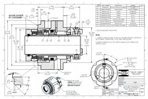
Single seal, cartridge design, independent from the direction of rotation, multi-spring. The seal acc. to EN ISO 21049 (API 682): type A, category 2 or 3, arrangement 1, configuration 1CW-FL (with a floating carbon throttle bushing).


 8613371530291