
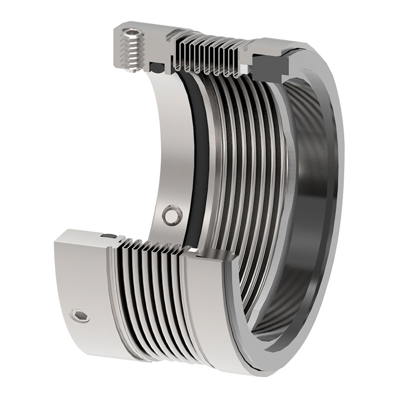
back to back mechanical seal in stock
In Part 2, we’re taking a closer look at the various rotary and stationary double seal arrangement options (configurations), and how to maximize their success.
A double seal is designed with two primary seals. These seals often use two rotating seal faces and two stationary seal faces. A fluid is provided between these two seals at a lower pressure than the sealed fluid (known as buffer fluid) or at a pressure higher than the sealed fluid (known as barrier fluid). The fluid provided to the dual seal allows the seal to survive in lethal, explosive, carcinogenic, hazardous, adhesive, or extremely viscous fluids.
A conventional double seal can be designed to seal the buffer or barrier fluid on the inside or outside diameter of the seal faces. Typically, the seal designer will place a softer, narrow face against a harder, wide seal face. The design intention is to enable the softer seal face to wear, while keeping the wider hard face from wearing in service. Once the narrow seal face has been worn away, the seal has reached the end of its suitable life.
Each configuration has its own strengths which are addressed below. Ultimately, it’s best to speak with a sealing specialist who can draw on a wealth of direct experience and implement according to your organizations’ expectations for reliability and environmental compliance.
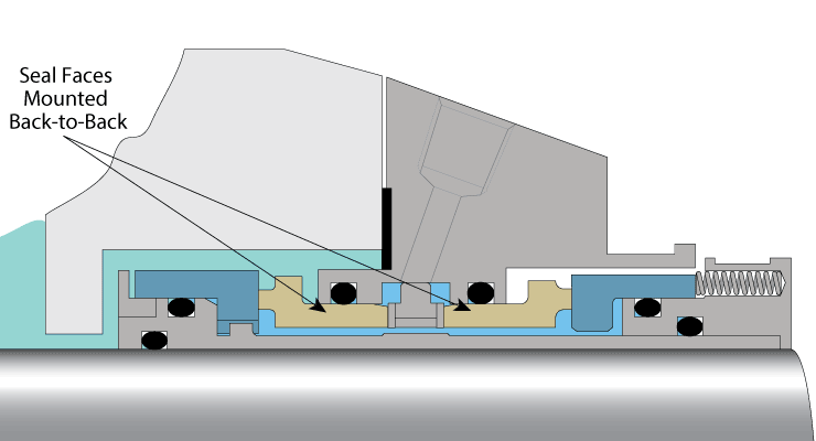
In this double seal configuration, two narrow seal faces are mounted back-to-back (opposing) to one another. This is the original concept of a dual seal —taking two component mechanical seals and placing them ‘back-to-back’ within the stuffing box. This configuration is used in most general applications.
The unbalanced back-to-back mechanical seal requires a barrier fluid pressure of 15 psig higher than the seal chamber pressure. The barrier fluid is being pressurized above the seal chamber pressure, so the outboard seal faces are carrying the greater load and should wear out or fail first. When this happens, the barrier pressure will be lost, causing the inboard faces to open. In other words – if the seal works correctly, both seals will fail at the same time. This is not very good back-up protection.
If this seal is a double balanced design, the fluid between the inboard and outboard seal faces can be higher (barrier) or lower (buffer) pressure than the seal chamber pressure. This means that if the barrier/buffer fluid is lost, both seals will remain closed and operate reliably.
In back-to-back arrangement (both unbalanced and balanced seal designs), the outboard seal faces almost always are rated for a lower pressure than the inboard seal faces. This is because the outboard seal faces are an outside seal configuration and the faces are exposed to tensile force. Ceramics are generally weaker in tension than compression, so their pressure limit is lower.
If the inboard seal fails first, the barrier fluid will leak into the process which will cause product dilution. This product dilution sometimes is not desirable for products that can not tolerate it.
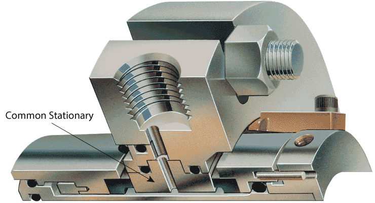
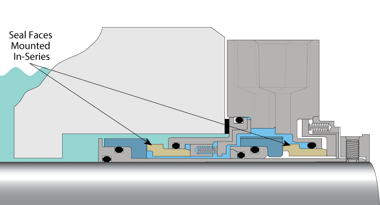
This configuration occurs when two sets of seal rings are identically orientated and mounted in-series. This configuration is often referred to as the “in-series seal face arrangement” or “face-to-back.” It is commonly used in dual seals.
In this arrangement, the seals position the barrier or buffer pressure on the outside diameter of the outboard face. The pressure acts to compress the outboard seal faces. This allows a higher barrier fluid pressure.
Face-to-face seals can be used when the equipment is space constrained to accommodate a back-to-back or tandem seal arrangements. In this configuration a portion of the seal is mounted in the seal chamber and the remainder is mounted outside of the seal chamber.
For successful seal life and reliability it is very important to have the right seal arrangement along with the right barrier/buffer fluid system. In upcoming blogs, we will discuss various seal environmental control plans available for double seals and how to select the best barrier / buffer fluid for good seal life to achieve maximum reliability.
Antim Parikh is a Special OEM Projects & Applications Support Manager at A.W.CHESTERTON for mechanical seal product line. He manages the group of mechanical seal applications engineers and OEM platform products/projects.
Antim has worked for the A.W. Chesterton Company for the last six years in the Mechanical Seal product line as Lead Applications Engineer. He has provided support to all field salespeople and customers on product recommendation and troubleshooting. He has also conducted numerous mechanical seal training classes for customers and distributor’s specialists to provide assistance to training group.
Antim holds degrees in Master of Science in Mechanical Engineering (Fluid Power) from CT, USA and Bachelor of Science in Mechanical Engineering from India.
The Safeseal Type SE1 is a customer-fitted (OEM standard) single, balanced component or cartridge seal designed for clean and lubricating fluids such as water, different types of oils, solvents and paper stock. The Type SE1 seal is designed especially for the Sulzer APP and APT pump series and Scan pump. The SE1 seal is easy to install and maintain. In spite of its simple design, SE1 is very advanced in its technical capabilities, including, for example, a patented thermal method for seal face holding and an elastic thrust ring.
This website is using a security service to protect itself from online attacks. The action you just performed triggered the security solution. There are several actions that could trigger this block including submitting a certain word or phrase, a SQL command or malformed data.

Dual cartridge seals, also referred to as double cartridge seals, are the answer for applications where a second level of protection is needed due to risks to the environment or operating equipment. Flexaseal offers a variety of models that are easy to install while also complying with environmental regulations and ANSI standards. A variety of configurations are available depending on the application and operating conditions.
In a back-to-back arrangement, the CarLife 299 cartridge seal continues to impress customers with its competitive price, field proven reliability, and large runout capability beyond industrial requirements, and has already been widely used for a broad range of applications across various industries.
As a paradigm in the design of the CarLife family, the CarLife 299 features part interchangeability between inboard and outboard seals. Moreover, besides similar construction and assembly procedure, the family shares major parts. More shared parts mean simpler maintenance process and inventory management. As a result, our CarLife customers are able to stock fewer inventory parts and pay much lower maintenance and inventory holding costs. And the more CarLife products they use, the more benefits they can gain from their cost-effective CarLife seals.

Removing the need for large volumes of flush water that can be required by mechanical seals and replacing the risk of sudden catastrophic failure with controlled, predictable performance.
The KlickFix system eliminates the need for the continual adjustment and tightening associated with compression packings, whilst the low friction seal lips also reduce potential shaft wear. The multiple sealing lips, which are a feature of the system, are safely stored until required and then can be rapidly deployed, preventing leakage and bringing plant back into service with minimal process interruption.

Pumping processes involving toxic or hazardous fluids that can’t risk leakage because of stringent environmental regulations require a double mechanical seal. Compared to a single mechanical seal, a double seal gives you significantly greater protection against leaks. With a double mechanical seal, you have an arrangement of two mechanical seals (a primary or inboard seal and a secondary or outboard seal) in series—back-to-back, tandem, or face-to-face. Each seal has a rotating (R) surface and a stationary (S) seal surface. These seals can be arranged in one of three patterns.
In a back-to-back arrangement, the stationary seal faces are positioned back-to-back with the rotating seal faces on the outside. The back-to-back arrangement is easy to install and used for many general pumping applications.
The tandem arrangement has the two pairs of seals mounted with the same orientation. This arrangement is preferred for toxic or hazardous applications because the outboard seal provides full pressure back-up, allowing the outboard seal to back up in the event of an inboard seal failure.
In the face-to-face arrangement, the rotating seal faces share a common stationary seal face. This arrangement is useful when equipment space is too constrained to permit back-to-back or tandem seal arrangements.
The American Petroleum Institute (API) Standard 682 classifies double mechanical seals into two configurations—pressurized and unpressurized. The pressurized arrangement has a barrier fluid delivered to the double mechanical seal by a seal support system. The barrier fluid is delivered at a higher pressure than the process fluid and must be chemically compatible with the process fluid as it will lubricate the inboard seal faces and mix with the process fluid. The unpressurized arrangement has a buffer fluid delivered to the double mechanical seal by a seal support system. The buffer fluid is delivered at a lower pressure than the process fluid.
The barrier and buffer fluids you use can be liquid or gas. They provide lubrication and help maintain the required operating temperature of the seal faces. The typical choices are water and water/glycol mixtures, low-viscosity petroleum or synthetic oils, kerosene, diesel, and nitrogen.
To gain a better understanding of the differences between the uses of barrier and buffer fluids, let’s look at two common API plans for double mechanical seals—API Plan 52 Buffer Fluid Seal Pot and API Plan 53A Barrier Fluid Seal Pot Pressurized by Nitrogen.
API Plan 52 takes buffer (unpressurized) fluid from a reservoir (seal pot), delivers it to the seal chamber, circulates it between the inboard and outboard seals using a pumping ring located driven by shaft rotation, then returns the fluid to the reservoir. In the event of an inboard seal failure, process fluid leaks into the seal chamber. When that occurs an increase in buffer fluid pressure and/or level alerts operators to the problem. The outboard seal, however, contains leakage until maintenance can replace the damaged seal.
This plan can include cooling coils in the reservoir to maintain the required buffer fluid temperature, visual or mechanical fluid level indicators, pressure and level transmitters, and connection to a collection system and buffer fluid replenishment source.
The overall design of this API plan for a double mechanical seal is relatively simple in comparison to other plans. Design decisions involving tubing size, length, geometry, type (carbon vs stainless steel), buffer fluid type, and volume of the buffer fluid reservoir are critical in maintaining the proper operating environment for the double seal. If you don’t have this expertise in-house, work with an experienced, local seal support system vendor to ensure the API Plan 52 is designed to meet your specific pumping requirements.
API Plan 53A is conceptually similar to API Plan 52 with the difference that the fluid being circulated between the double mechanical seals is under pressure. A pumping ring is used to circulate the fluid. The reservoir that contains the barrier fluid is pressurized by plant nitrogen. Reservoir pressure should be set a minimum of 20 to 25 psi (1.4 to 1.73 bar) above the maximum seal chamber pressure, allowing the barrier fluid to leak (and lubricate) across the inboard seal faces into the process fluid. For this reason, the barrier fluid must be chemically compatible with the process fluid.
Because barrier fluid is depleted as it moves across the inboard seal faces, it needs to be replenished. This can be done manually or automatically by way of a system that serves multiple pumps. API Plan 53A design options include reservoir type and volume, cooling coils, fluid level and pressure indicators, and transmitters to alert to level or pressure changes that indicate seal failure.
When you choose an API plan for a double mechanical seal, your primary decision is between a buffer or barrier plan. I’ve highlighted two of the API plans for double mechanical seals above to show the basic differences. There are multiple API plans for double mechanical seals to choose from—pressurization from bladder or piston accumulators, plant nitrogen delivered directly to the seal chamber, and custom-engineered external systems. Your choice will be determined by the process fluid and pumping conditions and the type of double mechanical seal your vendor recommends.
With this information in hand, it’s best to work with an experienced local seal support system vendor. They’ll be able to meet with you on-site to review the specifications for the pumping process, the pump, and the double mechanical seal. They’ll evaluate your existing infrastructure and its influence on seal support system design. Based on this information, they’ll then design the seal support system to meet the specific pumping requirements.
If you work with a global vendor like Swagelok, based on the design, we can quickly assemble and thoroughly test the API plan at our local facilities prior to delivery. We’re also conveniently available for follow-up consultations, on-site, remotely, or by way of a quick phone call.
For well over 50 years, Swagelok has worked closely with Northern California process industries to confidently choose the right API plans for pumping needs. Our locally based Field Engineers and certified technicians provide field verification of your seal support requirements, designs based on best practices gained from global experience.
To find out more about howSwagelok Northern California can help you choose the right API plan for double mechanical seals, as well as process and atmospheric side seals,contact our team today by calling
Morgan holds a B.S. in Mechanical Engineering from the University of California at Santa Barbara. He is certified in Section IX, Grab Sample Panel Configuration, and Mechanical Efficiency Program Specification (API 682). He is also well-versed in B31.3 Process Piping Code. Before joining Swagelok Northern California, he was a Manufacturing Engineer at Sierra Instruments, primarily focused on capillary thermal meters for the semiconductor industry (ASML).

Pump South maintains a sales force with 90+ years of combined experience in solving fluid handling applications. Pump South has consistently been presented with awards for sales achievements from various vendors, such as Top 10 Net Sales Worldwide for Versa-Matic AOD pumps/parts, Top 10 in Growth Percentage for Flowserve Sealing Technologies, as well as others.
At Pump South, you won"t talk to an automated system. A real person will answer the phone and get you directed to someone who can get you an answer right away. No waiting hours for a call back. Pump South not only provides quality pump and seal products, but we can assist with the troubleshooting process and provide recommendations for increased equipment reliability.
We offer same day shipment from our $1mm local inventory of pumps, parts, and mechanical seals at no additional charge. The products we distribute include centrifugal, gear, metering, and air diaphragm pumps, as well as pump/mixer mechanical seals. We stock an extensive inventory of pumps, parts, and mechanical seals and strive to ship products to meet your required delivery schedules. Please take a look at our products page to see a listing of many of the lines we represent.

ABSOLUTE SEALING. Resulting in less pumpage loss, cleaner facility environment, reduced fire hazard, no danger from fumes and no contamination of the fluid being handled.
NO RUBBING FRICTION BETWEEN SHAFT AND SEAL PARTS. Eliminate expensive shaft and sleeve replacement by replacing your old packing with new state-of-the-art U.S. Seal Mfg. Mechanical Seals.
GREATER FLEXIBILITY OF SEALS MEANS LONGER SERVICE LIFE. Seals have more flexibility than packing and are able to compensate for shaft whip, axial and radial end play, as well as vibration and wear of the sealing faces.
EXTREME FLAT SURFACES OF MATING FACES. Care is taken to furnish precision lapped sealing surfaces with a flatness within three light bands maintaining the necessary face film lubrication.
MATERIALS OF CONSTRUCTION. TFE, AFLAS®, EPR and VITON® materials are available for those applications where NEOPRENE and BUNA are not compatible with the process fluid. Metal parts are normally made of brass, plated steel or stainless steel, but other alloys, such as Monel® or Hastelloy® can be supplied. Seat materials are available in a wide selection.

The rotating shaft of a centrifugal pump penetrates the back end of a pump casing through a stuffing box or seal chamber. The primary purpose of a mechanical seal in a centrifugal pump is to prevent fluid from leaking to the atmosphere along this rotating shaft. Selection of the right mechanical seal for each pump application is critical when considering safety and reliability. Mechanical seal failure is typically one of the primary reasons why pumps fail. In this guide, the experts at PumpWorks will show you the steps to install a mechanical seal in your centrifugal pump with minimal downtime.
A mechanical seal requires two extremely smooth and flat (lapped) seal faces in contact, one rotating with the shaft and the other stationary with the casing. These seal faces are sealed to their appropriate holders through the use of secondary seals (o-rings or gaskets). The faces are mechanically energized and flexible so that they can be placed into contact and move to make up for static and dynamic misalignments as well as wear. The seal faces require lubrication from the fluid and break down this fluid as it tries to escape through the seal faces, resulting in slight vapor release. All mechanical seals leak…vapor…when selected and sized correctly.
You may be wondering how long the mechanical seal installation procedure will take. By following the 10 simple steps listed below, you’ll have the job done in no time.
The first step is to power off the centrifugal motor so that it is not in motion. Shut down the main power supply and double-check that there is no chance of the machine starting up again. Once this is done, it’s time to get to work!
If your pump is a ‘back pull-out’ design, remove the spacer element in the pump coupling. Then remove the casing bolts and slide the remainder of the pump away from the casing. You are now able to access the mechanical seal without having to disconnect the casing from the inlet and outlet piping. If the pump is not a ‘back pull-out’ design, you will need to disconnect the complete pump after disconnecting the coupling between the pump and motor shaft. If the pump is a close coupled design (the pump uses the shaft of the motor as its shaft and the motor directly bolts onto the back of the pump), you will need to remove the entire pump/motor. Remove the casing bolts and remove the casing.
The mechanical seal is located behind the impeller on the pump shaft. Impellers are either screwed onto the shaft or held in place via a bolt. To remove the screwed-on impeller from the shaft, use a wrench to hold the shaft in place and rotate the impeller clockwise until it is completely unscrewed. To remove a bolted impeller, hold the shaft in place and remove the bolt.
You can now directly access both the rotary and stationary seal parts. The rotary parts are typically held in place along the shaft using set screws. Remove the set screw and slide off the rotary seal parts. Remove the stationary part of the seal from the casing or seal chamber bore.
Now it’s time to place a new mechanical seal onto the shaft. Carefully slide the replacement seal parts along the shaft. Using a new o-ring or gasket material, press the stationary part into the casing or seal chamber bore. Follow the instructions for setting the rotary portion back onto the shaft correctly. This is a crucial step.
CAUTION: Always install mechanical seals in a clean working space. Don’t touch the front of the seal faces as it is susceptible to body oils and may not function properly if compromised. Keep the seal in its packaging until it’s time to install.
Use your wrench to hold the shaft in place while you screw the impeller onto the pump’s shaft using a new impeller o-ring or gasket. Or use the impeller bolt and a new o-ring or gasket to attach the impeller to the end of the shaft.
For back pull-out designs, slide the back pull-out assembly up against the installed casing and bolt it in place. Checking pump alignment will be necessary after step 9 below. For close coupled or non-back pull-out designs, reinstall the casing using the casing bolts. In all cases, torque the casing bolts in accordance with the pump Installation, Operation, and Maintenance (IOM) manual.
For back pull-out designs, the only steps remaining are to reinstall the spacer element to the existing coupling hubs along the pump and motor shaft, and make sure the mounting feet of the back pull-out assembly are bolted back into place on the pump baseplate. Realign the pump and motor. For close-coupled pumps, place the pump back and reconnect the inlet and outlet piping. For non-back pull-out pump and motor designs, replace the pump on the baseplate, reconnect the inlet and outlet piping, re-bolt the pump to the baseplate, reconnect the coupling and then realign the pump and motor.
Make sure you have refilled the pump casing by opening the inlet and outlet isolation valves. Some pump designs will require venting, so refer to your pump IOM. Before starting the pump, it is always a good idea to re-verify the rotation of the motor to make sure it is correct. This is done before reconnecting the pump and motor coupling. Bump the motor and verify rotation. Then reconnect the coupling, and the pump is ready to start.
Always review safety precautions found in the pump IOM. Always use the Pump IOM when working on any pump. Install the mechanical seals using the specific instructions from the mechanical seal manufacturer. Lastly, always make sure the pump and motor are realigned within 001” – 002”. Misalignment will cause premature mechanical seal failure.
PumpWorks is the go-to company for all your mechanical seal installation needs. Our pump manufacturing company offers over 30 years of experience in the troubleshooting, selection, application, and repair of mechanical seals. We serve a wide range of process industries such as petroleum refining, chemical, food and beverage, water and wastewater, power, and more.

Double mechanical cartridge seals have a barrier fluid between both pair of seal faces. One pair is located at the product side, the other pair is located on the atmospherically side. In-between is the streamed barrier fluid to cool the seal faces and to ensure that no contamination of the environment will appear. Several plans and methods are used in industry to seal different fluids, while realizing a long run time. These plans are advised by the American petroleum institute, called API. Most plans reconsider extra systems which are built and manufactured by STB.
Power machines that have a rotating shaft, such as pumps and compressors, are generally known as “rotating machines.” Mechanical seals are a type of packing installed on the power transmitting shaft of a rotating machine. They are used in various applications ranging from automobiles, ships, rockets and industrial plant equipment, to residential devices.
Mechanical seals are intended to prevent the fluid (water or oil) used by a machine from leaking to the external environment (the atmosphere or a body of water). This role of mechanical seals contributes to the prevention of environmental contamination, energy saving through improved machine operating efficiency, and machine safety.
Shown below is a sectional view of a rotating machine that requires the installation of a mechanical seal. This machine has a large vessel and a rotating shaft at the center of the vessel (e.g., a mixer). The illustration shows the consequences of cases with and without a mechanical seal.
If the aim is solely to prevent leakage from the machine, it is effective to use a seal material known as gland packing on the shaft. However, a gland packing tightly wound around the shaft hinders the motion of the shaft, resulting in shaft wear and therefore requiring a lubricant during use.
Separate rings are installed on the shaft and on the machine housing to allow minimal leakage of the liquid used by the machine without affecting the rotating force of the shaft.
To ensure this, each part is fabricated according to a precise design. Mechanical seals prevent leakage even with hazardous substances that are difficult to mechanically handle or under harsh conditions of high pressure and high rotating speed.
A mechanical seal is installed on the impeller rotating shaft. This prevents the liquid from leaking through the clearance between the pump body and the shaft.
The rotary ring rotates with the shaft. The stationary and rotary rings rub against each other ensuring a clearance in the order of micrometers maintained between them. Where they rub against each other, they are referred to as “face materials.”
The face materials where the stationary ring and the rotary ring rub against each other are the most important portions as a barrier to the fluid. If the clearance is too small, the friction increases, hindering the shaft motion or resulting in seal breakage. Conversely, if the clearance is too large, the liquid will leak. Consequently, it is necessary to control the clearance in the order of micrometers to prevent leakage, but at the same time ensuring lubrication by the fluid, thereby reducing the sliding torque and avoiding hindrance to the machines’ rotation.
The mechanical seal technology is a sum of mechanical engineering and physical property technology due to the above-mentioned functions and applications. More specifically, the core of the mechanical seal technology is the tribology (friction, wear and lubrication) technology used to control the surfaces where the stationary and rotary rings rub (slide) against each other.
Mechanical seals with improved functionality will not only prevent the liquid or gas handled by a machine from leaking to the outside, but also improve machine operating efficiency, thereby helping achieve energy saving and prevent environmental contamination. Moreover, in some cases, rotating machines handle media that, in the case of leakage, can lead to a dangerous accident. Therefore, mechanical seals are required to be highly reliable through manufacturing backed by solid engineering expertise.
These functions and roles will make mechanical seals increasingly important functional parts in the future. Their further technical innovation is anticipated. To positively respond to these expectations, Eagle Industry is working on technical research and development every day.
The mechanical seal technology was fundamentally established in the 1960s. Thereafter, it has been making significant progress by introducing various leading-edge technologies, and innovative mechanical seals created from the above advanced technology are continuously being put to practical use.
To meet the demands of the market sufficiently, an applicable range of the “pressure” and “rotation speed” of mechanical seals has been considerably extended since the beginning of the 2000s. This is due to advancing of the tribology technology such as to enhance a function of the sliding materials (e.g., composite material composition, coating technology) and/or a performance of the sliding surfaces based on the fluid lubrication theory (e.g., non-contact mechanical seal, surface textured mechanical seal). These advanced technologies are sustained by improvement in the element technology of numerical analysis, processing/production, physical property/composition analysis, measurement, verification test, and so on.
Source: “Current status and future prospects of a wind/hydraulic machinery industry from 2021 to 2025”, The Japan Society of Industrial Machinery Manufacturers (2021).


 8613371530291