
balanced vs unbalanced mechanical seal factory

A. A balanced seal is a mechanical seal configuration in which the fluid closing forces on the seal faces have been modified through seal design. Seal balance, or balance ratio of a mechanical seal, is simply the ratio of two geometric areas. These areas are called the closing area (Ac) and the opening area (Ao). The closing area is different when pressure is on the outer diameter of the seal than when the pressure is on the inner diameter. When the pressure is on the outer diameter, the closing area is from the seal face outer diameter down to the lowest point, where the secondary seal rests against the shaft or sleeve. When the pressure is on the inner diameter, the closing area is from the highest point, where the secondary seal rests against the primary ring counter bore, down to the sleeve diameter.
The opening force is always the area of the sealing faces. The balance ratio is then Ac/Ao. A seal with a balance ratio less than 100 percent is called a balanced seal. A seal with a balance ratio greater than 100 percent is called an unbalanced seal. Most balanced seals have a balance ratio between 60 and 90 percent. Most unbalanced seals have a balance ratio between 110 and 160 percent.
Pusher seals normally require a step in the shaft/sleeve or internal hardware to achieve a balanced design. Metal bellows seals do not require this step. The balance diameter, or mean effective diameter (MED), of metal bellows seals is located near the middle of the convolution. When pressure is applied to the outer diameter of the seal, the MED shifts downward, lowering seal balance. The opposite is true when the seal is subject to internal pressure. The rate of change in the balance depends on the face width and the bellows leaflet design.
Pusher seals can be designed to withstand pressure from either direction. This is accomplished by trapping the O-ring between two diameters as shown in Figure 4.1. The cavity must be long enough to allow the O-ring to move, allowing pressure to act on the primary ring. These designs allow the seal to withstand system upsets.

Mechanical seals have classified several types. In this article, we will see the basic classification of mechanical seal that is the “Mechanical Seal – Balanced and Unbalanced Type”.
The pressure in any stuffing box acts equally in all directions and forces the primary ring against the mating ring. The force (F) acts only on the diameter (Do) across the seal face, it acts as a closing force on the seal faces.
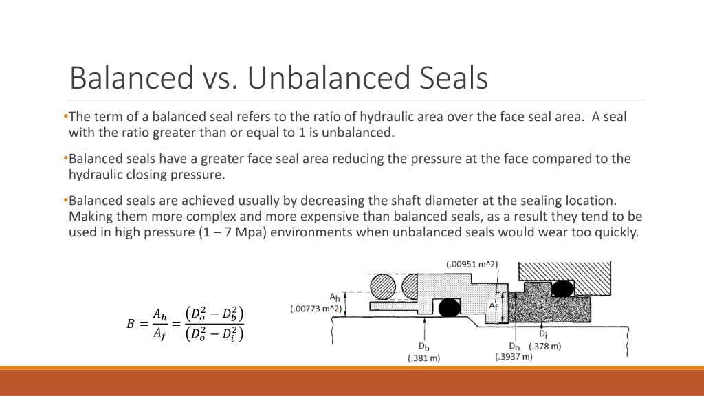
To relieve the force at the seal faces, the diameter of the shoulder on a sleeve or the seal hardware is decreased. Thereby the seal face pressure can be lowered. This is called seal balancing.
A seal without a shoulder in the design is an unbalanced seal. A balanced seal is designed to operate with a shoulder. Only metal bellows seal is a balanced seal that does not require a shoulder.
Virtually all mechanical seals are available in either unbalanced ( Ref. Figure) or balanced versions. The term “unbalanced” is used when the stuffing box pressure times the area exposed to the pumped fluid (closing force), acting to close the seal faces, is greater than the average pressure between the seal faces (pressure gradient)times the area of contact between the faces. In other words, unbalanced mechanical seal exhibit net hydraulic closing forces which are generated by the actual pressures to be sealed.
For example, if there were a stuffing box pressure of 50 psig (3.4barg), the spring load would have to be added. Hence, the “face load” or closing force on the faces would be even higher than 50 psig times the face area. This, of course, limits the pressure sealing capacity of an unbalanced seal.
Unbalanced seals are often more stable than balanced seals when subjected to vibration, misalignment and cavitation. The disadvantage is their relatively low-pressure limit. If the closing force exerted on the seal faces exceeds the pressure limit, the lubricating film between the faces is squeezed out and the highly loaded dry running seal fails.
The balanced seal has the same opening (face) area as the unbalanced seal, but the closing area has been reduced about the face area. Because force equals pressure times area, reducing the closing area reduces the closing force. Consequently, less heat is generated and the seal generally has a longer life.
To simplify the explanation, balancing mechanical seal involves a small design change which reduces the hydraulic forces acting to close the seal faces. Balanced seals have higher pressure limits, lower seal face loading, and generate less heat. They are better able to handle liquids with low lubricity and high vapour pressures. This would include light hydrocarbons. Because seal designs vary from manufacturer to manufacturer and from application to application, it is not possible to standardize on either configurations or materials that cover all conceivable services. Available basic designs have variations that were often developed to meet specific applications. Each seal design has its own strengths and weaknesses.
Nowadays most of the seal manufactures are used only balanced mechanical seal. In some special mechanical seals (ie., engineered seals) are designed with unbalanced mechanical seal.
Balanced mechanical seals are more preferred than unbalanced mechanical seals. Seal balance can range from 0.65 to 1.35, depending on operating conditions.

The balance of a seal refers to the distribution of load across the seal faces. If there is too much load on the seal faces, it can lead to a leakage of fluids from within the seal which essentially renders the seal useless. Moreover, the liquid film in between the seal rings runs the risk of vaporising.
This can result in higher wear and tear off the seal, shortening its life span. Seal balancing is therefore necessary to avoid disasters and to also elongate the life of a seal.
A balanced seal has a higher pressure limit. This means that they have a larger capacity for pressure and they also produce less heat. They can handle liquids that have a low lubricity better than unbalanced seals.
On the other hand, unbalanced seals are typically much more stable than their balanced counterparts as far as vibration, cavitation and misalignment are concerned.
The only major drawback that an unbalanced seal presents is a low pressure limit. If they are put under even slightly more pressure than they can take, the liquid film will quickly vaporise and will cause the running seal to run dry and thus fail.

The balance ratio of a mechanical seal is an area ratio and is related to the seal face load. Balance ratio is defined as the ratio of the closing area to the opening area. Seals with a balance ratio > 1 are "unbalanced"; ratios of < 1 are considered "balanced". Seals are balanced to decrease friction and wear, so you will usually move to a balanced seal at pressures of 250 psid and above (although you can use them at lower pressures as well). Unbalanced seals will be used up to 250 psid. The theory becomes more complex when you talk about metal bellows style mechanical seals; in those designs the balance ratio will increase at higher pressures primarily due to the bellows plate geometry. Visually if you were to look at the primary face of an unbalanced pusher style seal vs. a balanced pusher style seal you would notice a "step" in the face geometry (reducing the closing area and changing the balance ratio).
In theory, the lower the balance ratio, the lower the fluid film temperature, the longer the seal life. In practice, leakage control can sometimes be sacrificed and the faces may become unstable depending on if the fluid is volatile (vaporizing), or if any other face distortions occur. In general, review of the application with your seal vendor is always recommended. If you are adhering to API 682; then balanced seals are your only options due to the nature of the services. The attached is a very rough representation of what I just said. It depicts a single set of seal faces pressurized from the OD: the balance ratio calculations will become more complicated when you discuss OD vs. ID pressurizations particularly in dual pressurized seals. Hope this helps.

There are various types and arrangement of the mechanical seals being used for the centrifugal pumps. Some of the commonly used ones are described below:
The pusher type of mechanical seals move axially along the rotating shaft or the sleeve to maintain the contact with the faces of the seal. This feature of these seals helps compensate for the wearing that may occur at the seal face, and wobbling due to misalignment. The pusher types of mechanical seals are used commonly, are less expensive and are easily available in the market in wide range of sizes and designs. The only disadvantage of these seals is that they tend to hang up and sometimes there is fretting of the shaft.
The unbalanced types of mechanical seals are used under drastic conditions where there are vibrations, misalignment of the shaft, and the problem of the cavitation of the fluid. These mechanical seals are inexpensive, allow lesser leakage of the fluid and are highly stable. However, these seals can operate only under low pressure range and if the force of the fluid exceeds certain limits the lubricating film between the faces squeezes out and the seal fails.
As the name suggests, the non-pusher or bellow type of mechanical seals don’t have to be moved axially to maintain their contact with the faces. These seals can work under low temperature and high pressure applications. The bellows used in these seals should be upgraded so that they can work under the corrosive environments.
The balanced mechanical seals have the ability to sustain higher pressures across the faces and they generate lesser heat thus they are suitable for handling liquids that have low lubricating capacity and hydrocarbons that have high vapor pressure.
The major advantage of the cartridge seals is that they don’t require complicated setting during the installation as required by the conventional seal. This helps reducing errors associated with seal setting and eventually also reduces the maintenance required.
There are various types and arrangements of the mechanical seals available in the market. It is very important to use appropriate mechanical seal for the required application. If the incorrect mechanical seal is selected there are chances that the fluid would start leaking from the pump and the very purpose of installing the expensive mechanical seal will be destroyed. In addition there would be loss of time, manpower, resources and also some safety hazards.
1) Liquid or fluid to be pumped: The first and the most important factor to consider while selecting the mechanical seal for the centrifugal pump is the liquid or the fluid to be pumped. If ordinary liquid like water is to be pumped, then conventional mechanical seal with ordinary materials can be selected. In fact in many water pumps ordinary glands are used as the sealants since any leakage of water to the external atmosphere is not dangerous. But you can always see the water dripping from the pumps using ordinary glands.
If the pump has to handle corrosive liquids like acids, it is very important to select corrosion resistant materials for the mechanical seals. Some of these materials can be stainless steel, bronze or hastelloy. The mechanical seals also comprise of the mating surfaces and these should also be made up of corrosion and wear resistant materials like ceramic, silicon or tungsten carbide, carbon etc. For the corrosive environments the materials for the stationary parts of the mechanical seal can be Teflon, Buna, EPR or Viton.
2) Pressure of the liquid: The liquid enters the pump at certain pressure and the pump has to increase its pressure to certain level so that it reaches certain height. The total pressure on the seal decides whether one should opt for the balanced seal or the unbalanced type of seal.
3) Temperature of the liquid: Some pumps handle liquids at high temperatures and others handle the liquids at low temperature. The materials and mating surfaces used in mechanical seals should be able to sustain the temperature of the fluid.
4) Nature of fluid: The liquids to be handled by the pump may be having ordinary flow, but there can also be chemical solutions that have high viscosity and slow flow, there can be precipitates, there can be abrasive liquids and so on. These types of fluids usually cause more wear and tear of the parts of the mechanical seals and in such cases it is advisable to use double seals.
5) Safety and Environmental concerns: The safety of human being handling the pump is of prime importance so are the permissible emission standards. To be on the safer side it is always better to used double seals that work as the better sealants and are more reliable.
Centrifugal pumps are one of the most extensively used pumps in municipal and complex industrial applications. However, a proper sealing arrangement is imperative for these pumps to prevent fluid leakage and protect the pump’s inside from contaminants in the atmosphere. Mechanical seals are preferred for sealing the pump as they require less maintenance and are much more durable than packing seals.
There are a variety of options in the market when it comes to mechanical seal systems. Before illustrating the types of mechanical seals for centrifugal pumps, here are four key considerations when choosing the appropriate seal system.
Consider the type of fluid that will be pumped and how it will affect the seal system design—factors such as lubricity, volatility, corrosive properties, and cleanliness matter the most.
Make a choice depending on the pressure exerted on the seal face. For instance, unbalanced seals are suitable for low-pressure applications, while balanced seals are appropriate in high-pressure conditions.
Temperature considerations will help determine whether you need to choose a pump with heat-sensitive components. For example, balanced seals sustain high temperatures better than their unbalanced counterparts.
These types of mechanical seals are typically low in cost and used for more generalized purposes. However, installing and adjusting standard component seals is time-consuming and requires a fair amount of operational skills. In addition, as they are composed of separate dynamic and stationary components, incorrect installation remains the major cause of errors.
Cartridge type mechanical seals are easy to install and ensure high performance. They are a one-piece unit incorporating all sealing components into a single assembly. Cartridge seals provide substantial maintenance advantages compared to other seal types while reducing installation time and the risk of assembly errors.
Pusher seals rotate along the shaft or sleeve to maintain contact with the faces of the seal to reduce wearing and wobbling caused by any misalignment. They are less expensive and come in different sizes and designs. The only drawback is that the elastomer is subject to wear.Non-pusher type seals maintain contact with the faces without rotating axially. They function under low temperatures and high pressures. However, the bellows used in these seals must be replaced frequently to work in corrosive environments.
Balanced mechanical seals work at high operational pressures while generating lesser heat. They are suitable for handling low lubrication liquids and high vapor pressure. Balanced seals increase seal life by reducing the closing force.Unbalanced mechanical seals are a more economical alternative that works for low/medium pressure applications. They are highly stable and still work in conditions where there are vibrations, shaft misalignments, or fluid cavitations.
Balanced and unbalanced type The specific pressure (the force per unit area) of the end face of the friction pair and the pressure of the medium to be sealed can be divided into balanced and unbalanced types.
Non-equilibrium type: The effective area of the medium acting on the moving ring (the area where the offset pressure cancels each other) is equal to or greater than the contact area of the moving and static ring. The specific pressure of the end face increases or decreases proportionally with the pressure of the sealing medium, so that when the medium pressure is high, a large specific pressure is generated on the end surface, which accelerates the wear of the friction surface, generates heat, and destroys the liquid film on the end surface to form dry friction. Generally, the unbalanced medium pressure does not exceed 686 KPA.
Balanced type: When the medium pressure is high, it is necessary to try to eliminate the effect of a part of the pressure on the friction surface from the sealing structure. This type of seal is called a balanced mechanical seal. In this seal, the effective area B of the medium acting on the dynamic damage is smaller than the contact area A of the end face of the dynamic static ring. The specific pressure on the sealing end face can be controlled by itself, and the increase or decrease of the medium pressure has little effect on the specific pressure of the end face.

An end face mechanical seal is a device intended to prevent or minimize leakage from a vessel through the clearance around a rotating shaft entering that vessel. Perhaps the most common example is the end face mechanical seal used in the water pump of an automobile engine. Most pumps used in petroleum refineries, chemical plant and pipelines also use end face mechanical seals.
The simplest possible mechanical end face seal consists of a shoulder on a rotating shaft which rubs against a stationary case. This concept is shown in Figure 3.
As with packing or any bearing material, lubrication and cooling are required to prevent heat buildup and wear. Hydraulic pressure tends to force fluid between the faces and provide a lubricating film but the face separation must be kept very small to minimize leakage. Cooling is provided by the surrounding liquid. The conceptual design shown in Figure 3 is very simple, but it demonstrates the basic principle of the end face mechanical seals. Of course, it has functional drawbacks which must be addressed.
Seal face leakage is governed by many variables, but the dominant variable is face separation. A variation of a few micro-inches (millionths of an inch) in the face separation can cause significant changes in leakage. Unfortunately, shaft movement can amount to several thousandths of an inch.
A practical approach to overcoming shaft movement is to mount one of the seal faces in a flexible manner so that it can move axially. Obviously a desirable feature, this flexibility is a prerequisite for effective seal design.
Figure 4 shows an improved seal as compared to Figure 3. In Figure 4, The sealing shoulder on the shaft has been removed and replaced with a component which is not permanently attached to the shaft. This component is called the primary ring. The “face” of the primary ring rubs against the mating ring. Since the primary ring and the shaft are two separate parts, an additional sealing device must be used to prevent leakage between the shaft and primary ring. The flexibly mounted primary ring can compensate for the small variations in movement on the axial plane. It can also adjust for seal face wear. Figure 4 is a very simple mechanical seal but it illustrates the concept used by the majority of mechanical seals. Of course, some additional components are required to preload the faces, transmit torque and provide ease of installation.
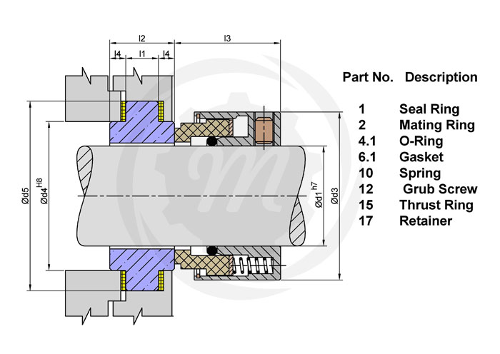
Figure 5 shows a more complete mechanical seal including a replaceable mating ring, “O-ring” gaskets, springs, setscrews and various other hardware. As will be seen later, the design of these components may vary considerably according to the required service for the seal. In addition, the assembled components themselves may be arranged and oriented in various ways to accomplish varying degrees of sealing, reliability and redundancy.
In a mechanical seal, the primary leakage path is between the seal faces. Naturally, increasing the face separation increases the leakage. In fact, as will be shown later, doubling the face separation can increase the leakage rate by a factor of eight! This relationship between leakage and face separation provides a powerful incentive for minimizing face separation. In modern mechanical seals, face separations are so small (on the order of a few microns) that the leakage rate is affected by the surface roughness. The effective face separation is a combination of the surface roughness of the two mating parts and the fluid film thickness. This concept is illustrated in Figure 6. The seal manufacturer can control the initial surface finish by lapping and polishing. A typical seal face is flat to within 23 millionths of an inch. This degree of flatness is so small that refracted light rays must be used to measure it. The fluid film is established during initial start-up of the seal by hydraulic forces.
The principle of establishing a fluid film is essential to all seal designs. Most mechanical seals are designed to operate in liquids; these seals require a liquid film. Designing a seal to operate on a gas film is much more complex. Whether the film is gas or liquid, it reduces the gross contact between the rotating component and the stationary component. It also provides lubrication to reduce friction and wear. Without a stable fluid film, gross rubbing contact could damage the faces.
Mechanical seals may be classified by their design features and the arrangement of those features. The Design category includes the details and features incorporated into a single primary ring/mating ring pair. The Arrangement category includes the orientation and combination of the primary ring/mating ring pair. Figure 7 illustrates the classification of mechanical seals.
The Design classification considers the details which enter into the features of these components. Some examples of these features are balance, face treatment, rotating element, springs, secondary sealing elements and drive mechanism. In general, these design features are not completely independent; that is, emphasis of a particular feature may also influence other features. For example, selection of a particular secondary sealing element may influence the shape of the primary ring.
By definition, the primary ring is the flexible member of the mechanical seal. The design of the primary ring must allow for minimizing distortion and maximizing heat transfer while considering the secondary sealing element, drive mechanism, spring and ease of assembly. Many primary rings contain the seal face diameters, although this is not a requirement of the primary ring. The primary ring always contains the balance diameter.
Balance. The term “balance” is frequently referred to as the relationship of hydraulic forces on a seal but it is actually a geometric ratio. Balance ratio is defined as the ratio of the hydraulic closing area to the hydraulic opening area. This ratio is customarily expressed in a percentage.
Figure 8 illustrates the concept of balance. In a seal, hydraulic pressure acts on the back of the primary ring; the resulting force pushes the faces together. This force is called the closing force and this area the closing area. Similarly, any pressure between the seal faces creates an opening force which tends to separate the faces. Therefore, the face area is also called the opening area. The balance ratio is simply the ratio of the closing area to the opening area.
As shown in Figure 8, the area above the seal face outside diameter is disregarded when the closing area is computed. This area is not considered because the pressure is the same all around it; consequently the contribution of the resultant of the hydraulic forces on this area is zero.
When the closing area is reduced, the closing force is reduced proportionally; this feature can be used to advantage when designing a seal. However, for a seal shape such as shown in Figure 8, the closing area will always be greater than the opening area. In order to make the closing area less than the opening area, the shape can be changed as shown in Figure 9.
The seal shown in Figure 8 is said to be an “unbalanced” seal. Its balance ratio is greater than 100% because of the necessary clearance underneath the mating ring. Typical balance ratios for unbalanced seals range from 120 to 150%. The seal shown in Figure 9 is said to be a “balanced” seal; its balance ratio is less than 100%. The balance ratio of “balanced” seals is typically from 65% to 90%.
The distinction between “balanced” seals and “unbalanced” seals is simply that balanced seals have a balance ratio less than 100%. A seal with 99% balance ratio is balanced, a seal with 101% balance ratio is unbalanced.
For a given pressure, balanced seals have less face load than unbalanced seals. Therefore, balanced seals are normally used in higher pressures than unbalanced seals.
Primary ring shape.The shape of the primary ring may vary considerably according to the incorporation of various design features. In fact, the shape of the primary ring is often the most distinct identifying characteristic of a seal. Figure 10 shows four examples of typical primary ring shapes.
Figure 10a represents a primary ring associated with elastomeric bellows seals. This primary ring has been optimized to take advantage of the elastomeric bellows and a large, single spring.
Figure 10b represents a primary ring with an inserted seal face. Insert faces must be designed with care because temperature differentials can cause differential expansion between the adaptor and the primary ring. Insert designs can also have problems associated with mechanical stress and distortion.
Figure 10c and 10d show how the shape of the primary ring is influenced by the secondary sealing element. Figure 10c is a primary ring designed to work with a wedge. Figure 10d is designed to work with an O-ring. Also, Figure 10c shows an unbalanced shape while Figure 10d is a balanced shape.
Face Treatment.The most common seal face design is a plain, flat surface but there are many special treatments designed for specific applications. Figure 11 shows some of the more common face treatments. The plain, flat face is most common. In general, face treatments are a means of modifying the pressure distribution between the seal faces. The most common objective is to increase the opening force and thereby reduce the magnitude of the mechanical contact. Face treatments may be considered to produce hydrostatic or hydrodynamic forces.
Rotating Element. Although most illustrations have shown the primary ring to be rotating with the shaft, either the primary ring or the mating ring may be used as the rotating element. Seals with rotating primary rings are said to be “rotating” seals; seals with stationary primary rings are said to be “stationary” seals. Because the springs are always associated with the primary rings, sometimes the distinction is made as “rotating springs” versus “stationary springs”.
For convenience, rotating seals are used in most equipment. Pump shafts are already made of a comparatively high grade material and manufactured to close tolerances. This makes pump shafts well suited for rotating seal applications. Assembly of rotating seals can generally be done directly on the shaft or by using a relatively simple sleeves. Figures 5, 8 and 9 all show rotating seals with stationary mating rings.
Stationary seals have some advantages over rotating seals. In small, mass produced seals for modest services, the entire seal may be placed in a package which minimizes shaft and housing requirements for the equipment. Figure 13 shows a low cost stationary seal. Stationary seals are also used to advantage in large sizes or at high rotational speeds. Above 5,000 to 6,000 fpm, a rotating primary ring (which is flexible, by definition) may require dynamic balancing (for rotational imbalance) in order to operate in a stable mode. A stationary primary ring does not require this balancing. On the other hand, the stationary seal does require a close bore tolerance. This close bore tolerance is usually a second manufacturing operation on most equipment. Stationary seals sometimes incorporate special design features such as auxiliary liners, sleeves or adapters to help retain the mechanical advantages of the seal. Figure 14 shows a stationary metal bellows seal used in high temperature centrifugal pumps.
By definition, the mating ring is the non-flexible member of the mechanical seal. The design of the mating ring must allow for minimizing distortion and maximizing heat transfer while considering ease of assembly and the static secondary sealing element. The mating ring can contain the seal face diameters, although this is not a requirement of the mating ring. To minimize primary ring motion, the mating ring must be mounted solidly and should form a perpendicular plane for the primary ring to run against. Figure 15 shows some typical mating rings.
Floating. Figure 15d is the floating ring type. This design offers the flexibility of using teflon, grafoil, or an O-ring (Figure 15c) for the secondary sealing item. If teflon or grafoil is used, a pin should be added to prevent rotation due to the low coefficient of friction of these materials.
The secondary sealing elements are gaskets which provide sealing between the primary ring and shaft (or housing) and the mating ring and shaft (or housing). They are called secondary sealing elements because their leakage path should be secondary to the seal face leakage. Loading by hydraulics or mechanical force makes the secondary seal tight in its confined area. The secondary sealing element for the mating ring is always static axially (although it may be rotating). Secondary sealing elements for the primary ring are described as being either pusher or non-pusher in the axial direction. The term pusher is applied to secondary seals that must be pushed back and forth by the movement of the shaft or primary ring. A non-pusher secondary seal is a static seal for the primary ring.
Pusher type secondary seals have the disadvantage of damaging the surface to which they must seal. This damage, called fretting, is caused by the cyclic movement of the secondary sealing element as the shaft rotates. In contrast to the pusher design, a non-pusher secondary sealing element could not cause any fretting.
On the other hand, this rubbing and dragging effect is also an advantage of the pusher design because it adds damping and therefore stability to the seal. This damping can make a significant difference in performance for some services.
Figure 16 shows examples of pusher, non-pusher and static secondary seals. The pusher design may use O-rings, wedges, etc. The non-pusher is always some sort of bellows with a static section. Mating rings use various static gasketing and O-ring designs.
Bellows. Figure 16a is a full convolution elastomeric bellows. It offers the greatest possible flexibility to the front section of the primary ring. The front section of this bellows has minimum contact with the shaft or sleeve, thus minimizing wear and hang-up. The large tail section provides a considerable sealing area to compensate for imperfections in the shaft. There are also are variations of the full convolution design that use a half convolution. Its ability to accept axial motion is reduced, due to the one-half convolution design.
Figure 16b is a bellows made out of teflon or glass-filled teflon combinations. This seal which is designed for the extremes of corrosive environments, provides the advantages of the non- contacting bellows convolution. Because it is made out of teflon, support rings or a drive collar is required to attach the tail section or the bellows to the shaft. Due to the requirements of flexibility, the convolutions must be considerably larger in cross-section than the typical elastomeric bellows design.
Figure 16c is an all-metal bellows style seal. It has the inherent advantage of flexibility associated with bellows design for high temperature applications. Due to its all-metal construction, it offers considerable freedom of design since it is not restricted to the temperature and chemical limits of elastomers. Metal bellows are constructed of individually welded metal leaves approximately .004/.012 thick. A large number of leaves are required to provide the maximum amount of flexibility associated with other styles of bellows seals. The mechanical closing force that is provided by the spring on other seal designs is accomplished by stressing the bellows from free height in this design. Metal bellows seals are inherently balanced because of the manner in which the bellows becomes distorted when pressurized.
“V” Rings, “U” Cups and Wedges. Figure 16d is a wedge. Wedges are typically made of TFE material. They are considerably more flexible than the “V” ring or U-cup arrangement because they operate on the ball-and socket principal. Special manufacturing fits are not a requirement for wedges because of the shallow angle of contact between the primary ring and the shaft. However, it does require a polished surface for effective sealing (32 rms with polish).
In addition to wedges, there are U cups and V rings. Their construction as a secondary seal offers limited amounts of flexibility and requires extremely close tolerances on the cross-section fits. The “V” rings are generally manufactured in TFE or TFE-filled material, requiring pre-loading of the rings to activate the point contact on the lips. Because of the “V” ring design, it can be used at high pressures but it is the least flexible, and most rigid of the secondary seal designs. Because of it’s construction, the “V” ring cannot flex to compensate for motion and it must be pushed along the shaft to take up wear at the seal faces. Shaft and primary ring finish must be highly polished (15 rms) in order for this type of secondary seal to operate leak-free.
O-Rings. Figure 16e is the O-ring. This is by far the simplest and most popular secondary sealing element. It has been used successfully over a wide temperature range and in a variety of fluids. O-rings are considered to be self-energizing seals and do not require much mechanical preloading. This feature allows O-rings to be used at very high pressures. O-rings are offered in a complete range of chemical resistant and general service compounds. Buna-N, Neoprene, Ethylene-Propylene, Viton, and Kalrez are typical materials selected for a variety of service conditions. On the other hand, Teflon does not make a good O-ring material, particularly if the O-ring is to be dynamic.
There are encapsulated O-rings. This is an attempt to obtain the chemical resistance offered by Teflon and the flexibility of the elastomeric O-ring. Unfortunately, the result is dominated by the hardness of the Teflon outer shell. The recommended surface finish of the shaft/sleeve is 15 rms. The encapsulated “O” ring is sensitive to temperature fluctuations. Because of these limitations, encapsulated O-rings are usually recommended only for static sealing.
In every mechanical seal there is always a need for keeping the faces closed in the absence of hydraulic pressure. Generally, a mechanical device in some form of spring is used. Figure 17 shows some of the different types of springs used in mechanical seals.
Single spring.A single spring seal has the advantage of comparatively heavy cross section coil which can withstand a higher degree of corrosion. Another advantage is that single springs do not get clogged by viscous liquids. The disadvantage of a single spring is that it does provide uniform loading characteristics for the faces. Also, centrifugal forces may tend to unwind the coils. Single springs also tend to require more axial space and a specific spring size is required for each seal size.
Multiple springs.Multiple springs are usually smaller than single springs and provide a more uniform load at the faces. The same spring size can be used with many seal sizes by simply changing the number of springs that are used. Multiple springs resist unwinding from centrifugal force to a much higher degree than a single coil spring since the forces act differently. The most obvious disadvantage of small springs is the small cross section wire. This makes the smaller springs subject to corrosion and clogging.
Wave spring. The next form of spring generally considered is the wave type, simple described as a washer into which waves have been formed to provide a given amount of mechanical loading . The main reason for using this type of spring is that it requires even less axial space than the multiple spring design. On the other hand, special tooling must be made for best manufacturing results. Further, the tempering required on this design limits materials to those which are not as corrosion resistant as the high grade stainless and Hastelloy groups. Also, when using wave springs, a greater change in loading for a given deflection must be tolerated. That is, a great deal of force loss or force gain, with comparatively small axial movement must be expected.
Metal bellows. A metal bellows is actually a combination of a spring and secondary sealing element. Welded edge metal bellows resemble a series of Belleville washers. Formed bellows may be used to reduce the quantity of welding; however, a formed bellows has a much higher spring rate than a welded bellows. The bellows thickness must be selected for resistance to pressure without an excessive spring rate. The welding technique and bellows shape must be selected for maximum fatigue life.
The term “hardware” is used to describe the various devices which hold the other components together in the desired relationship. For example, a retainer might be used to package the primary ring, secondary sealing element and springs into a single unit. Another example of hardware is the drive mechanism which is necessary to prevent axial and rotational slippage of the seal on the shaft.
A drive mechanism is required because of the torque created between the seal faces. Both static and dynamic drives are required. The static drive is only required to hold an axial position and transmit torque. The dynamic drive must transmit torque and allow for the axial flexibility of the primary ring. Figure 18 shows some variations of drive mechanisms. Dedicated devices made of strong materials are said to be positive drives and are generally preferred in the heavy duty seals.
Key drive.This is one of the more rugged forms of drive. In high pressure, comparatively large size units, the ruggedness of this type of drive is in keeping with the balance of the sturdy features incorporated in seals for high pressure applications.
Elastomer Drive.This is not a positive drive method and is generally limited to light duty seals; however, it is extremely simple, economical and effective for some services.
Spring drive.Another effective drive mechanism for light duty seals is to incorporate the drive into the springs. Care must be taken in this design as to the direction of rotation, corrosion rate and spring rate.
Although all end face mechanical seals must contain the five elements described above, those functional elements may be arranged or oriented in many different ways. Several dimensional and functional standards exist, such as API Standard 682 – Shaft Sealing Systems for Centrifugal and Rotary Pumps, which describes the configurations for used in Oil & Gas applications. Even though the scope of API 682 is somewhat limited, it may be extended to describe end face mechanical seals in general.
Configuration refers to the number and orientation of the components in the end face mechanical seal assembly. For example, springs may be rotating or stationary. Single or multiple pairs of sealing faces may be used. For multiple seals, the individual pairs of sealing faces may be similarly oriented or opposed. Containment devices such as bushings may or may not be used as part of the configuration.
Single seals. The vast majority of all seals fall into the single seal category. In this category the seal can be mounted so that it is inside the process liquid or outside the process liquid. Inside mounted seals are easier to cool and generally can seal higher pressures. Also the direction of leakage is opposed by centrifugal force. Inside mounted is by far the most popular, see Figure 19.
An outside seal is shown in Figure 20. Outside seals have minimal contact with the process liquid. This is an advantage in sealing corrosive liquids providing that overheating is not a problem. A disadvantage of outside seals is that the direction of leakage is the same as centrifugal force.
Multiple seals. Multiple seal arrangements can provide environmental controls and/or redundancy. The most common types of multiple seal arrangements were previously called double and tandem but are called Arrangement 2 and Arrangement 3 by API 682. The double seal emphasizes environmental controls while the tandem seal emphasizes redundancy.
The principal purpose of the tandem seal is to provide redundancy. The two seals are oriented so that the outer seal can accomplish the sealing task if the inner seal fails. A tandem arrangement is shown in Figure 21. Because of this redundancy, the outer seal is sometimes called the “backup” or “safety” seal. Tandem seals use a buffer fluid to lubricate and cool the outer seal. The inner seal operates in the process liquid and is cooled by that liquid. Any leakage from the inner seal must be contained by the outer seal and buffer system. The buffer fluid is normally at a pressure less than the stuffing box pressure. In order to keep the buffer pressure low, the buffer system is vented continuously.
Tandem seals (API Arrangement 2) are also used in “stages” (perhaps this is the origin of the name “tandem”) when process pressures are extremely high. When tandems are used in stages, the buffer system is pressurized to some intermediate pressure, typically half the stuffing box pressure.
The double seal (API Arrangement 3) uses two primary ring/mating ring pairs oriented so that a pressurized barrier liquid is maintained between them as shownin Figure 22. On double seals, the inner seal seals between the process liquid and the barrier liquid. Because the barrier system is at a greater pressure, any leakage is barrier liquid. The outer seal seals between the barrier liquid and the atmosphere. In most cases the barrier liquid is circulated and cooled to prevent heat buildup.
Notice that Figure 21 and 22 are identical. The only differences are the design of the faces and balance diameter and these details are not shown. This is somewhat controversial and many would describe both Figure 21 and 22 as being “tandem” because of the orientation of the components. Traditionally, a “double” seal would have the primary rings in a back-to-back orientation; however, for purposes of operation, either face-to-back (shown) or back-to-back may be used.
The biggest problem with the double seals is maintaining the barrier liquid at a higher pressure than the stuffing box. It is generally recommended that a 20 psi or 10% differential in favor of the barrier be maintained at all times.
In the past, double seals were described as primary ring/mating ring pairs which faced in opposite directions. A classic double seal is shown in Figure 24. This is usually true but is not a requirement of the double seal arrangement. Similarly, a tandem arrangement was frequently described as seal pairs facing the same direction, see Figure 21. Again, this is not a requirement. In a tandem arrangement, the buffer fluid is at the lower pressure and is continuously contaminated by leakage of the product across the primary seal. In a double seal arrangement, the barrier fluid is at the higher pressure and the product fluid is continuously contaminated by leakage of the barrier fluid across the primary seal.
Double seals (API Arrangement 3) are used with API Piping Plans 53A, 53B, 53C or 54. Tandem seals (API Arrangement 2) are used with API Piping Plans 52and 55.
The term “adaptive hardware” is applied to hardware designed to simplify the incorporation of the primary ring and mating ring into the equipment which requires the mechanical seal. The most common examples of adaptive hardware are the sleeve and gland.
When the components are pre-assembled onto a sleeve and gland plate, the complete assembly is called a cartridge seal. This complete assembly can be easily slid onto the shaft and bolted in place thus reducing the potential for installation errors. Some cartridge seals use regular component seal parts whereas other cartridge seals might use specific purpose parts. API 682 specifies that only cartridge seals are acceptable to the standard.
Figure 23a shows the plain integral type gland plate which, if lapped on the sealing surface and gasketed perfectly to the face of the box without distortion, can serve as a sealing face against the rotating seal head. It is an item utilized on many compressor installations, showing that when applied correctly, even a gas such as Freon can adequately be sealed with this type of design. It becomes a desirable feature, especially where axial room is at a premium. It must be considered only where practical. If a relatively large bolt circle in relation to the shaft size is inherent in the unit, this design may prove uneconomical.
Figure 23b is a plain end plate with a pressed-in seat element. Some seal manufacturers advocate this design and it can be utilized where its stresses, replacement features and economics can be tolerated.
Still another auxiliary feature is termed the quench type gland plate. This gland type incorporates an entrance for liquid behind the seal face on the atmosphere side. Two other desirable features are to be gained from this quench gland-one is the safety provided by the throttling effect on the escaping liquid if the seal fails; the other relates to toxic liquids. If the liquid handled is toxic-instead of using the quench gland with a secondary liquid, the liquid can be vented to a safe area.
Sleeves are employed as an adapter from the seal requirements to the shaft requirements of the equipment. For example, the seal may require different diameters, as in a balanced seal. Figure 24 shows the two most common types of shaft sleeve.
Figure 24b is the “cartridge” or “package” sleeve. This design allows the complete seal, gland and sleeve to be assembled before it is installed in the pump.
Mechanical seals are critical components in centrifugal pump systems. These devices preserve the integrity of the pump systems by preventing fluid leaks and keeping contaminants out. Mechanical seal systems are used on various seal designs to detect leakage, control the seal environment and lubricate secondary seals.
Depending on the pump type and the process variables, there are various mechanical seal types to choose from. Each seal variant has its unique design and characteristics which make it suitable for a specific application. MES has years of experience with industrial mechanical seals and support systems, making us an authority in this area.
Mechanical seal types vary in design, arrangement, and how they disperse the hydraulic forces acting at their faces. The most common seal types include the following:
Balanced mechanical seal arrangements refer to a system where the forces acting at the seal faces are balanced. As a result of the lower face loading, there is more even lubrication of the seal faces and longer seal life. Learn about our mechanical seal lubrication systems today.
Balanced mechanical seals are particularly suited to higher operating pressures, typically above 200 PSIG. They are also a good choice when handling liquids with low lubricity and higher volatility.
Unbalanced mechanical seal types are commonly employed as a more economical option to the more complex balance seal. Unbalanced seals may also exhibit less product leakage due to tighter control of the face film, but as a result can exhibit much lower mean time between failure. Unbalanced seals are not recommended for high pressure or most hydrocarbon applications.
Pusher seals utilize one or multiple springs to maintain seal closing forces. The springs can be in the rotating or stationary element of the mechanical seal. Pusher type seals can provide sealing at very high pressures but have a drawback due to the elastomer under the primary seal face that can be subjected to wear as the face moves along the shaft/sleeve during operation.
Non-pusher seals utilize a metal or elastomeric bellows to maintain seal closing forces. These seals are ideally suited to dirty and high temperature applications. Bellows seals are limited to medium/lower pressure applications.
Conventional seals are typically lower cost and often installed on general service equipment. These seals require higher operator skill to service as they installed as individual components.
Cartridge type mechanical seals incorporate all of the seal elements into a single assembly. This dramatically reduces the potential for assembly error and the time require for seal replacements. Learn more about the difference between cartridge and non-cartridge mechanical seals today.
When deciding on the type of seal system for a centrifugal pump, operators must choose according to their unique application. Failure to select the proper seal type can lead to loss of pump integrity, breakdowns and costly repairs. To avoid these undesirable results, all operators must consider the following factors before deciding.
The amount of pressure exerted at a mechanical seal’s faces has a significant effect on its performance. If a pump is to be operated at low pressures, an unbalanced mechanical seal will be suitable. However, in conditions where higher pressures are anticipated, balanced seals will prove a more reliable solution.
Balanced mechanical seals perform better than their unbalanced counterparts in conditions where the operating temperatures are higher than normal. Heat sensitive components are better preserved in balanced mechanical seals compared to other seal types.
As it goes for all types of machinery, operator safety is the top priority. The use of double mechanical seals in centrifugal pumps provides additional protection as they have increased sealing capacity and are generally more reliable.
Single Spring Balanced & Unbalanced SealOwing to our industrial expertise, we are able to manufacture, export and wholesale premium quality Single Spring Balanced & Unbalanced Seal. With an aim to ensure that offered unbalance seals are able to stand tall on the expectations of patrons, we manufacture these using best grade material. Along with this, we keep in mind industry set quality standards while manufacturing these unbalance seals. Prior to dispatch, we make these unbalance seals pass a quality check so as to ensure their flawlessness.
We are a prominent Industrial Balanced and Unbalanced Single Spring Seal. Clogging type applications. Torque Transmission from Retainer Shell to Dynamic Ring is done through Drive Lugs. GLOBE STAR Make Balance and Unbalance Single Spring Seals are Single Helical Coil Spring Seals Developed for clogging type applications.
Secondary Seal: U71 & B71 : Viton, EPDM, Silicon, Aflas, EPR, Kalrez, TCV, U76 & B76 : GFT, PTFE, FEP, Grafoil, Hardware : SS 316, SS 304, Hast - C, Monel, Alloy -20
Our organization is one of the prominent names in the market engaged in providing Inside Mounted Balanced and Unbalanced Single Spring Seal. These seals are of U71 &U76, B71 & B76 series and are Single Helical Coil Spring Seals. Provided seals are suitable for dirty media & clogging type applications. Drive lugs help torque transmission from retainer shell to dynamic ring. In these seals all the parts are fasten together through a snap ring that aid convenient installation & removal. All the parts can be changed from U71 to U76 & B71 to B76 by interchanging only the dynamic ring and the secondary seal.
We manufacturer U71 &U76 and B71 & B76 series of Slurry Seal. Contact with us to get the best deal of Slurry Seal. We also provide Slurry Seal on customized base.
Many early mechanical seal designs placed the spring inside the process fluid. Most products (process fluids) that are sealed are not very clean. When the spring mechanism of the mechanical seal is immersed in this unclean fluid, dirt collects between the springs. This situation eventually impacts the spring’s ability to respond to movements and vibrations, and the ability to keep the seal faces closed. Over time, clogging of the springs will cause premature seal failure.
The ideal design offers springs on the atmospheric side of the mechanical seals. The springs will be protected from the process fluid and their ability to work will not be impeded.
The pressure from both the seal springs (Ps) and the hydraulic pressure of the liquid in the pump (Pp) provide a compression force that keeps the seal faces closed. Balanced seals reduce the seal ring area (Ah) on which the hydraulic pressure of the liquid in the pump (Pp) acts.
By reducing the area, the net closing force is reduced. This allows for better lubrication that results in lower heat generation, face wear, and power consumption. Balanced seals typically have higher pressure ratings than unbalanced seals.
Mechanical seals can be designed with inserted seal faces or with monolithic seal faces. In both cases, the sacrificial seal face is often made from carbon/graphite. This material offers good running properties but is relatively weaker from a mechanical standpoint than other options. Inserted face designs use a metal rotary holder to transmit the shaft torque to the seal face.
The disadvantage of this inserted face design is that the face and holder material have different coefficients of thermal expansion. This changes the net interference force between both parts when they are exposed to heat from the process fluid or face friction. The seal face deforms, which results in leakage and accelerated wear.
More modern seals are equipped with monolithic seal faces that are made out of only the seal face material itself. The torque transmission is applied directly to the seal face. This is possible if the geometry of the seal face is designed in a particular shape to give it the strength to handle the torque through its geometric design. These monolithic seal face designs have been made possible through the use of Finite Element Analysis (computer modeling).
Monolithic seal faces provide a more stable fluid film between the faces, and they do not deform in operation compared to inserted faces (or to a much lesser degree). Therefore, they are more commonly used nowadays when reliability and low emissions are vital.
All mechanical seal designs have at least one secondary seal that interacts with the dynamic movement of theflexible mounted face. This secondary seal moves with the springs to keep the seal faces closed and is defined as thedynamic secondary seal. During operation of a rotary design, springs will keep the seal faces closed. They adjust with each rotation for any misalignment from installation and parts tolerances. As the springs compensate, the dynamic secondary seal moves back and forth, twice per revolution. This rapid movement prevents the protective chrome oxide layer (the layer that protects the metal) from forming. Erosion of this unprotected area under the dynamic secondary seal will cause a groove to develop. Eventually this groove becomes so deep that O-Ring compression is lost and the seal leaks. In most cases, fretted shafts must be replaced to achieve an effective seal.
With rotary mechanical seals, it is important that the stuffing box face is perpendicular to the shaft for the faces to stay closed. There will always be some resulting misalignment from installation and parts tolerances. The springs must adjust with each rotation to keep the seal faces closed. This adjustment becomes more difficult at higher speeds.
In contrast, a stationary seal is a mechanical seal designed in such a way that the springs do not rotate with the pump shaft; they remain stationary. Because the springs do not rotate, they are unaffected by rotational speed. The springs do not need to correct or adjust with each rotation; they adjust for misalignment only once when installed.
Rotary seals are simple in design which makes them inexpensive. They are suitable for lower speeds only. Stationary seals are more complicated to design but are suitable for all speed ranges. Because of design complexity, stationary seals are more commonly configured as cartridge seals rather than component seals.
Marco Hanzon is Vice President of Global Marketing for A.W. Chesterton Company. He has been an active member and past chairman of the Mechanical Seal Committee of the European Sealing Association. Marco"s experience includes working as an In-Field Support Engineer for mechanical seals.

We manufacture, supply and export the finest quality of single spring unbalance seals, for various industrial applications. The single spring unbalance seals are used mainly in dirty and congealing application. The seals are highly demanded for the anti abrasive applications. These seals are easy to install and operate for different application being used in various industries. These seals are compact in design for handling liquids of varying contamination including Slurries Sludge, sewage, Viscous and crystallizing Solution. These Seals are designed in both balanced and unbalanced version based on pressure parameters. Spring clogging does not occur in single spring seals. We are the manufacturer of pusher seal.

We are a highly esteemed General Purpose Multi Spring Unbalanced Seal. Their Compact Design permits their use in all types of Centrifugal Pumps. All Components are held together by a Snap Ring that helps in easier installation & removal. this kind is widely used in various industries for different applications such as rotating equipment, pumps, mixers, agitators and compressors.

As a means of quantifying the amount, or percent, of balance for a mechanical seal, a ratio can be made between the seal face area above the balance diameter versus the total seal face area. This ratio can also be expressed as the area of the seal face exposed to hydraulic closing force versus the total seal face area.
As a general rule of thumb, balanced seal designs use a balance ratio of 0.75 for water and non flashing hydrocarbons. For flashing hydrocarbons, which are fluids with a vapor pressure greater than atmospheric pressure at the service temperature, the balance ratio is typically 0.80 to 0.85. Unbalanced seal designs typically have a ratio of 1.25 to 1.35.
Balance diameter varies with seal design, but for spring pusher seals under outer-diameter pressure, it is normally the diameter of the sliding contact surface of the inner diameter of the dynamic O-ring; for spring pusher seals under inner-diameter pressure, it is normally the diameter of the sliding contact surface of the outer diameter of the dynamic O-ring; for welded metal bellows-type seals, the balance diameter is normally the mean diameter of the bellows, but this can vary with pressure.
Temperature control plays an important role in the success of a mechanical seal. Every seal generates heat at the seal faces. In some cases, heat soak from the fluid pumped should also be controlled. Heat soak is the heat transferred from the pump and pumped fluid to fluid in the seal chamber. For example, if a particular fluid must be maintained at 60 °C (140 °F) to maintain a satisfactory vapour pressure margin and the pump operating temperature is 146 °C (295 °F), heat would be transferred through the pump case into the seal chamber.

Reverse balanced mechanical Seal which is called shortly RB seals are assembled outside of the pressurised area. Because of less contact of pumping medium on the face of the seal, the rpm of the shaft should be very less enable to reduce the face friction temperature. Due to these drawbacks, we can use these types of seals only in agitator/mixture/blender machine shafts with low rpm from 1rpm to 800rpm. In some special cases, we can use the same seal at higher rpm with the support of external coolant.


 8613371530291