
barrier fluid for mechanical seal free sample

Tegra Synthetic Barrier Fluid is designed to meet the needs of a barrier fluid for dual mechanical seals per API Standard 682, Shaft Sealing Systems for Centrifugal and Rotary Pumps. Dual mechanical seals are used to control emissions of volatile air pollutants from industrial equipment. Leading seal manufacturers recommend the use of low viscosity synthetic fluids for extended seal life of API Standard 682 dual mechanical seals.
Tegra Synthetic Barrier Fluid 17 cSt has a low Volatile Organic Compound (VOC) level, so that the barrier fluid itself will not be the source of volatile air pollutants in higher temperature applications.
Back to back: Two rotating seal rings are arranged facing away from each other. The lubricating film is generated by the barrier fluid. This arrangement is commonly found in the chemical industry. In case of leakage, the barrier liquid penetrates the product.
Face to face:The spring loaded rotary seal faces are arranged face to face and slide from the opposite direction to one or two stationary seal parts. This is a popular choice for the food industry, particularly for products which tend to stick. In case of leakage, the barrier liquid penetrates the product. If the product is considered “hot”, the barrier liquid acts as a cooling agent for the mechanical seal.
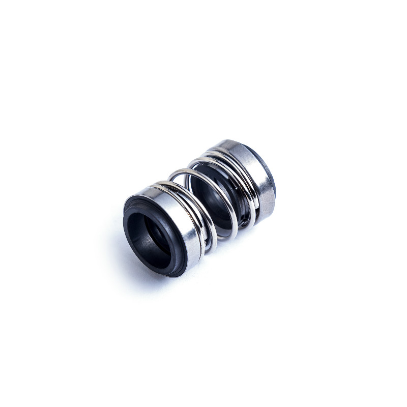
Users can choose different material for this double mechanical seal 208, matching for different liquid conditoncarbon, silicon, and tungsten carbide for this mechanical seal as seal face, if for high temerperature, we suggest to choose rubber seal viton for the rubber parts.
Lepu seal make this dual mechanical seal for many years, and offer professional suggestion when client need this grundfos seal, so we are your reliable specialist for grundfos mechanical seal.
Double mechanical seals are commonly used in the following circumstances:If the fluid and its vapors are hazardous to the operator or environment, and MUST be contained
Guangzhou Lepu machinery CO., LTD becomes one of the leading mechanical seal supplier in south of china, we focus in designing and manufacturing mechanical seal for many kinds of famous brand pumps, our mechanical seal cover many kinds of industry like food, petrol chemical, paper making, sea ship, and so on.

This website is using a security service to protect itself from online attacks. The action you just performed triggered the security solution. There are several actions that could trigger this block including submitting a certain word or phrase, a SQL command or malformed data.

But here I want to emphasize the importance of pumps, mechanical seals, and seal support systems. Without pumps, there is no process. Without the proper seal support systems, high temperatures in seal chambers may damage mechanical seals and lead to pump leakage.
While leakage can cause small problems or big ones, you always need to have the risk of sanctions in your mind, especially in high regulation states like California. And with Bay Area refinery budgets as lean as they are currently, it makes sense to choose the right systems from the start to avoid something costly going wrong in the future.
Several factors contribute to high temperatures in the seal chamber, which in turn leads to mechanical seal degradation. A mechanical seal and seal support system may have been perfectly matched to the initial process, working reliably for years. However, a change to a higher-temperature process can exceed the capability of the mechanical seal and capacity of the seal support system.
At higher temperatures, elastomeric components in the mechanical seal may begin to deteriorate. For example, beyond 300° Fahrenheit (150° C) ethylene propylene components eventually degrade and leak. Some hydrocarbons coke at higher temperatures and impede the free movement of mechanical seal components. And process fluids at high temperatures are prone to vaporize, or flash, across the seal faces, causing fugitive emissions.
With increased temperatures of process fluids, the seal support system may no longer be able to maintain the barrier or buffer fluid temperature or flow rate required to maintain the integrity of a dual seal arrangement. When mechanical seals and seal support systems can no longer ensure pump reliability it’s time to select seals, support systems, and components better suited for the job.
If a change to a higher process temperature is causing unanticipated leakage, consult with your preferred mechanical seal vendor. The materials alone can present an overwhelming number of options as seal technology and design continue to evolve. There are now more choices than ever, including:
⇒ Seal faces—carbon, stainless, ceramic, tungsten, and variants incorporating silicon, graphite, or nickel—engineered for resilience and compatibility with process fluids
The benefit of these choices is the ability to match mechanical seals to the specific needs of the process, maximizing seal performance and reliability.
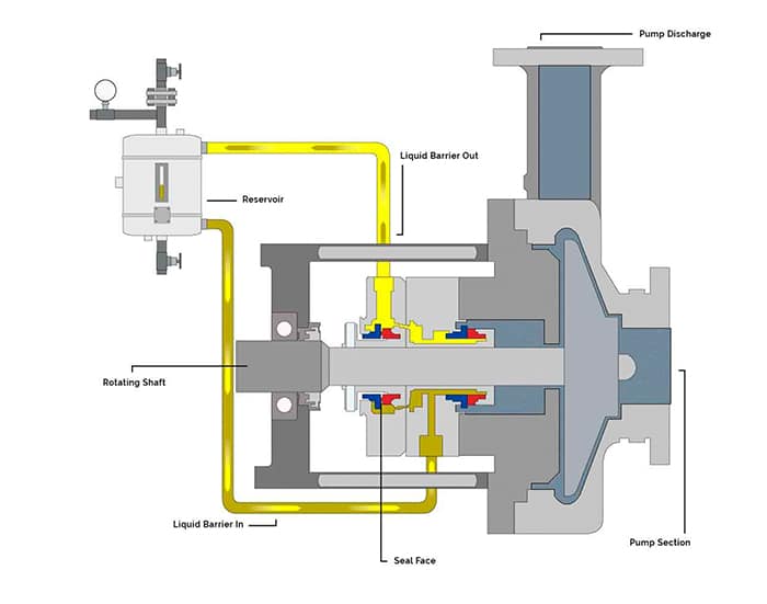
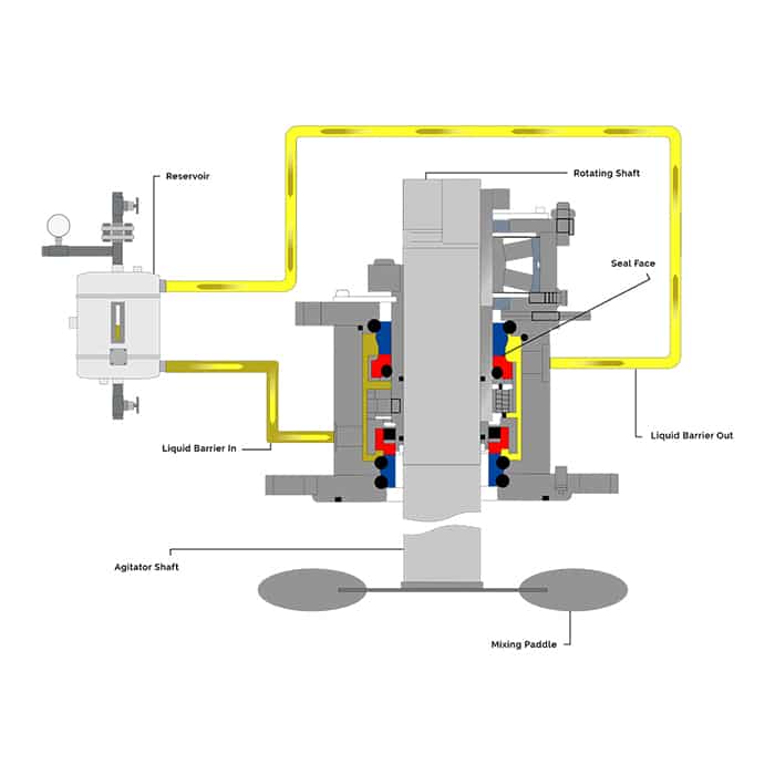
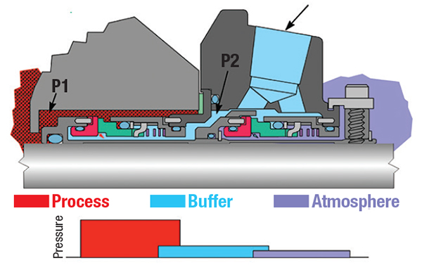
The mechanical seal requirements of high-temperature hydrocarbon processes are best met with dual/ between seal arrangements. A dual seal support system provides fluid between two seals, buffer fluid at a lower pressure than the process fluid, and barrier fluid at a higher pressure than process fluid.
In contrast to a single mechanical seal arrangement where seal degradation or failure results in fugitive emissions or outright leakage, the two seal arrangement provides a more reliable means of preventing high-temperature hydrocarbons from leaking. Here too, rotating equipment and reliability engineers have a number of dual seal design options to choose from, including:
Face-to-face configurations are used in space-constrained areas that cannot accommodate back-to-back or tandem arrangements. Seals share a common stationary component which, if compromised, leads to leakage. You can select from buffer or barrier fluid options.
Gradual or sudden changes in barrier or buffer fluid pressure provide evidence of problems with seals. An experienced mechanical seal vendor can help you navigate the options available to ensure mechanical seals and their components meet each of your specific needs.
Equally important to the reliable functioning of mechanical seals in high-temperature processes is the selection of seal support systems. The mechanical seal you choose will guide the seal support system plan that best meets your needs.
Seal support systems for dual seals are divided into two categories: buffer and barrier. While that seems to simplify the selection, there are a variety of options for each category. To give you an idea of what’s available, I’ve listed a few of the mechanical seal support system options below.
Circulates pressurized barrier fluid from a reservoir to the dual seals. Use plant nitrogen, bladder accumulator, or piston accumulator to supply seal pot pressure. Any leakage across the process side seal is barrier fluid that lubricates seal faces and migrates into process fluid.
Provides clean, dry pressurized barrier gas (typically nitrogen) to the dual seals from an external source. Any leakage past the atmospheric seal is pure nitrogen.
For each of these plans, there are options to fine-tune the seal support system and provide a greater level of reliability for mechanical seals operating in high-temperature environments. Among the many options you may want to include:
An experienced seal support vendor can save you time and money, helping you select and configure the seal support systems with the right components for each of your high-temperature hydrocarbon pumping needs.
Swagelok has been meeting the mechanical seal support system needs of Northern California refineries for more than 50 years. When you work with Swagelok, you have the benefit of a local vendor with facilities in Concord, Fremont, and Santa Clara. Being local translates into on-site support, field verification of your requirements, and rapid delivery of seal support system assemblies, components, and parts.
To find out more about howSwagelok Northern California can help you address the challenges of maintaining the proper environment for mechanical seals in high-temperature serviceContact our team today by calling 510-933-6200.
Paul holds a B.S. in Mechanical Engineering from North Dakota State University. Before joining Swagelok Northern California, he was the West Coast Regional Sales Manager for an organization involved in pneumatic and hydraulic applications where he supervised product distribution throughout the western United States, Canada, and Mexico. While in this role, he was able to help provide technical and application-specific expertise to customers and distribution to drive specifications.
A mechanical seal is simply a method of containing fluid within a vessel (typically pumps, mixers, etc.) where a rotating shaft passes through a stationary housing or occasionally, where the housing rotates around the shaft.
When sealing a centrifugal pump, the challenge is to allow a rotating shaft to enter the ‘wet’ area of the pump, without allowing large volumes of pressurized fluid to escape.
To address this challenge there needs to be a seal between the shaft and the pump housing that can contain the pressure of the process being pumped and withstand the friction caused by the shaft rotating.
Before examining how mechanical seals function it is important to understand other methods of forming this seal. One such method still widely used is Gland Packing.
The stationary part of the seal is fitted to the pump housing with a static seal –this may be sealed with an o-ring or gasket clamped between the stationary part and the pump housing.
The rotary portion of the seal is sealed onto the shaft usually with an O ring. This sealing point can also be regarded as static as this part of the seal rotates with the shaft.
One part of the seal, either to static or rotary portion, is always resiliently mounted and spring loaded to accommodate any small shaft deflections, shaft movement due to bearing tolerances and out-of-perpendicular alignment due to manufacturing tolerances.
The primary seal is essentially a spring loaded vertical bearing - consisting of two extremely flat faces, one fixed, one rotating, running against each other. The seal faces are pushed together using a combination of hydraulic force from the sealed fluid and spring force from the seal design. In this way a seal is formed to prevent process leaking between the rotating (shaft) and stationary areas of the pump.
If the seal faces rotated against each other without some form of lubrication they would wear and quickly fail due to face friction and heat generation. For this reason some form of lubrication is required between the rotary and stationary seal face; this is known as the fluid film
In most mechanical seals the faces are kept lubricated by maintaining a thin film of fluid between the seal faces. This film can either come from the process fluid being pumped or from an external source.
The need for a fluid film between the faces presents a design challenge – allowing sufficient lubricant to flow between the seal faces without the seal leaking an unacceptable amount of process fluid, or allowing contaminants in between the faces that could damage the seal itself.
This is achieved by maintaining a precise gap between the faces that is large enough to allow in a small amounts of clean lubricating liquid but small enough to prevent contaminants from entering the gap between the seal faces.
The gap between the faces on a typical seal is as little as 1 micron – 75 times narrower than a human hair. Because the gap is so tiny, particles that would otherwise damage the seal faces are unable to enter, and the amount of liquid that leaks through this space is so small that it appears as vapor – around ½ a teaspoon a day on a typical application.
This micro-gap is maintained using springs and hydraulic force to push the seal faces together, while the pressure of the liquid between the faces (the fluid film) acts to push them apart.
Without the pressure pushing them apart the two seal faces would be in full contact, this is known as dry running and would lead to rapid seal failure.
Without the process pressure (and the force of the springs) pushing the faces together the seal faces would separate too far, and allow fluid to leak out.
Mechanical seal engineering focuses on increasing the longevity of the primary seal faces by ensuring a high quality of lubricating fluid, and by selecting appropriate seal face materials for the process being pumped.
When we talk about leakage we are referring to visible leakage of the seal. This is because as detailed above, a very thin fluid film holds the two seal faces apart from each other. By maintaining a micro-gap a leak path is created making it impossible for a mechanical seal to be totally leak free. What we can say, however, is that unlike gland packing, the amount of leakage on a mechanical seal should be so low as to be visually undetectable.

DuraClear Crystal 7 Seal Lubricant is a premium barrier fluid for use on equipment handling high purity, high value or highly reactive product fluids such as strong acids and bases. It has been specifically formulated for the lubrication needs of dual mechanical seals. When chemical compatibility is critical, this environmentally friendly and nonreactive barrier fluid extends the life of dual mechanical seals for increased process yield and throughput.
CTFE fluids may react violently with K, Na, amine, hydrazine, liquid fluorine, liquid chlorine trifluoride, Aluminum, Aluminum Chloride (AlCl3) and Aluminum Oxide (Al2O3)
We have a pump which pumps 23% NAOH (sodium hydroxide solution) It is protected by a double seal and barrier fluid system (seal pot) system. The pump has the double seal to protect for leakage to the environment and acts as a lubricant to the seal. The mechanical seal is changed out on LIFE every 24 months to avoid seal failures. In general, this works very well for us and we seldom have unscheduled failures of these seals. The seal pot fluid used is filtered water which is piped in to the pot and we have have flow and level change detection inside the pot. This provides information and alarms to our control system to detect abnormal usage of the filtered water which would indicate loss of barrier fluid into the process i.e. a seal leak.
Recently, one of our technicians noted a small drip from the drain on the pot. He noted that the residue form the drip on the ground was white in colour. I took a sample of the seal pot water and had it analysed. pH was 9.4. for reference, i pulled a filtered water sample further back on the filtered water header and it was pH 6.8. I shut down the pump and flushed out the seal pot and resampled for pH. It came back at a pH of 8. I put the pump back on line and ran it for 24 hrs and resampled. The pH was 8.4 (slightly up on the previous result) Everything seems normal with the filtered water pressure to the pot so I am wondering how we are getting contamination back into the seal pot water. Anyone out there have any view or experience of contamination getting back into a barrier fluid system? Appreciate any views on this
![]()
www.plantservices.com is using a security service for protection against online attacks. An action has triggered the service and blocked your request.
Please try again in a few minutes. If the issue persist, please contact the site owner for further assistance. Reference ID IP Address Date and Time 294f57d3f1ba3bc2bb8db2ce5bf45ccf 63.210.148.230 03/03/2023 12:54 PM UTC

www.machinedesign.com is using a security service for protection against online attacks. An action has triggered the service and blocked your request.
Please try again in a few minutes. If the issue persist, please contact the site owner for further assistance. Reference ID IP Address Date and Time 20ed59e0f57c4a558f474ac5bb94baa0 63.210.148.230 03/03/2023 12:54 PM UTC

Pumping of low-temperature and cryogenic fluids requires specific and unique engineering technologies for the shaft sealing system. When correctly applied, these technologies provide the containment and reliability to meet pumping equipment operators’ requirements.
Due to their extreme sub-zero temperatures, low-temperature hydrocarbons and liquefied atmospheric gases pose significant challenges to pumping, and particularly to the specification of their shaft sealing systems. To provide long-term reliability while ensuring that these pumped fluids are safely contained, the designs of the shaft seals used in cold-fluids pumps are often highly specialized.
For example, low temperatures have significant implications for the choice of materials used in the seal construction. Metals become increasingly brittle as the temperature is reduced; therefore, thermal constriction and expansion must be factored. The volatility and flammability of low-temperature hydrocarbons pose special challenges for the design of pump shaft seals, as well as for the release of hazardous emissions to the atmosphere. Liquefied oxygen, with temperatures much colder than these hydrocarbons, is a strong oxidizer and can cause certain materials to spontaneously combust.
Low-temperature hydrocarbons are typically pumped at sub-cryogenic temperatures, between –20°C and –140°C (–5°F to –220°F), although lower temperatures are occasionally encountered. They have high vapor pressures at ambient temperatures and are pumped at low temperatures to reduce the pumping pressures. These hydrocarbon fluids include ethylene, LNG, LPG, methane, butane and propylene.
Low-temperature hydrocarbons are commonly pumped with API 610 (VS6) vertical multistage double-casing pumps that feature a warming chamber, known as a cofferdam (Fig. 1), which thermally isolates the shaft seal from the cold pumped fluid. Cofferdams enable a greater range of shaft sealing solutions to be used on these pumps, utilizing traditional sealing technology.
A cofferdam is a chamber between the pump discharge and the mechanical seal that is connected to the pump suction, or the vessel from which the pump is drawing suction. Ambient heat surrounding the pump, together with energy from the shaft and bearings, causes the liquid in this chamber to vaporize into a gas, which forms an insulating barrier between the seal and the process fluid. Cofferdams can be incorporated only into vertical pump designs.
Although vertical arrangements are common, various horizontal pumps can also be used. In these types of pumps, the shaft seal is in direct contact with the cold-pumped fluid; therefore, selection of the seal materials for low-temperature operation becomes more critical.
Similar to pumping equipment for low-temperature hydrocarbons, pumps used for liquefied atmospheric gases have a combination of vertical multistage pumps, together with horizontal single-stage pumps. These systems generally do not follow API pump design standards.
For pump designs where the mechanical seal is immersed in the pumped fluid, the vapor pressure margin in the seal chamber becomes critical. Where the vapor pressure margin is low, the heat energy from the mechanical seal faces can vaporize the fluid around the seal and in the seal interface, resulting in dry running of the seal. In this situation, a dual-pressurized seal is required. A dual-pressurized seal provides a stable barrier fluid to lubricate the seal faces, thereby negating the effect of vaporization of the pumped liquid at the seal faces.
API Plan 53B and 53C barrier systems are commonly selected for dual-pressurized seals to provide a source of warm, clean and stable barrier fluid to the mechanical seal. When an API Plan 53C system is selected, extra care should be taken to ensure that the pressure-amplifying piston and rod seals are insulated from exposure to cold temperatures.
The availability of suitable barrier fluids becomes limited at low temperatures, as the viscosity of many fluids becomes too high at the seal chamber operating temperatures. Mono- and di-ethylene glycol mixtures with water can be used down to temperatures of –29°C (–20°F). Alcohols, such as propanol (propyl alcohol), are suitable for even colder temperatures reaching –70°C (–95°F). Synthetic oils can also be used; however, careful consideration to their pour point is required, and a heating system may be needed to warm the barrier fluid to maintain a suitable viscosity.
When sufficient vapor pressure margin exists within the seal chamber, a dual-unpressurized seal can be selected. Typically, these designs feature a dry-sliding containment seal fitted with API Plan 76, or a combination Plan 72 and 76. These seal arrangements have the advantage of removing the low-temperature limitation of barrier fluid selection.
Pump designs utilizing a cofferdam require a dual-pressurized mechanical seal, as the seal chamber contains no liquid to lubricate the mechanical seal faces.
Icing, due to condensation of atmospheric humidity, can create a problem for sealing systems handling cold hydrocarbons. Since condensing water expands as it freezes, it can interfere with the operation of the mechanical seal if it reaches the seal’s operating mechanism. Extra protection should be applied to equipment exposed to atmospheric elements, such as rain. An API Plan 62 using a dry nitrogen quench can displace atmospheric humidity, thereby protecting the mechanical seal from these effects.
In applications handling liquefied atmospheric gases, pump seal reliability takes precedence when selecting a shaft sealing system. Unlike hydrocarbons, emissions of gases to the environment by liquefied atmospheric gases pose relatively minor hazards and, therefore, are not as critical a factor as seal reliability.
Two commonly employed shaft sealing technologies are used in pumps handling liquefied atmospheric gases: single mechanical seals and segmented bushings.
Single mechanical seals.The most common solution for pumps used in air liquefaction plants and mobile-transportation unloading pumps is the single mechanical seal. The major difference between the two is that the mobile unloading pumps tend to be smaller and often use non-cartridge seals. Cartridge seals are commonly found in larger machinery at air liquefaction plants. Single mechanical seals fall into two sub-categories: contacting wet seals and vaporizing liquid gas seals.
Contacting wet seals utilize a metal bellows to provide elastomer free-axial flexibility. Seal face materials typically include filled tetrafluoroethylene running against a tungsten carbide or hard-coated, stainless steel mating ring.
Vaporizing liquid gas seals (Fig. 2 and Fig. 3), similar in construction to contacting wet seals, feature engineered seal-face topography that allows the controlled vaporization of the pumped atmospheric gas to produce a highly reliable seal that exhibits controlled, low-level leakage rates.
Segmented bushings.A segmented bushings sealing configuration is often found in vertical multi-stage pumps at air liquefaction plants. The design provides a controlled leakage by breaking down the sealed pressure over a series of tightly controlled bushing clearances. Leakage rates are higher than those of mechanical seals; however, these leakage rates are often considered acceptable by this industry.
As mentioned, low temperatures have significant implications for the choice of materials used in the seal construction. This is especially true for elastomers applied in seals for pumps handling low-temperature hydrocarbons. Depending on the material grade used, elastomers have a variety of minimum temperature limits, but none can survive dynamic operation at true cryogenic temperatures.
Engineered polymer seals are an option at temperatures below the limits of elastomers; however, many of these designs will not function with pressure reversals applied to the sealing ring, which may be required in the mechanical seal design when support system failures occur.
Elastomers can survive at significantly lower temperatures below their operational limits when the seals are not in operation (i.e., static); however, they must be warmed up prior to operation. Commissioning of shaft seals containing elastomers must be completed carefully to ensure that equipment is at the correct temperatures before startup. Blowdown—the rapid depressurization of a vessel/pipeline—is one situation that can create excessively low temperatures for mechanical seal elastomers.
Thermal expansion and contraction are also considerations. The cavities in which elastomers or engineered polymer seals are installed will change with decreasing temperatures, as well as the dimensions of sealing elements installed in these cavities. Additionally, clearances between dissimilar materials, such as bushings, will require review. Mechanical seal manufacturers take these factors into consideration during the design of the mechanical seal for these cold services.
Since pumping equipment is often used interchangeably between different atmospheric gases, sealing of liquefied atmospheric gases presents some unique challenges to the selection of materials.
Liquefied oxygen is a strong oxidizer and can cause certain materials to spontaneously combust. Additionally, any organic contaminates on the seal can lead to spontaneous combustion, including metal cutting fluids, fibers from cleaning rags, and even oils from human fingerprints. To meet oxygen service requirements on seals, stringent cleaning specifications must be employed to ensure that the seal is free of any contaminates that may create a fire hazard while in service. Additionally, the materials of construction must include materials that are compatible for use in oxygen service.
Aluminum alloys should be avoided, as they can become hazardous when their protective oxide film is stripped from the material, such as when abrasion occurs. Lubricants used in the assembly and operation of the mechanical seal must be free of hydrocarbons and compatible for use in oxygen service. Packaging of the seal should also be suitable to preserve the cleanliness of the seal prior to installation into the pumping equipment, which must be performed in a suitably clean environment.
Of the many pump mechanical seal applications in use throughout various industries, those that deal with low-temperature and cryogenic processes rank among the more challenging.
It is critical to keep these seals, which handle low-temperature hydrocarbons and liquefied atmospheric gases, in optimal operating condition to ensure that the pumped fluids are safely contained, while providing long-term reliability. HP
Mark Savage is a Product Group Manager at John Crane, responsible for the application, design and development of metal bellows seals for pumps, compressors and rotating machinery. He has worked in the sealing industry for 25 yr and has been involved with the development of best practices for shaft seals and their support systems. Mr. Savage holds a BE degree in mechanical engineering from the University of Sydney, Australia. He is a member of the Fluid Sealing Association and Vice Chair of the Association’s Mechanical Seal Division, Chair of the Mechanical Seal Technical Committee and Vice Chair of the Government Relations Committee. He is also a member of NACE International and the Society of Tribologists and Lubrication Engineers (STLE). Mr. Savage has authored several publications on mechanical seals and support systems and their application to minimize environmental impact.

From the operational point of view of centrifugal pumps, it becomes essential to correctly align the pump and the drive to ensure the mechanical seal functions properly. Attention shall be given to is nozzle loads. During the design as well as during the actual installation, the consideration of the nozzle loads is important. Higher nozzle loads beyond allowable values could lead to deformed casings and may be detrimental to mechanical seals due to rubbing of the shaft at the clearances. The sizing of the shaft in case of end suction pumps (and also the overhang) has to be controlled, which could result in excessive deflection at the mechanical seal faces.
When it comes to reliability of sealing the process liquid, a dual seal arrangement is the preferred choice. There are three arrangements defined in API 682: arrangement 1, 2, and 3. The arrangement 1 is the single seal arrangement. The arrangement 2 is the dual seal arrangement with unpressurized buffer liquid at the outboard seal. Finally, arrangement 3 is the dual seal arrangement with the pressurized barrier liquid at the outboard seals. With the barrier liquid being pressurized in arrangement 3, there is no leakage of process liquid to the atmosphere, and hence it is the most reliable option when it comes to applicability of stringent environmental norms from the point of view of the end user.
However, in order to ensure proper functioning and reliability of dual seals, the operational environment of the pump, piping, seal support system, and monitoring systems play a vital role. There are typically four API piping plans for seal support systems: API Plan 53 A, B, and C, and Plan 54.
All three variations of Plan 53 are similar from the point of view that they circulate the barrier fluid using the pumping screw inside the mechanical seal, but the methods of pressurizing the barrier fluids are different. Plan 53A uses direct pressurized nitrogen to pressurize ¬fluid in the reservoir. This plan is popularly used in most of the cases due to less complexity and also availability of nitrogen pressurizing source at site. However, to ensure reliability, one has to be careful about the absorption of nitrogen gas into the barrier ¬fluid. The amount of gas being absorbed is proportional to the pressure of the barrier system. The barrier ¬fluid with absorbed gas then reaches the seal faces due to circulation and at the ¬fluid film, due to depressurization, the gas may come out and hamper the seal performance. This is a reliability concern, and hence most of the seals with Plan 53A are limited to 10 bar (gauge) pressure. Plan 53B uses a bladder accumulator as a means of pressurization of barrier fluid. This overcomes the limitation of Plan 53A and the absorption of nitrogen into the barrier liquid, which limits the system pressure, which can be used in high pressure applications. The advantage of the Plan 53B is that it can be used in remote locations where the external source of pressurization is not available. The pressure of barrier liquid is maintained due to the expansion of the bladder inside the accumulator, which also enables the supply of make-up barrier liquid to compensate for a small amount of leakage of barrier -fluid. However, the monitoring of the liquid level in the reservoir is not possible, and as such, the sizing of accumulator considering the seal leakage and maintenance interval is critical. As the bladder expands to compensate for seal leakage, it needs to be refilled with barrier liquid. The usual cycle of refill is 25 to 28 days. Considering this as a basis, the size of the accumulator and the pre-charge pressure of nitrogen is estimated.
Plan 53C uses a piston as a means of pressurization of barrier ¬fluid inside the accumulator. The advantage of this design is that it uses the process fluid pressure from the seal chamber directly on the bottom side of the piston, whereas top side is exposed to the barrier liquid. The pressurization is achieved by the difference in the areas. The area exposed to process liquid is larger and is designed with ratios ranging from 1:1.1 to 1:1.25. As the seal chamber pressure is being used as a reference, the system itself takes care of process pressure fluctuations. However, as the piston is in direct contact with the process fluid, the material selection becomes essential. Also, the properties and quality of process ¬ fluid shall be carefully evaluated, it should not hinder the movement of the piston within the accumulator. Another important factor is the dynamic sealing of the process fluid from the barrier fluid. The failure of the piston seal will result in the equilibrium of pressures on both sides of piston, and because of the piston movement, friction and drag come into play. Thus, the plan is not so reliable for low pressure applications and recommended to be used in the applications with pressures greater than 7 bar (gauge).
Although a mechanical seal is a critical piece of equipment, it shall not be treated in isolation and due consideration should be given to the operating environment of the pump, seal support system, and most importantly, the perfect selection for the given application.
Abhijeet Keer is a design engineer who has been working in the fi eld with centrifugal pumps for over seven years. With strengths in mechanical construction and materials, he has gained valuable knowledge working in design with major players in pump industry, such as KSB Limited and Kirloskar Brothers Limited. He completed his Bachelor’s Degree in Mechanical Engineering from University of Mumbai, India. His professional experience covers new product design and developments, material selection and application engineering, and complete mechanical constructions.

Mechanical sealsare used in pump systems to help join the systems together and prevent leakage of the pumped product, contain pressure, and exclude contamination. A typical system for a simple mechanical seal is comprised of the seal, the stuffing box throat bushing, a liquid flush system, an auxiliary seal and flush, as well as barrier fluid, if necessary. Most modern pump systems are moving more towards mechanical seals as opposed to traditional pump packing and while there are many advantages to using the mechanical method, it does come with its potential failures.
Mechanical seal failure is a common issue, afflicting operators and engineers from many different industries. As with most failures, the most common reason
Before installation, the most critical error that most people make is selecting the incorrect seal for the application. Seals fall into many different
categories, so you need to consider your normal operating conditions, machine set-up, and non-process activities such as cleaning and flushing, before
Once you have the correct seal for the application, it’s important to remember that mechanical seals need to operate in a properly controlled environment
cooling systems in place. Mechanical seal faces are incredibly flat making them extremely sensitive to contamination. Even the smallest amount of dirt,
An improperly installed and misaligned seal causes damage to the O-rings and can result in pump vibration, which will cause extensive damage to the equipment
and seals themselves. Vibration can also be the result of pump imbalance or from operating the pump outside of its BEP (Best Efficiency Point). Another
error that is commonly made is using a hammer to pound couplings onto the shaft. Hammers and fragile seal faces do not go well together and continuing
Once the seal has been installed correctly, there are still important points to remember during operation to avoid causing any unnecessary damage. Incorrectly starting the pump can cause the motor to trip and the shaft to twist. This orbital movement will cause the internal parts to contact, resulting in seal failure andbearingwear. Allowing the pump to run dry can also be detrimental to mechanical seals, causing thermal shock and nearly instant shattering. A critical element to using mechanical seals is a coordinating flush plan. Without a flush plan, contaminants build up, causing extreme heat and seal erosion.
To avoid the potential pitfalls mentioned above, look to your trusted, local seal supplier for assistance with selecting the correct seal and for guidance on the best operational and installation practices. AtBearing Centre, we pride ourselves on our superior service and industry expertise. Give us acall today!
Mechanical seals touch nearly every aspect of industrialized society. Wherever a rotating shaft moves fluid, mechanical seals play a key role in sealing process fluids in, keeping contaminants out, or both.
A few basic components and principles in mechanical seal design contribute to a working seal at the interface of the rotating shaft and stationary pump/mixer/seal-chamber housing. Mechanical seals are usually end-face seals or rotating-face seals, but in some designs they can be circumferential or even a hybrid of lip-type seals. In either case, the following components are common to all mechanical seals:
Stationary primary sealing element:fixed to the stationary housing of the pump, mixer or other equipment through which the rotating shaft passes and seals against the rotating primary sealing element
The more common end- or rotating-face mechanical seal designs feature mating faces as the primary sealing elements. Rings of ceramic, carbide, carbon or composites of these materials are lapped flat in the range of less than 1 micron on an axial end face. These lapped faces run against each other, one rotating with the shaft and the other stationary with the equipment housing.
The sealed fluid migrates between the flat faces and forms a stable fluid film at this interface. During shaft rotation, the face materials heat up, wear and degrade quickly without a lubricating fluid film between them. The sealed fluid creates this thin lubricating film.
In a lip-seal-type mechanical seal, a thin film of sealed fluid also lubricates the sealing interface. Rather than two flat rings, the sealing interface is a polymer material deflected against a hard material. This material could be a hardened, coated or plated metal, ceramic, or carbide face or sleeve. One of these elements rotates with the shaft while the other is stationary with the equipment housing.
Leakage is a function of the mathematical cube of the film thickness, so to minimize leakage, the gap at the sealing interface must be kept at a functional minimum. Closing forces are used to optimize this design parameter throughout the operating range of the mechanical seal.
The initial closing force ensures that the seal will function properly from startup. In end- or rotating-face mechanical seal designs, the initial closing force is provided by a spring component, which can be a single coil spring, multiple coil springs, a deflected bellows unit (elastomer or metal), or formed or flat springs. Initial biasing forces also can be created by magnets, compressed elastomers or any other means of applying a closing force between sealing elements. In a lip-type mechanical seal, the initial closing force is typically from the deflected polymer of the lip-type seal or a garter spring for less resilient materials.
The sealing elements must be secured to the rotating shaft and stationary housing of the equipment being sealed. O-rings, gaskets and other elastomer seals stop leakage at these interfaces.
A static secondary seal stops leakage between components that do not move relative to each other. One example is the interface between a sleeve and a shaft, where both rotate but do not move relative to each other. A dynamic secondary seal, on the other hand, stops leakage between components that move relative to each other. An example is a spring-mounted seal face, where the face is free to move as the spring deflection allows, and the secondary seal will stop leakage between the seal face and the component to which it is resiliently mounted.
A lip-type mechanical seal may only require static secondary seals because the deflection of the lip-type seal accommodates equipment operating motion. All effective end- or rotary-face mechanical seals require at least one dynamic secondary seal. This is because the mating faces of the sealing interface are rigid materials that cannot comply with any equipment shaft/housing misalignments, thermal growth and shaft end-play. The dynamic secondary seal will accommodate the relative motion between at least one of the seal faces and the component to which it is mounted.
Mechanical seals are used with many process fluids. Each fluid has different lubrication qualities, but a thin, lubricating film at the sealing interface is always needed. A film that is too thick will increase leakage and may allow particulate between the faces, which will increase wear from abrasion. A film that is too thin will generate heat and cause materials to degrade. Keeping the sealing interface cool and clean will promote longer seal life.
Seal design can influence film thickness by balancing the closing forces on the sealing interface in such a way that the sealing interface does not become overloaded as process pressures increase. A closing force that is too high will lead to a fluid film at the sealing interface that is too thin, generating detrimental heat.
Another way to influence film thickness is to design surface features at the sealing interface that promote hydrodynamic lift between the rotary and stationary sealing elements. This can help create a purposeful separation at the sealing interface that results in a thicker fluid film that provides cooling and decreases face wear.
Primary seal material selection can influence seal life as well. Chemical or process compatibility is just one consideration. Harder materials are more resistant to abrasive processes, but if both sealing elements are hard materials, the wear characteristics may be less desirable in a nonabrasive application.
Using one sealing element made of a softer material and/or one that contains lubricating components such as graphite decreases friction for starting and incidental contact. The use of composite hard faces will also reduce friction by providing microscopic reservoirs of system fluid at the interface.
Thermal conductivity of materials will dissipate heat away from the sealing interface, promoting seal life. Material toughness also can play a dominant role in mechanical seal life. The inherent material surface texture may also play a role in promoting desirable film thickness.
Note that many seal failures result from failed secondary seals that have exceeded chemical compatibility, pressure or temperature limits. Metal parts must be compatible to avoid corrosion, and springs and other hardware must hold up in service.
Process and seal environmental controls greatly contribute to a cool, clean lubricating film at the sealing interface. If the process fluid is a slurry mixture, process pressure will drive the particulate-laden fluid into the sealing interface, resulting in abrasion and accelerated wear.
Environmental controls, such as a restriction bushing and clean flush, can isolate the mechanical seal from the harsh process so the seal is mostly sealing the cleaner, cooler flush fluid. In other cases, the pump product may crystallize, abrading the sealing interface and causing premature wear. Product crystallization can be prevented by using temperature controls, quenching the atmospheric side of the sealing interface, or using a double seal with a buffer or barrier fluid.
There are many process considerations other than abrasion that might prevent a cool, clean lubricating film at the sealing interface. If the sealing fluid has a low vapor point, for example, flashing can result. Flashing occurs when the sealed fluid changes from liquid to gas at the sealing interface, expanding quickly and forcing the sealing elements apart until the pressure and temperature are relieved, only to have the sealing elements collapse back into contact. Mechanical damage to the sealing contact surfaces quickly results in seal failure. No lubricating film is established. Operators must incorporate process controls and ensure proper mechanical seal selection to prevent such upsets. There are many other process conditions that require special attention such as fluids that harden, are toxic, must be kept anaerobic, are part of food or water supply, or present another specific constraint.
Seal environmental controls are often overlooked, resulting in surprisingly short seal life. Many seal failures of this type happen in cool water applications. Cool water is an effective sealing fluid for creating a stable lubricating film at the sealing interface, but failure to apply proper seal environmental controls can lead to seal failure.
Many cool water applications fail prematurely because they are vertical, with the seal installed at a high point in the system where air is trapped. Without properly venting the air out of the seal chamber area, the mechanical seal seals air, not cool water. This is a dry-running condition that generates heat and quickly degrades the materials at the sealing interface.
A common environmental control used in vertical applications is a recirculation line from the seal chamber to pump suction, but in some cases the seals run dry for too long before the fluid replaces the air in the seal chamber.
Poor equipment conditions—caused by bad bearings, cavitation, excessive impeller loads and misaligned shafts—result in excessive motion, vibration and mechanical shock to the mechanical seal. These conditions cause greater stresses, more heat and more opportunity for abrasives to enter the sealing interface.
Mechanical seals are designed to handle a range of motions and conditions, but they are just one machinery component in a larger system. Understanding the basics of mechanical seals and how they may be adapted for different application requirements is critical for choosing the best seal for the job and ensuring optimal system reliability.
We invite your suggestions for article topics as well as questions on sealing issues so we can better respond to the needs of the industry. Please direct your suggestions and questions to sealingsensequestions@fluidsealing.com.


 8613371530291