
barrier fluid in mechanical seal factory

This website is using a security service to protect itself from online attacks. The action you just performed triggered the security solution. There are several actions that could trigger this block including submitting a certain word or phrase, a SQL command or malformed data.

As operators of pumping equipment become more focused on the safety, reliability and environmental impact resulting from shaft seal leakage, dual mechanical seals have become more prevalent in the industry. A dual mechanical seal offers a second (outer) seal to contain the pumped fluid by creating a cavity or chamber between the inner and outer seal that can be filled with a fluid. When this fluid is unpressurized, it forms a buffer between the pumped fluid and atmosphere and is commonly referred to as a buffer fluid. When pressurized, it forms a barrier between the pumped fluid and atmosphere and is known as a barrier fluid.
Although mechanical seal designs are available in configurations that use either a liquid or a gas as a barrier fluid, the following discussion focuses on liquid buffer and barrier fluids only. In addition to separating the pumped fluid from the atmosphere, liquid buffer and barrier fluids lubricate the mechanical seal and transport frictional heat and absorbed heat from the mechanical seal to a heat exchanger. This controls the fluid’s temperature and lubricating properties.
Buffer/barrier fluid can be stored, monitored and delivered using many methods. Each is identified by a piping plan number that describes the minimum requirements of each system. The most commonly referenced piping plan originates from the American Petroleum Institute’s standard API 682.
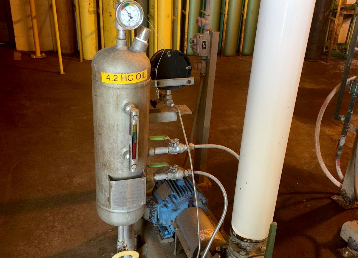
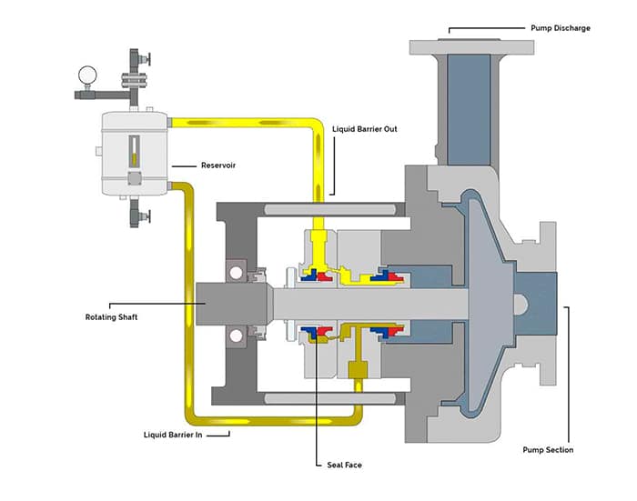
A Plan 52 system (see Figure 1) provides a reservoir that stores the buffer fluid. Supply and return lines are connected to the mechanical seal and circulation of the buffer fluid is achieved by an internal circulating device (pumping ring) within the mechanical seal. The vapor space above the buffer fluid in the reservoir is vented to atmospheric pressure typically via a flare or vapor recovery system. The reservoir can be instrumented to measure the liquid level and pressure in the reservoir. Ports are fitted to the reservoir to facilitate maintenance activities—such as inspection and cleaning or refilling and draining the buffer fluid. Cooling is accomplished using an internal heat exchanger.
Pressurized dual seal systems contain the same essential components as an unpressurized system. However, they also contain a way to pressurize the barrier fluid. The following plans may be used for pressurized dual seal systems:
Plan 53A—A pressurized gas blanket in the reservoir pressurizes the fluid. Nitrogen is normally used and the pressure is controlled via a pressure regulator (see Figure 2). The barrier fluid is in direct contact with the pressurized gas.
Plan 53B—Pressure is generated as a nitrogen-filled bladder is compressed by the addition of barrier fluid into the bladder accumulator. The bladder prevents direct contact of the pressurized gas with the barrier fluid.
Plan 53C—A pressure amplifying piston uses pressure from within the pump (typically the seal chamber) to amplify the barrier pressure by the ratio of the area on each side of the piston. The barrier fluid is not exposed to any pressurized gas.
Plan 54—An external system is used to pressurize and circulate the barrier fluid. A Plan 54 system can be broadly classified into two groups: closed- and open-loop systems. In closed-loop systems, the barrier fluid is stored in a large reservoir and pumps pressurize and circulate the fluid. In open-loop systems, a compatible process stream is used as the barrier fluid and is circulated through the mechanical seal and returned to another point downstream in the process.
Several critical properties of a buffer or barrier fluid must be considered when making a selection. An ideal buffer or barrier fluid will have the following properties:
Water offers several benefits as a buffer/barrier fluid. Its thermal conductivity is about three times greater than oils and its specific heat is about twice that of oils, so it is good at transporting heat away from a mechanical seal. Water is inexpensive, easy to handle and store, has few seal material compatibility issues and is nonflammable. It is also compatible with many aqueous pumped solutions. Its viscosity is generally around 1 centistoke at moderate temperatures which offers low resistance to flow in the barrier system.
However, the viscosity becomes low at elevated temperatures limiting its effectiveness as a lubricant for the mechanical seal faces. Water is also susceptible to freezing during the winter months. This results in a narrow window of service and environment temperatures in which water can be used.
Generally, oils can be used in a much wider range of service temperatures. Compared to water, oils offer greater fluid stability at elevated temperatures and are not susceptible to freezing. They also provide excellent lubrication of the mechanical seal faces and, therefore, have the potential to offer longer seal life. Few compatibility issues with mechanical seal materials exist.
Oils are available in a wide range of types, compositions and viscosities. Traditional oils used in the industry include turbine oils and automatic transmission fluids. However, performance as buffer and barrier fluids has not been as successful as other oils, primarily because of the complex mixture of additives in these fluids.
Good performance can be achieved from oils with viscosity below that of ISO Grade 32 oils. High viscosities can result in damage to the mechanical seal faces, particularly when carbon is used as a face material. Paraffinic-based oils also generally perform better than naphthenic oils while synthetic oils offer even better performance. Synthetic lubricants specifically developed for use as a buffer/barrier fluid are now available in the marketplace and offer excellent performance. However, this performance is achieved at the sacrifice of cost.
We invite your suggestions for article topics as well as questions on sealing issues so we can better respond to the needs of the industry. Please direct your suggestions and questions to sealingsensequestions@fluidsealing.com.
Water is readily available. It is environmentally acceptable and has no health and safety restrictions. It also has a high specific gravity and specific heat which aids in heat transfer. For all of its favorable properties however, water has severe limitations as a barrier fluid. Pure water is a poor lubricant. At ambient conditions, water has viscosity that is suitable for lubricating seals with carbon vs hard face combinations. The viscosity decreases rapidly as the temperature increases. By 71°C (160°F), the viscosity is low enough that the fluid film in a standard seal fails to support the face often resulting in higher wear rates. The low viscosity of water can also create problems for Plan 54 systems.
This article is an excerpt from a paper, "Barrier and buffer fluid selection and considerations for mechanical seals" by Michael Huebner of Flowserve Corporation at the 2016 Turbomachinery & Pump Symposium.
Many Plan 54 systems are designed as an open system and use a positive displacement pump to create pressure and circulate the barrier fluid through the system. Many of these positive displacement pumps are designed with rubbing or sliding pump components that are designed to operate on a lubricating fluid. Operating these pumps on water can greatly reduce the reliability of the Plan 54.
Water at low temperatures can introduce different concerns. At 0°C (32°F), water freezes. This can have a severe impact on the condition of the seals and the auxiliary components. When a pump is in operation, the water barrier fluid may be heated by the process or the seal generated heat. In standby service though, the barrier fluid may reach ambient temperature conditions. Water is relatively non-corrosive but it will rust wrought and cast carbon steels. Normal seal piping plans will use stainless for most components but may use carbon steel for the reservoir to reduce cost.
Water barrier or buffer fluid systems must be designed with non-rusting materials. Not all water supply systems have clean, pure water. Contamination in the systems (e.g. rust or dirt) as well as water treatment chemicals (e.g. descalers, rust inhibitors, biocides, etc.) may affect chemical compatibility of the seal components or the lubricating properties between the seal faces. Users must ensure that the water supply is clean and suitable as barrier fluid.
One of the primary reasons why water is selected as a barrier fluid is for compatibility with the process fluids. In normal operation, small amounts of barrier fluid will leak into the process. In some processes, pure water introduced into the system would not be considered as a contaminant in the process. Water, specifically condensate, is the most common barrier fluid in the food processing, pharmaceutical, and biotech industries.
Many of the shortcomings of water can be addressed by mixing the water barrier fluid with other chemicals. The most common mixtures are water with either Ethylene Glycol (EG) or Propylene Glycol (PG). The addition of a glycol to the water depresses the freezing point and elevates the boiling point. It also increases the viscosity of the mixture which can provide better lubrication to the seal faces. It does this while still maintaining the high specific gravity and specific heat required for effective heat transfer. The improved properties made this buffer fluid an industry standard in refineries in light hydrocarbons services for many years.
Ethylene glycol is commonly used as a heat transfer fluid in industrial applications and automobile cooling systems. Automotive anti-freeze is most commonly a mixture of EG and other chemical additives. These other additives provide useful properties to automotive applications including preventing rust and corrosion, descaling metal surfaces, and stopping leaks in the cooling system. While these additives enhance the performance in automotive applications, they can cause high wear on the seal faces and reduce the reliability of the seal. For this reason, automotive anti-freeze should not be used in barrier or buffer fluid systems. Only pure EG or PG should be used. While ethylene glycol improves the properties of the barrier fluid, it has the drawback of being mildly toxic. Casual exposure to the skin is not considered a significant hazard but it must not be ingested and leakage into the environment may be regulated. For these reasons, many users have switched to propylene glycol/water mixtures. The properties of PG/water and EG/water are comparable and they will provide similar performance in most applications.
Propylene glycol is considered non-toxic and is safe for human exposure. Food grade PG is available and can be used in many food handling processes. Propylene glycol should be the first choice for glycol/water barrier and buffer fluids in most applications.

Any time you use two seals in an application you will need a fluid between them. If the fluid between the seals is higher than stuffing box pressure we call it barrier fluid. If it is lower than stuffing box pressure we call it buffer fluid The liquid can be circulated either by forced circulation, a pumping ring or convection. The method that you will use will be dictated by the pressure, pump speed and shaft size. All seal manufacturers have charts available to give you the correct guidelines.
If you elect to use a forced circulation system be sure to introduce the fluid into the bottom connection and out the top connection. This arrangement will insure that the space between the seals is vented and proper cooling will take place.
Forced circulation is the recommended method with all vertical shaft applications, although it is possible to offset the centering of the seal gland and get a small amount of pumping action as the liquid circulating in the seal changes its velocity at the convection tank connections. Check with your local distributor for an explanation of this principle.
Many of the latest seal designs utilize a built in pumping ring to enhance convection. This pumping arrangement is very necessary when ever oil is used as the barrier fluid. The following illustration shows a typical convection system that can be used with two balanced seals.
Water is one of the best barrier or buffer fluids because of its high specific heat and good conductivity. Petroleum oil is probably one of the worse because of its low specific heat and poor conductivity. Keep this in mind when you select a barrier or buffer fluid for your seals.
The type of seal you select will determine if the barrier fluid has to be kept higher or lower than the stuffing box pressure. Fluctuating pressures are normal in this business so you should select seals that balance in both directions to eliminate any problems that might be caused when the barrier fluid or system pressure varies.
Be sure to connect the convection tank or forced lubrication system so that the inlet is at the bottom of the double seal and the outlet discharges from the top of the seal. This arrangement will allow the seal to vent, and insure that the passages are full of liquid. JACKETING FLUID (B)
High temperature pumps have a cooling/ heating jacket installed around the pump stuffing box. If a jacket has not been installed on your pump it can be purchased from the pump manufacturer or an "after market" supplier.
The secret to using a jacketed stuffing box is to install a thermal bushing into the bottom of the stuffing box and then "dead end" the stuffing box liquid. Dead ending means that no suction or discharge recirculation lines should be installed. Any material that has poor thermal conducting properties will be satisfactory for the bushing provided it is compatible with what you are sealing. Carbon is an excellent choice because unlike Teflon it does not change dimensions too much with a change in temperature.
A small amount of liquid or steam through the jacket can control the stuffing box to what ever temperature range you need. In some instances cool heat transfer oil is utilized. Keep in mind that this jacket is also providing cooling to the bearing case as well as the stuffing box.
Be sure the jacketing fluid is free from calcium (hard water) or any substance that can build a film on the inside of the jacket surface and restrict the heat transfer. A number of cleaners are available if you experience this problem. Condensate is a good jacketing fluid that presents few problems and is usually available.
• Some seal glands have a vent or quench connection provided behind the seal so that steam or some other fluid can be used to control temperature in the seal area. A close fitting carbon ( or any other non sparking material) bushing is installed outboard of this connection to provide a close clearance between the gland and the shaft.

DuraClear Crystal 7 Seal Lubricant is a premium barrier fluid for use on equipment handling high purity, high value or highly reactive product fluids such as strong acids and bases. It has been specifically formulated for the lubrication needs of dual mechanical seals. When chemical compatibility is critical, this environmentally friendly and nonreactive barrier fluid extends the life of dual mechanical seals for increased process yield and throughput.
CTFE fluids may react violently with K, Na, amine, hydrazine, liquid fluorine, liquid chlorine trifluoride, Aluminum, Aluminum Chloride (AlCl3) and Aluminum Oxide (Al2O3)
Lubriplate Barrier Fluids are ultra-clean, polyalphaolefin (PAO) synthetic based fluids recommended for all types of mecahnical seals. While they are NSF H1 registered food grade, they may be used for all applications requiring barrier fluid for mechanical seals.

Welcome back to blog post #2 in the Seal Support Systems series! The first blog post in the series explored the various types of Seal Support Systems, the very common flush-type plans, and using API 682 for proper selection. Seal Support Systemshelp ensure peak performance of mechanical seals in process pumps, and different types of plans are required for different pump applications. This post focuses on Buffer and Barrier Plans.
Buffer and Barrier Plans use a circulating liquid or gas as a buffer or barrier between the process fluid and the atmosphere. These plans are often associated with the use of a secondary mechanical seal, further reducing the risk of process fluid to the atmosphere. This use of a dual seal means that a seal plan may require the combination of a flush plan for the primary seal, as well as a buffer or barrier plan for the secondary seal.
The primary difference between a Buffer and Barrier Plan is whether the Seal Support System is pressurized and therefore whether leakage over the seal is inboard or outboard. For a Buffer Plan, the seal support system provides an unpressurized fluid to the seal chamber which acts as a buffer between the process and the atmosphere. When process fluid leaks across the mechanical seal, it will be "captured" within the buffer fluid and is prevented from exiting the seal chamber. Conversely, a Barrier Plan provides pressurized fluid to the seal chamber, creating a more direct "barrier" to the leakage of the process fluid. This is accomplished by pressurizing the barrier fluid above the seal chamber pressure. In short, Buffer Plans are normally used where process fluid leakage should be minimized and contained, whereas Barrier Plans are used when no leakage to atmosphere can be tolerated1.
Within the categories of Buffer and Barrier Plans, some variations are available that provide benefits to certain applications. One of the most common plans is Plan 52, which is an external seal pot containing an unpressurized seal fluid. An example of a Plan 52 is shown in Figure 1 below.
Similar to the Plan 52 for Buffer Plans is the Plan 53 for Barrier Applications. Plan 53 is available in three common configurations which utilize different methods to achieve pressurization. Plan 53A uses a seal pot like Plan 52, however the seal pot is pressurized using a blanket of nitrogen gas. Alternatively, Plan 53B uses a pre-pressurized bladder accumulator, which has the benefit over Plan 53A of not allowing gas absorption into the barrier fluid. Plan 53C uses a third type of pressurization source, a piston accumulator. This unique arrangement is driven by a sensing line from the seal chamber, allowing for a constant pressure differential to be maintained between the seal chamber and the barrier fluid. An example of a Plan 53B is shown in Figure 2 below.
Plans 52 and 53 both rely on positive circulation within the circuit using a pumping ring. In certain cases, a larger, external Seal Support System is required that makes use of a pump and an external reservoir. This is demonstrated by Plan 54 (pressurized) and Plan 55 (unpressurized), which also make use of other complementary components such as filters, coolers, and other items. An example of a Plan 54 is shown in Figure 3 below.
Finally, Buffer and Barrier Plans may also make use of gases. Plan 72 supplies a buffer gas, typically nitrogen, from an external source to the seal chamber. These plans often include the use of filters, pressure regulators, and flowmeters to ensure the gas is in the appropriate condition for the mechanical seal. Alternatively, Plan 74 supplies barrier gas, which is pressurized above the seal chamber pressure.
It is important to note that Gas Seal Support Systems are only intended to be used with mechanical seals that are designed for use with gas seal fluids. Additionally, it is common to pair the Plan 72 with an associated leakage collection Plan 76, which collects the gas mixture exiting the seal chamber. An example of a Plan 74 is shown in Figure 4 below.
In addition to the various seal plan arrangements used for buffer and barrier seal applications, there are further best practices and options that may be employed. For example, a Plan 53 may use a water or air cooler to ensure heat dissipation from the seal fluid circuit. Other common best practices are recommended in the 4th edition of API 682, including the use of block and bleed valves with measurement devices and the use of pressure, temperature, and level transmitters and switches1.These best practices and options help to ensure proper mechanical seal operation, reliability, and safety.
Our global team of Field Engineers are also available to help you achieve safe and reliable Seal Support Systems through our OnsiteandVirtualFluid System Evaluation and Advisory Services.
Mechanical seals are designed to prevent leakage of fluid from centrifugal pumps that support industrial processes. Mechanical seals depend on mechanical seal support systems for reliable operations. I’ve provided information below to help explain mechanical seal support basics. I’m hopeful it’ll help you gain a better understanding of mechanical seals and the various types of mechanical seal support systems, their applications, and optional configurations to help boost reliability in your Northern California Bay Area refinery.
A mechanical seal is used to contain fluid within a centrifugal pump where the impeller shaft passes through a stationary housing. There’s a range of mechanical seal designs to cover every conceivable pumping process. Low to high pressure, low to high fluid temperatures, clean plant water to heavy hydrocarbons. To cover that wide range of pumping processes and conditions there’s an equally wide range of seal support systems and custom configurations to match the need.
At its simplest, a mechanical seal support system is designed to provide the proper seal chamber environment to maintain the integrity of the mechanical seal. The system provides cooling and lubrication to reduce mechanical seal friction and heat and prevent leakage. To accomplish this, mechanical seal support systems deliver process fluid, water, oil, or inert gas to the seal chamber at the required pressure, temperature, and flow.
Maintaining the proper seal chamber environment prevents leakage that could lead to loss of profitable products, degradation of pumps and their supporting infrastructure, or in the worst cases, conditions that pose environmental risk and subject you to Cal/OSHA and BAAQMD sanctions.
Centrifugal pumps and mechanical seal support systems are critical to the petroleum industry. As a result, the American Petroleum Institute has developed a standard to describe the different seal support systems, known as piping plans. See API Standard 682: Pumps—Shaft Sealing Systems for Centrifugal and Rotary Pumps for a listing of the various plans. The complete document is over 250 pages, but below I"ve distilled the document into a greatly simplified overview of mechanical seal support basics.
Mechanical seal support systems can be grouped into three categories—process side, dual or in-between, and atmospheric side. Let me explain the basics of these categories by describing the type of mechanical seal, the typical pumping applications, and the various API plans that provide the required environment for the mechanical seal and pumping conditions.
Process side mechanical seal support systems provide the lubrication and cooling to a single mechanical seal to keep process fluid within the pump volute. Process fluid is used for lubrication and cooling in three ways: it is circulated from the discharge to seal chamber, from the seal chamber to the suction, or from discharge to seal chamber and then to suction. Alternatively, a flush fluid that provides lubrication and cooling can be delivered from a reservoir which is part of the seal support system or an external source, such as plant water.
This single-seal solution is used when the pumped fluid poses no environmental threat in the event that the pumped fluid vaporizes as it crosses the seal faces and dissipates into the atmosphere. The table below summarizes the API Plans in the process side category, indicates the types of fluids used to provide cooling and lubrication, and the components that differentiate the plans and their capabilities.
Process side mechanical seal support systems cover a range of pumping processes, from clean, moderate-temperature, non-polymerizing fluids to high-temperature dirty or contaminated fluids. Cooling and filtering options enable these plans to remove contaminants that would damage seal faces. Pumping applications can include:
Dual or in-between mechanical seal support systems deliver a buffer (unpressurized) or barrier (pressurized) fluid to a seal chamber that contains a double mechanical seal—two seals arranged in series to maintain the buffer/barrier fluid between the two seals. The inboard (primary seal) keeps process fluid within the pump housing. The outboard (secondary seal) prevents the buffer/barrier fluid from leaking to the atmosphere. The buffer/barrier fluids that lubricate the seal faces and dissipate heat can be gas or liquid.
Pressurization of barrier fluid is provided by plant nitrogen, bladder accumulator, piston accumulator for API Plans 53A, 53B, and 53C respectively. Plan 54 is pressurized by the external pump. Plan 72 buffer fluid is plant nitrogen.
Atmospheric side mechanical seal support systems deliver an unpressurized fluid (also known as a “quench”) to the atmospheric side (exposed to air) of a mechanical seal. This method is used when a single mechanical seal cannot operate properly without the aid of the quench. In comparison to the process side and dual seal support systems, there are only two variants:
API Plan 62 - Quench From External Source delivers clean water, low-pressure steam, or nitrogen to cool the seal faces and prevent oxidation or coking of process fluid.
Our brief explanation of mechanical seal support system basics shows you the wide range of capabilities and applications. There’s a solution for every type of pumping process. You don’t need an in-depth understanding to obtain the maximum benefit from a mechanical seal support system if you work with a local vendor in the Northern California Bay Area who has deep industry experience.
In addition to knowing which mechanical seal support system is best for a specific pumping process, a local vendor who conducts an on-site evaluation is able to make specific recommendations regarding system design, instrumentation, and components to boost pump reliability. Fabricated and thoroughly tested in Swagelok’s Fremont, Santa Clara, or Concord facility, you’ll have a mechanical seal support solution custom-configured to the specific requirements of your pumping process.
Swagelok Northern Californiawill be happy to explain mechanical seal support basics and advise you on the specific plans to improve pump reliability. To arrange an on-site consultation by one of our Field Engineerscontact our teamtoday by calling

A mechanical seal is simply a method of containing fluid within a vessel (typically pumps, mixers, etc.) where a rotating shaft passes through a stationary housing or occasionally, where the housing rotates around the shaft.
When sealing a centrifugal pump, the challenge is to allow a rotating shaft to enter the ‘wet’ area of the pump, without allowing large volumes of pressurized fluid to escape.
To address this challenge there needs to be a seal between the shaft and the pump housing that can contain the pressure of the process being pumped and withstand the friction caused by the shaft rotating.
Before examining how mechanical seals function it is important to understand other methods of forming this seal. One such method still widely used is Gland Packing.
Packing needs to press against the shaft in order to reduce leakage – this means that the pump needs more drive power to turn the shaft, wasting energy.
The stationary part of the seal is fitted to the pump housing with a static seal –this may be sealed with an o-ring or gasket clamped between the stationary part and the pump housing.
The rotary portion of the seal is sealed onto the shaft usually with an O ring. This sealing point can also be regarded as static as this part of the seal rotates with the shaft.
One part of the seal, either to static or rotary portion, is always resiliently mounted and spring loaded to accommodate any small shaft deflections, shaft movement due to bearing tolerances and out-of-perpendicular alignment due to manufacturing tolerances.
The primary seal is essentially a spring loaded vertical bearing - consisting of two extremely flat faces, one fixed, one rotating, running against each other. The seal faces are pushed together using a combination of hydraulic force from the sealed fluid and spring force from the seal design. In this way a seal is formed to prevent process leaking between the rotating (shaft) and stationary areas of the pump.
If the seal faces rotated against each other without some form of lubrication they would wear and quickly fail due to face friction and heat generation. For this reason some form of lubrication is required between the rotary and stationary seal face; this is known as the fluid film
In most mechanical seals the faces are kept lubricated by maintaining a thin film of fluid between the seal faces. This film can either come from the process fluid being pumped or from an external source.
The need for a fluid film between the faces presents a design challenge – allowing sufficient lubricant to flow between the seal faces without the seal leaking an unacceptable amount of process fluid, or allowing contaminants in between the faces that could damage the seal itself.
This is achieved by maintaining a precise gap between the faces that is large enough to allow in a small amounts of clean lubricating liquid but small enough to prevent contaminants from entering the gap between the seal faces.
The gap between the faces on a typical seal is as little as 1 micron – 75 times narrower than a human hair. Because the gap is so tiny, particles that would otherwise damage the seal faces are unable to enter, and the amount of liquid that leaks through this space is so small that it appears as vapor – around ½ a teaspoon a day on a typical application.
This micro-gap is maintained using springs and hydraulic force to push the seal faces together, while the pressure of the liquid between the faces (the fluid film) acts to push them apart.
Without the pressure pushing them apart the two seal faces would be in full contact, this is known as dry running and would lead to rapid seal failure.
Without the process pressure (and the force of the springs) pushing the faces together the seal faces would separate too far, and allow fluid to leak out.
Mechanical seal engineering focuses on increasing the longevity of the primary seal faces by ensuring a high quality of lubricating fluid, and by selecting appropriate seal face materials for the process being pumped.
When we talk about leakage we are referring to visible leakage of the seal. This is because as detailed above, a very thin fluid film holds the two seal faces apart from each other. By maintaining a micro-gap a leak path is created making it impossible for a mechanical seal to be totally leak free. What we can say, however, is that unlike gland packing, the amount of leakage on a mechanical seal should be so low as to be visually undetectable.

Barrier Fluid FDA is a pure, non-reactive, synthetic fluid that provides superior lubrication and cooling for double and tandem mechanical seals. Barrier Fluid FDA provides very stable seal performance over an extremely wide temperature range, satisfying most seal service requirements. Barrier Fluid FDA is extremely clean and has excellent low temperature fluidity and heat transfer properties. Barrier Fluid FDA is sanctioned under the FDA CFR Title 21 Sections 178.3620(a)(b); 172.878; 175.105; 176.200 and 210; 177.2260, 2600 and 2800; 178.3570 and 3910. It is NSF Certified for H1 service. Barrier Fluid FDA is essentially inert, allowing it to be used with most hydrocarbon gases and aqueous acids and bases. Barrier Fluid FDA is an undyed product.

Our barrier seal reservoirs are built to ASME Section VIII standards and ASME U code stamps are available. All our barrier fluid systems, whether custom or standard designs are designed and built to the current API 682 requirements.


 8613371530291