
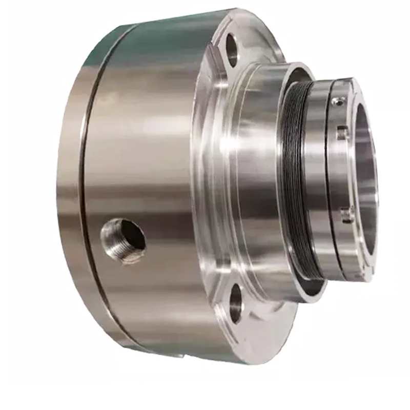
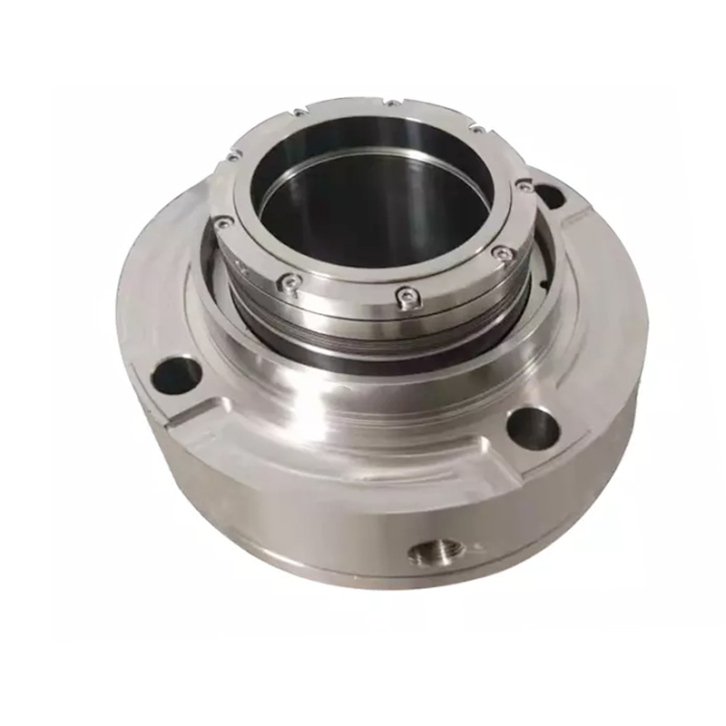
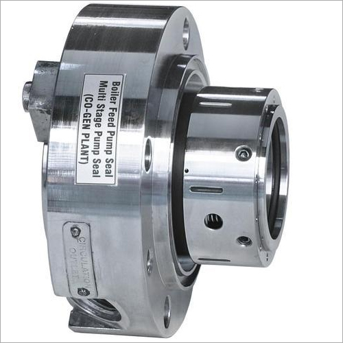
boiler feed pump mechanical seal free sample

Zigong Ke Yu Seal Science and Technology Co.,LTD located in hightech industry of zigong city in sichuan province. We are large manufacturer and exporter of high pressure,high temperature, high speed mechanical seal. Our products widely used in KSB pumps, Grundfos pumps, Flowserve pumps, etc. And our mechanical seal can exactly replace original mechanical seal in sharpe agitator, ekato agitator, lightnin agitator, sardik agitator, mut agitator, mixpro agitator etc. We design and manufacture mechanical seal up to 60 bar, 3000rpm, 300C°in different material of constructions like ss316/316L,ss304, Sillicon Carbide, Tungsten Carbide, Carbon, Viton, NBR, EPDM ,PTFE, etc. From pumps to reactor for various application. We can also provide ODM and OEM precision machined parts according to your drawings or design requirements. For exmple,customized shaft, shaft sleeve, as well as a variety of high-precision, high request products. Materials that can be produced include stainless steel, titanium and any other metal material of different grade.
The cylinder friction of the sealing parts, the actual sealing gap friction and the heat conduction of the hot pump components in the direction of the sealing housing.
daß die Wassertemperatur im Dichtungsbereich nicht über ca. 50 bis 65°C ansteigt.A trouble-free function of the mechanical seal depends on the fact that the
Instead of increasing the effort required for cooling with increasing requirements, the conditions responsible for the problems described can be used if a so-called gas seal is used instead of a liquid-lubricated mechanical seal. For the operation of such a seal, it is only necessary to ensure that the medium to be sealed is in vapor form on the mechanical seal. Since this medium is hot water, which would already evaporate at the pressure prevailing outside the centrifugal pump, only a comparatively small effort is required to meet the current condition. A partially external cycle is no longer necessary.
einen Gegenring 4, der mit der Welle 5 der Kesselspeisepumpe umläuft.The mechanical seal is formed by a mechanical ring 1 , which is arranged in a cover 3 that closes the housing 2 of the boiler feed pump, and a counter ring 4 , which rotates with the shaft 5 of the boiler feed pump.
Dichtspalt zwischen Gleitring 1 und Gegenring 4 allein gasförmiges Medium.A pump device 7 designed as a screw conveyor is connected upstream of a sealing chamber 6 surrounding the mechanical seal 1 , 4 . The pump device 7 exerts a conveying action in the direction of a space 8 which is connected downstream of a throttle gap 9 which closes the interior of the boiler feed pump. The conveying effect has the result that medium entering the area of the pump device 7 from the interior of the centrifugal pump can only enter the sealing chamber 6 with a loss of pressure. This pressure loss is so high that any medium entering the pump device 7 as hot water is put into the vapor phase. Thus, only gaseous medium gets into the sealing gap between slide ring 1 and counter ring 4 .
der Gleitringdichtung 1, 4.A targeted drop in pressure in the sealing chamber 6 can act as a support. This can be achieved by a defined leakage of the mechanical seal 1 , 4 .
ansammelt, zur Saugseite der Kesselspeisepumpe hin abgeführt.Relief water, which accumulates in space 8 , is discharged to the suction side of the boiler feed pump via a bore 10 provided in the housing 2 and an adjoining — here only indicated — line 11 .

Wear rings are an essential component of the subject pump’s design and application. Typically, the pump impeller will have wear ring surfaces that are either renewable or integral; the casing will have stationary wear rings that mate with each impeller rotating wear ring. The radial running clearance between the two rings affects the internal recirculation of the process water in the pump. The amount of fluid that recirculates across the ring clearance has a direct effect on the pump’s efficiency.
In a construction using C-6 material there will typically be 400 series stainless steel wear rings in the pump. The pump manufacturer will harden the 400 series rings so that there is at least a 50 Brinell hardness differential between the impeller and casing wear rings which helps prevent galling between the two rings during operation. Running clearance on these rings can be quite high at an elevated temperature. API 610 recommends running clearances greater than the pump OEM manufacturer’s clearances, especially as process temperature increases. High running clearances can provide improved reliability over time. As dry running a pump with metallic rings installed can cause catastrophic failure to the pump in less than one minute, special measures should be taken to prevent dry running the pump when metallic wear rings are installed.
Today there are a number of options on wear ring materials for customers to choose from in lieu of the traditional metal-to-metal ring combinations. Over the past two decades there have been many composite thermoplastic wear ring materials that have been introduced to the market. These composite materials are typically used on the stationary casing wear ring component. The composite material is installed inside of the metal ring as shown here. Composite material is also recommended for the stationary center bushing component on the API 610 BB3 design. Most composite rings can operate up to 500°F, allowing it to operate in most Boiler Feed Water applications.
With a composite wear ring on the stationary ring, running clearances can be taken to much tighter values, when compared to a metal-to- metal ring clearance. For example, the API 610 requires a .020” diametrical running clearance on a ring that is 8.000 inches to < 9.000 inches in diameter. Composite wear rings can accommodate a .011” diametrical running clearance on that same ring dimension. This ultimately improves the efficiency of the pump. In addition to its ability to run a tighter clearance, the composite ring also has a low coefficient of friction. This low coefficient prevents excessive heat buildup during an upset or temporary dry run condition. There are many case studies in the industry which show customers who have prevented a catastrophic and costly pump failure by having composite stationary wear rings installed on their pumps.
Composite rings come at a price. They can often add $15,000-$25,000 to the cost of a large API 610 BB3 pump. I will add that not all composite wear rings materials are created equal. Some will have different radial thermal expansion properties than others. It is encouraged that a pump subject matter expert conduct research before one decides on the type of composite ring material to use. Finally, caution is strongly recommended if using composite wear rings material in fluids with high solids content. If there is heavy scale or high solids in the boiler feed water, it is best to stay away from the composite ring materials. The thermoplastic base material can wear quickly in a high solids environment.

The outstanding advantage of the DF-SAF(P)I is that it puts an end to the electrical corrosion that has a destructive effect on the silicon carbide rings. Even without conditioning the feed water, e.g. by injecting ammonia, the seal with coated seal face and seat achieves a significantly longer service life. Complicated repair jobs and expensive downtimes are both minimized as a result.
Before the DiamondFace coating was used, it was tested under scientific conditions and with the original fluid as part of a project undertaken jointly by EagleBurgmann and the Technical University of Graz in Austria. After more than 10,000 hours of continuous operation without any signs of electrical corrosion on seal face or seat, it was then possible to go on to successful practical application of the seal solution together with E.ON.

They serve to feed a steam generator such as a boiler or a nuclear reactor with a quantity of feed water corresponding to the quantity of steam emitted. Today, all boiler feed pumps are
Until 1950, the average pressure in the outlet cross-section of the pump (discharge pressure of the feed pump) was in the 200 bar region. By 1955 the average discharge pressure had risen to 400 bar. The mass flow rates were in the region of 350 tonnes/h in 1950, compared to 3200 tonnes/h (in some exceptions up to 4000 tonnes/h) today. Boiler feed pumps operate at fluid
Feed pumps for 1600 MW nuclear power stations are constructed for mass flow rates of up to 4000 tonnes/h and feed pump discharge pressures of 70 to 100 bar.
Until 1950 approximately, boiler feed pumps were made of unalloyed steels; since then they have been made of steels with a chrome content of 13 - 14 %. This change of materials was made necessary by the introduction of new chemical feed water compositions. The development of highstrength, corrosion and erosion resistant martensitic chrome steels with good anti-seizure properties as well as the continuous development of all pump components (bearings, shaft seal, pump hydraulic system, etc.) paved the way for present-day boiler feed pumps with rotational speeds of 4500 to 6000 rpm.
The mass flow rates of centrifugal pumps rose rapidly in conjunction with the rise of unit outputs in power stations. Today"s full load feed pumps for conventional 800 to 1100 MW power station units are constructed with four to six stages with stage pressures of up to 80 bar. Feed pumps for 1600 MW nuclear power stations are of the single-stage type.
In the case of conventional power stations above 500 MW full load feed pumps are increasingly driven by steam turbines. In most cases condensing turbines running at 5000 to 6000 rpm are used.
Electric motors usually drive part load feed pumps, both in fossil-fuelled and in nuclear power stations. Speed control of electrically driven feed pumps is effected by either fluid coupling (e. g. variable speed turbo couplings) or by electrical closed-loop control systems by means of thyristors (up to a drive rating of approximately 18 MW in 2011).
The low-speed booster pump is usually driven by the free shaft end of the turbine via a step-down gear or directly by the free end of the electric motor. See Fig. 2 Boiler feed pump
The single or double suction booster pump serves to generate the necessary NPSHR of the system for the high-speed boiler feed pump connected downstream. Fig. 3 Boiler feed pump
Two aspects of deciding between a ring-section and a barrel pull-out pump are described below:The smaller the mass flow rate and the higher the pressure, the higher the material and manufacturing costs of barrel pull-out pumps. This does not apply to the same extent to ring-section pumps.
Barrel pull-out pumps have some advantages over ring-section pumps when it comes to repairing a pump installed in the system. If a rotor has to be replaced, the barrel (see Pump casing) can remain installed in the piping. This is significant with regard to the
In the case of nuclear power stations, single-stage feed pumps with double-entry impeller (see Double-suction pump) and double volute casing are usually adopted. See Fig. 6 Boiler feed pump
Cast pressure-retaining casing parts are increasingly replaced by forged parts. As an example, such a feed pump could be designed with a flow rate of about 4200 m3/h and a head of about 700 m at a rotational speed of 5300 rpm. See Fig. 5 Boiler feed pump
Heads of reactor feed pumps are in the region of 800 m for boiling water reactors and 600 m for pressurised water reactors. The flow rates are about twice as high as those of a comparable boiler feed pump in a fossil-fuelled power station.
For boiler feed pumps two factors have to be considered regarding the wall thickness of the casing: the pressure loads and the different temperature conditions it needs to withstand. These two criteria are satisfied by adopting a high-strength ferritic casing material which enables the wall thickness to be kept thin enough to avoid any overloads as a result of temperature fluctuations, yet of adequate thickness to guarantee the requisite safety against internal pressure.
Barrel casingThe casings of barrel pull-out pumps and barrel casing pumps are usually made of unalloyed or low-alloyed ductile forged steel. Deposit welding is used on all surfaces in contact with the feed water to coat them with corrosion and erosion resistant material.
In order to weld the pump into the piping, an adapter must be provided if the materials of the nozzles to be connected are from different material groups.
The discharge-side (discharge pressure containing) barrel cover is fastened by means of large non-torqued studs. Sealing is provided by a profile joint which is pressurised purely by the prevailing pressure (of up to several 100 bar) without any external forces acting on it. See Fig. 7 Boiler feed pump
Ring-section pumpsThe casings of ring-section pumps are preferably made of forged chrome or carbon steel plated with austenitic (iron solid solution) material.
The sealing element between the individual stage casings (see Stage) seals off by metal-to-metal contact, the individual casings being clamped together axially by tie bolts between the suction and discharge casings (see Pump casing).
A common feature of barrel pull-out pumps and ring-section pumps is that the greater the wall thickness, the greater the thermal stress caused by thermal shocks, which in turn reduces the service life of the pump. The provision of injection water at a pressure situated between the suction and discharge pressure of the pump is a frequent requirement. This is taken care of by tapping water from one of the pump stages of both barrel pull-out pumps and ring-section pumps.
Tapping a stage of a boiler feed pumpIn the case of ring-section pumps, a partial flow at an intermediate pressure can easily be tapped through a tapping nozzle in one of the stage casings.
In the case of barrel pull-out pumps, the inside of the barrel is divided into three pressure zones so that a partial flow at the required intermediate pressure can be led off directly to the outside. See Fig. 4 Barrel pull-out pump
The sealing function is taken care of by a profile joint between the discharge and the tapping pressure, and by a metal-to-metal joint between the tapping and the inlet pressure. See Fig. 7 Boiler feed pump
The pump shaft of boiler feed pumps has a very small static deflection as the bearings are spaced as closely as possible, the shaft diameter is relatively large and thevibrations and runs smoothly (seeAxial thrust) which have to be absorbed by the balancing device.
The rotors of single-stage reactor feed pumps are even stiffer than those of boiler feed pumps, and their static deflection is smaller than that of multistage boiler feed pumps.
The magnitude of this axial thrust depends on the position of the operating point, on the characteristic curve, the rotational speed and the amount of wear on the internal clearances (see Controlled gap seal). Additional disturbing forces can arise in the event of abnormal operating conditions, e.g. cavitation.
On larger boiler feed pumps the axial forces at the pump rotor are balanced by means of a hydraulic balancing device through which the fluid handled flows. The balancing device is often combined with an oil-lubricated thrust bearing (see Plain bearing). As this balancing device absorbs more than 90 % of the axial thrust, a relatively small thrust bearing can be used. The balancing device may comprise a balance disc with balance disc seat, or a balance drum or double drum with the corresponding throttle bushes.
Axial thrusts arising in reactor feed pumps with double-entry impeller (see Double-suction pump) are balanced hydraulically; residual thrusts are absorbed by an oil-lubricated thrust bearing. See Fig. 6 Boiler feed pump
Radial forces arise from the weight of the rotor, mechanical unbalance or hydraulic radial thrust. The radial forces are balanced by two oil-lubricated radial bearings as well as by throttling clearances through which the fluid handled flows in axial direction. Such throttling clearances are located at the impeller neck on the impeller inlet side, or in the case of multistage boiler feed pumps for conventional power stations on the discharge side of the impeller (interstage bush) and at the balance drum. If the rotor is in an off-centre position, a re-centring reaction force will be generated in these clearances, which largely depends on the pressure difference and the clearance geometry (LOMAKIN effect).
The LOMAKIN effect is severely reduced when, due to abnormal operating conditions, the feed water in the clearance is not in a purely liquid phase (see Cavitation).
The hydrostatic action of the clearances contributes more to reducing shaft deflection than the mechanical stiffness does. The system is designed in such a way that operating speed always remains well away from the critical speed of the rotor, allowing hydraulic exciting forces (particularly in low flow operation) to be absorbed in addition.
Common shaft seals for boiler feed pumps are mechanical seals, floating ring seals and labyrinth seals. Gland packings are less common these days. (Also see Shaft seal).
Transient or low flow operating conditions cause additional loads on boiler feed pumps. This leads to additional stresses and strains as well as to deformation of components with various consequences on their functionality.
Nowadays, almost all boiler feed pumps must be able to handle both cold starts (high-temperature shock loads) and semi-warm starts without any damage. In these start-up procedures hot feed water abruptly flows into the cold pump, which results in the inner components heating up much faster than the pressure boundary. Depending on the frequency of starts and the gradient curves of pressure and temperature (load cycles) this can shorten the service life of the pump.
Contact between parts of thestator cannot, generally, be ruled out as narrow clearances are used as controlled gap seals This applies to the impeller neck on the impeller inlet side, the discharge-side clearance between impeller,
In operating conditions with a very low or zero flow, e.g. in the turning gear mode of a turbine-driven boiler feed pump, temperature layers establish in the fluid handled, which may cause deformation of the rotors and, after a slight delay, also of the non-rotating components. Once the clearance gaps are closed the rotor will be subjected to a significantly higher friction moment, leading to overload of the turning gear and to standstill of the pump. In this case, the temperature will no longer be equalised at the rotor, which will further aggravate the rotor deformation.
This can result in several hours of downtime for the pump. Usually the only remedy is to let the machine cool down to reduce or eliminate the critical temperature layers and the deformation.
Avoid large differences in temperature in and on the pumpThermally separate the cold areas (shaft seal area) from the area through which the hot fluid passes (hydraulic system and balancing device) by means of an insulation chamber system; provide a thermal seal to prevent convection flows and special thermosleeves.
The above measures are frequently used for barrel casing pumps (barrel pull-out pumps) as their outer dimensions, wall thickness, drive (turbine with turning gear) and operating modes are considered more critical than those of ring-section pumps. If possible, these measures are always automated to safeguard the availability of the pump set.
A minimum flow valve (automatic recirculation valve) ensures a minimum flow rate and thus prevents damage which could occur in low flow operation as a result of either an impermissible increase in temperature leading to vaporisation of the pump content or low flow cavitation.

The shaft seal is a sealing element which seals the rotating shaft, of a centrifugal pump where it passes through the non-rotating pump casing reducing fluidleakage to atmosphere or the entry of air from outside to a certain level, and keeps wear of the sealing faces as low as possible.
Pumps are specially designed and manufactured to cater for a whole range of different applications. This process takes into account aspects such as resistance to the fluids handled, temperature and pump pressure. The appropriate seal type for the individual pumping requirements is chosen from a wide variety of different shaft seals.
The design is based on one of the two following principles: sealing by means of a narrow radial gap (parallel to the shaft axis) or a narrow axial gap (at a right angle to the shaft axis). For both sealing principles, the gaps may either employ a contact or non-contact design.
If only non-contacting controlled gap seals are used, a considerable amount of leaking fluid can always be assumed. This sealing system is therefore less suitable for environmentally harmful fluids handled.
Shaft seals are by their nature susceptible to leakage, and with some types leakage is actually essential to ensure proper sealing functioning. The suggestion that a seal shaft provides "zero leakage" is therefore misleading. However, depending on the seal type chosen, the amount of leakage
can vary considerably. A volute casing pump with a circumferential speed at the sealing area of 20 m/s and a pressure to be sealed of 15 bar which uses a gland packing for sealing has a leakage rate of about 5 – 8 l/h, while the leakage rate of a mechanical seal used under the same conditions is only approx. 6 cm3/h (0.006 l/h).
The leakage rate of 4 to 6000 l/h for a boiler feed pump sealed by a floating ring seal is particularly high; in this case, the diameter to be sealed is 200 mm and the pressure 40 bar, the
Due to differences in pump designs the individual seal types are not necessarily suitable for every type of application. The type of seal to be employed depends on the sliding velocity, the pressure to be sealed and the fluid temperature.
In the case of contact-type dynamic shaft seals, the parts to be sealed move relative to each other. For this reason lip-contact and line-contact shaft seals (e. g. lip seals) are only suitable for use with very low pressure differences such as those occurring when sealing against bearing oil, and are usually not adjustable.
The packings can be adjusted and are suitable for higher pressures and circumferential speeds than lip seals. Different packing variants are used depending on whether the pump is run in suction head or suction lift operation, or whether it handles clean or contaminated fluid.
As the leakage with gland packings is relatively high compared with mechanical seals, the former are mostly employed for environmentally friendly fluids only.
If the pump is used in suction lift operation, a barrier fluid line and a lantern ring fitted after the first packing ring ensure that air cannot enter via the packing. Provided the pump handles a clean fluid, this barrier fluid is supplied via the pump"s See Fig. 5 Shaft seal
As the barrier fluid pressure is higher than the pump pressure, a certain amount of the barrier fluid mixes with the fluid handled inside the pump, so that compatibility between the barrier fluid and the fluid handled should be ensured.
Unlike gland packings, mechanical seals have a sealing gap which is positioned at a right angle to the shaft axis. These shaft seal designs are also called axial or hydrodynamic mechanical seals. Compared with gland packings, they require less space and no maintenance.
Mechanical seals are well-suited for sealing low and high pressures and circumferential speeds. The risk of inappropriate operation is therefore very low.
However, considerable disadvantages arise through wear caused by abrasive fluids (see Abrasion). As is the case with gland packings, clean barrier or flushing fluids (e. g. cleaned by means of cyclone separators) help to keep abrasive particles away from vulnerable seal faces.
Pressed together by hydraulic and mechanicalforces, two seal faces slide relative to each other during operation. The sealing gap lies between these precisely machined seal faces and is filled with a lubricating film, generally a liquid. The sealing gap width (i.e. the distance between both seal faces) is influenced by various factors, including the seal faces" surface quality (i.e. how rough or smooth they are) and the sliding velocity.
Leakage from mechanical seals is very low; the fluid leaks into the atmosphere in the form of vapour or droplets. To calculate the mechanical seal"s leakage rate, a gap width of under 1 μm is normally assumed. Thanks to this extremely narrow gap, the leakage rate for mechanical seals is considerably lower than that for shaft seals with radial gaps.
A further important differentiating feature is that seals can be unbalanced and balanced. In the case of unbalanced mechanical seals, the seal face is exposed to the complete pressure to be sealed.
If the k value becomes smaller, the seal face loads are reduced. For this reason, only balanced mechanical seals are employed in high-pressure and high-velocity applications.
A low k value results in both an improved lubricating film and a higher leakage rate. However, an excessively low k value may in extreme cases cause the complete separation of the seal faces resulting in a loss of the sealing effect.
Alongside the hydraulic closing force, spring forces provide an additional axial force acting on the sealing gap. The springs can employ an open or enclosed design and be in contact with the fluid handled or not; they may or may not transmit torque.
The friction losses generated are lower than those of gland packings. Heat is generated in the shaft seal housing due to friction; depending on the amount produced, it can be dissipated either via convection from the seal housing to the atmosphere or via forced circulation through an externally installed heat exchanger.
Frequently used designsSingle, unbalanced mechanical seal as a typical example for a centrally arranged, conical single spring: The variant shown here is for "dead end" installation, i.e. there is no additional fluid circulation in the mechanical seal area.
Unbalanced mechanical seals are used for pressures of up to max. 15 bar and sliding velocities of up to max. 15 m/s. In general, a sufficient proportion of friction heat generated in the sealing gap can be transferred to the fluid handled and dissipated from the shaft seal housing to the atmosphere via convection. If the fluid handled is cold, the friction heat is absorbed by the fluid itself. One variant is the rubber bellows seal (bellows-type mechanical seal).
Unbalanced mechanical seal with stationary spring assembly: this design is used for higher sliding velocities and ensures the springs can reliably fulfil their task (rotary spring assembly would entail a risk of broken springs due to high centrifugal forces).
Varying spring arrangements are just one example of the distinctive features represented in the wide range of mechanical seal designs tailored for various operating conditions.
In the case of "back-to-back" arrangements, a barrier fluid is fed into the space between the two mechanical seals. Its pressure should be approx. 10 %, and at least 2-3 bar, higher than the pressure of the fluid handled by the pump.
This barrier fluid ensures that the fluid handled does not leak into the atmosphere. Before considering this arrangement, it should be established whether a zero-leakage pump such as a canned motor or mag-drive pump would be more suitable for the application.
As the barrier fluid absorbs the friction heat generated by the two mechanical seals, it must be circulated, i.e. removed from the seal cavity, cooled and returned to the seals.
The barrier fluid pressure is generated by a barrier fluid system (thermosyphon vessel) or pressure booster. In the case of tandem seals, the space between the seals is flushed by unpressurised quench liquid (quench). If the leaking fluid handled by the pump has a tendency to crystallise when in contact with air, a seal arrangement comprising two rubber bellows seals should be used. It is important that the quench liquid and fluid handled are compatible.
Instead of using an outboard mechanical seal, it is also possible to install a simple sealing element such as a lip seal or packing ring. It is fitted as a back-up seal for the main seal to prevent leakage (e. g. in the case of hazardous fluids) and to safely and reliably dissipate heat.
Tandem seals are employed when a high internal pump pressure requires distribution to two mechanical seals. The barrier fluid pressure level then lies between the pressure to be sealed and the atmospheric pressure. The pressure handled by the inboard seal corresponds to the difference between the pressure to be sealed and the barrier fluid pressure; the pressure handled by the outboard seal corresponds to the difference between the barrier fluid pressure and the atmospheric pressure. The barrier fluid must circulate in order to dissipate the friction heat generated by the seals.
These mechanical seal types are used in the boiling or pressurised water reactors of nuclear power stations and are installed in main coolant pumps to seal extremely high pressures.
The pressure must be distributed via an auxiliary system, e.g. a three-stage cascading system of throttles arranged in the seals" bypass lines. A defined amount of water flows via the bypass line. Pressure is thus reduced by approx. 33 % at each throttle. The reduced pressure at each stage"s output is the operating pressure for the next stage"s input. This throttling and recirculation of the barrier fluid ensures the pressure is reduced and the friction heat removed from the sealing stages.
In the case of boiler feed pumps, seals have to cope with high sliding velocities, heat transfer from the fluid handled and the heat generated by friction.
The sealing gap temperature is generally higher than the fluid temperature in the seal housing. The latter can be kept well below 100 °C by circulating the fluid through to an external cooler by means of suitable pumping devices inside the pump. Pumping screws, holes in the shaft protecting sleeve or small pumping discs serve as pumping devices.
Magnetic filters ensure that the circulated water is absolutely clean. With high-specific speed pumps,a venting tank is essential to reliably remove any air from the circulation liquid.
Detrimental dry running of the mechanical seal may occur if the pump is operated without liquid fill and in the event of a major ingress of gas, a high gas content or the evaporation of the fluid handled. Due to its low density, the gas always tends to move to smaller diameters which is the sealing gap of seals in most cases. The presence of air in this space leads to dry running and also impedes sufficient heat dissipation from the sealing gap resulting in thermal overload of the seal faces and mechanical seal failure (heat stress cracks) within a very short time.
External cooling circuits are not used if the heat losses generated by the seal can be dissipated to the atmosphere via free convection and heat radiation.
Other forms of cooling comprise a fan impeller mounted to the pump shaft to intensify convection (forced convection). In both cases the seal housing is provided with fins, at a right angle to the shaft axis (without fan impeller) see Fig. 16 Shaft Seal, and parallel to the shaft axis (with fan impeller).
In the case of uncooled mechanical seals operated at high temperatures, the temperature in the sealing gap is generally higher than the temperatures in the sealing gaps described so far. This means that the boundary between the liquid and vapour phase in the sealing gap inevitably shifts towards the sealing gap inlet, increasing the risk of insufficient lubrication.
The sealing gap width between the stationary component and the rotating component is designed to be as narrow as possible in order to minimise leakage. However, it is important to ensure that the parts do no rub against each other. Leakage on a rotating shaft is slightly lower than during standstill.
The fluid flowing through the gap allows the pressure to be reduced in relation to the atmospheric pressure. On throttling gaps and floating ring seals this is achieved in the gap due to fluid friction and due to flow losses when the fluid enters or leaves the gap.
Floating ring sealThe major advantage of floating ring seals is the fact that the components are not in contact. However, the time and costs required to provide the barrier condensate, its treatment and relevant control equipment are substantial.
The floating ring seal consists of several short throttling rings fitted in succession which can move in a radial direction and centre themselves automatically due to the pressure distribution on the ring. A cold barrier condensate injected into the seal ensures that hot water from the pump does not escape to the atmosphere (controlled system). As long as the pump is in operation or under pressure, barrier water supply must be ensured.
The floating ring seal is occasionally employed in boiler feed pumps. Its barrier condensate quantity can be controlled via the barrier condensate"s pressure and temperature difference.
(Δt control), the difference between the temperature of the barrier condensate at the outlet and that of the injection condensate is defined. In the case of boiler feed pumps, the amount of feed water escaping from the inside of the pump is very low, while penetration of cold water into the pump can be ruled out.
For differential pressure control (Δp control), the difference between the injection pressure and the inlet pressure is defined. A very small amount of barrier condensate flows into the pump. This puts high demands on the cleanliness and gas-free condition of the barrier condensate required to prevent the main circuit from being contaminated.
Labyrinth sealThe labyrinth seal is a firm throttling bush with a circular groove profile. As radial movement is impossible with this type of seal, the diametral clearance must be wider
Centrifugal sealThis type of shaft seal generates pressure itself in order to counteract the differential pressure to be sealed; it is frequently backed up by a standstill seal. Designed as
spring-loaded mechanical seal, it is opened by centrifugal forces at very low speeds and thus protected against wear. See Fig. 20 Shaft sealThe actual centrifugal seal (fitted as an auxiliary impeller using a liquid ring at the outer diameter) operates contact- and wear-free.
Pumping ring/screwOptimally designed pumping rings/screws (thread pitch of the stationary part directed against the pitch of the rotating part) can also generate a back pressure capable of balancing the pump"s internal pressure when the pump is running. The pressure balance achieved this way depends on the rotational speed, thread length, gap width and mean gap diameter.
Hydrostatic sealDue its design, proper functioning of the hydrostatic seal as a non-contact seal is only ensured at pressures from 20 bar. The pump drive must not be started until this pressure level is reached.
The gap with which the seal operates may be very narrow, but it is finite, and as such exhibits a considerable leakage rate (p = 160 = 160 bar, n = 1.500 = 1500 rpm; sealing diameter at 260 mm, Q = 800 = 800 l/h). It is therefore necessary to back up the hydrostatic seal with a low-pressure seal that provides sealing to atmosphere.
See Fig. 22 Shaft sealDue to the hydrostatic seals’ operating limitation at low pressures, they have been replaced with hydrodynamic mechanical seals in many nuclear power stations.
Static contact seals include O-rings. These are moulded seals and are defined as "rings with circular cross section made of elastic materials; they seal through the effect of slight bracing during installation, intensified by the operating pressure" according to DIN 3750. Their symmetrical cross-section rules out incorrect installation.
O-rings are employed on all the shaft seals described here. However, they can only be used as static sealing elements or to seal areas where slight axial movement is occasionally required.
The majority of O-rings used on mechanical seals are elastomer rings with a shore A hardness of 70 to 90. These O-rings are used for sealing between the shaft sleeves and the shaft, and between the primary ring or the mating ring and the respective components they are connected with. They ensure that the spring-loaded seal component can follow small axial shaft movements.
Their significance is often underestimated: ultimately, each shaft seal is only as good as its O-ring. O-rings must be matched to the fluid handled, cover a defined temperature range and provide good ageing resistance. Moreover, it is important to use a high-quality O-ring grease which meets the operating requirements. Besides providing long-term lubrication, the grease must be compatible with the fluid handled and must not attack the O-ring.
Elastomers which swell less than 10 % in the operating fluid and do not chemically react with the fluid handled are suitable for use as a mechanical seal"s secondary seal. A number of elastomers are available for this purpose which react differently in a reference oil with regard to temperature

In the beginning, water ran freely over the Earth. Then, man made pumps to make water run where he wanted it. Then came leaks. Then, man made pump seals. And as time went on, man still continued to struggle with leaking pump seals.
For those who are new to pump maintenance and repair, mechanical seals can be intimidating—given their reputation as temperamental devices that fail frequently. In fact, they are simple devices that are often misapplied and sometimes poorly installed or used on pumps that are ill-suited for the application. For many applications, mechanical seals are robust enough to tolerate less-than-optimal handling and operating conditions. For more demanding applications, though, everything must be right.
It is important to review how a pump mechanical seal works. First, its main components are the rotating and stationary face rings that form the primary seal (Image 1). The face rings have flat, precision-smooth contact surfaces that are held in tension against each other by mechanical springs.
The rotating face ring and its assembly have to be sealed to the shaft. The stationary face ring has to be sealed to the housing. These two sealing points are called secondary seals and typically use elastomer O-rings or boots (Image 2).
Selecting the proper materials for the primary and secondary seal components is important. For common water pumping applications, carbon-ceramic face material and Buna-N secondary seals are standard and work well. Alternate materials work better for pumping sewage or strong chemicals, so many technicians seek outside help on these applications.
By following a few precautions, it is not difficult to install pump mechanical seals during the repair process. For example, to ensure the elastomer secondary seals will slide into place undamaged, always use the proper lubricant. Some seal providers offer water-soluble lubricants designed for this purpose. Make sure the lubricant is water-soluble (except with oil-filled seal chambers), so that it will be washed away by pump operation.
In all cases, avoid damaging the elastomer secondary seals on the edges of shaft shoulders, keys or housings. A good way to accomplish this is to wrap a sheet of mylar paper around the shaft to protect the seal as it is slid into place.
While the amount of tension the seal spring assembly applies can be a concern on some special applications, the tension adjustment on common utility pumps is preset by the pump and seal design. Just observe during disassembly if there are any tensioning provisions and, if so, document the measurements.
When a seal leakage problem occurs, carefully inspect the seal to determine the cause. Is it leaking at the primary seal or at one of the secondary seals? The wear pattern of primary seal faces should be smooth and slightly shiny, and the elastomer secondary seals should be pliable but not soft. The shaft and housing contact surfaces should be corrosion free; corrosion at those contact points would indicate a leak.
If the cause of a problem is difficult to determine, many value-added seal providers can analyze seal failures, ask critical questions about the application and recommend products that will perform best. Their prices may be more than some alternatives, but their value added is the knowledge to spec the right product.
If unsure about how to find a good, value-added seal provider, do an internet search for “industrial pump seals” in the required zip code. In major metropolitan areas, there are probably three or four likely prospects. Ask each of them for a seal for a boiler feedwater pump (or other tough application). If they only ask for the pump ID or the dimensions but not the temperature, pressure or other application parameters, they probably will not be much help. Users may get a great price, but on the wrong product.
Eugene Vogel is a pump and vibration specialist at EASA, Inc. in St. Louis, Missouri. He may be reached at 314-993-2220. EASA is an international trade association of more than 1,800 firms in nearly 70 countries that sell and service electromechanical apparatus. For more information, visit easa.com.

Chesterton is the world leader in design innovation of split seals. Our innovative split seals have been used to seal thousands of process-critical pieces of rotating equipment with exceptional results and many years of leak-free operations.
Chesterton was the first company to offer commercially-viable split seals for plant-wide use, which revolutionized pump sealing across industries. Since that time, we"ve launched a number of innovative split seal designs now used as a standard by companies around the globe. We offer shaft diameters ranging from 25-914 mm (1-36 in.)
A split seal has components split into two equal halves which are secured as one unit on the seal shaft. The major advantage of the split seal design is that it allows you to install the seal with no dismantling of the pump (or equipment)—an enormous time-saver! Chesterton"s split seals offer virtually leak-free performance. This leads to improved safety and environmental compliance and nearly eliminates sleeve wear, and flush water usage, among many benefits.
A German power plant experienced premature wear and excessive seal corrosion in its boiler feed circuit and flue gas desulfurization slurry pumps. By upgrading the performance of the pump seals and implementing a high-performance seal maintenance, repair, and part stocking program, unplanned pump shutdowns were eliminated and mean time between repairs improved from 20 to 40 months.
As with all rotating equipment, pump seal wear is a constant factor requiring continual monitoring, maintenance, repair, and replacement to keep pumps operating as specified. In coal-fired power plants, mechanical seals are utilized in pumps throughout many processes.
Mechanical seals consist of a stationary primary element that is fixed within the pump housing and a rotating mating element fixed to the shaft. Precisely machined, these two components are pressed together, meeting at a wear face, while the extreme tolerances between the two elements minimize leakage. The seals rely on a certain amount of leakage to lubricate the moving surfaces. The rotating element is supported on an extremely thin lubricating film, typically 0.25 microns in thickness.
These seals are influenced by a number of factors, including temperature, pressure, vibration from pump shaft misalignment, and quality of the pumped fluids. Coal-fired plants have many processes that contain abrasives and solids within the fluids being pumped. These insoluble liquids are hard on mechanical seals because they create added abrasion and erosion of the components. The particles can get into the mechanical seals’ O-rings and springs, causing these components to go rigid and no longer able to move with the shaft movements and pressure deflections.
In coal-fired plants, mechanical seals (Figure 1) can be found in the main heat cycle for pumping raw feedwater, boiler feedwater, condensate, and the cooling water that supports the condensate system. They are used in secondary pumps, fire suppression systems, and service and wastewater applications. Mechanical seals are also employed in the movement of limestone slurry for the flue gas desulfurization (FGD) scrubber system.
At one of Germany’s largest lignite-fired power plants, boiler feed circuit pump seals and FGD slurry pump seals were negatively impacted, experiencing a significant reduction in mean time between repair (MTBR), ultimately resulting in unplanned pump shutdowns. The pumps experienced premature seal wear and excessive seal corrosion as a result of adverse reactions to feedwater treatments, coupled with inadequate maintenance and part stocking issues.
The core of this thermal power generating plant, the boiler feed circuits rely on high-speed, high-performance pumps to keep the water moving through the systems. Each boiler feed circuit has two high-speed, high-performance pumps feeding the boiler, and approximately 100 secondary pumps along the feed circuit. Plant-wide, the boiler circuits have 12 high-performance pumps and approximately 600 secondary pumps. Each of these pumps has mechanical seals and the high-performance boiler pumps have two mechanical seals for each pump.
In high-purity boiler feedwater/combined oxygen treatment processes, with high-speed, heavy-duty pump applications in boiler feed circuits, minute electrical potentials develop, which cause electrostatic corrosion on the mechanical seals. The material of the mechanical seal itself becomes degraded, resulting in a shortened lifespan. This condition is due to chemical reactions from combined oxygen treatment procedures of the feedwater initiated to reduce corrosion in the boiler, resulting in the creation of electrical voltage.
The high-performance boiler feed circuit pumps are integral to the operation of any thermal power generating plant. If just one of these pumps fails, that boiler feed circuit would be running at 50% operation, or could be potentially shut down. Failure of the mechanical seal is the primary cause of pump failure. This is just what occurred at this plant, where boiler feed pump seal integrity was lacking, causing unplanned pump shutdowns.
The German plant has 60 main feed pumps in the FGD circuit—with an additional 250 to 300 secondary pumps—for a total of 310 to 360 pumps involved in plant-wide FGD. The abrasive and corrosive wet limestone slurry put high corrosive demands on both pumps and seals at the plant. FGD feed pump seals at the plant failed due to metal erosion and corrosion issues, resulting in a lack of seal component flexibility. The corrosion came from the calcium sulfite, and the erosion from the fluid velocity in close to the mechanical seals.
John Crane, whose seals were originally installed in the plant’s boiler feedwater pumps, was selected to implement a comprehensive program to isolate the cause of the premature pump seal degradation in both boiler feed circuit pumps and FGD slurry pumps; engineer a mechanical solution to extend longevity for the seals; implement a system to monitor the ongoing condition of the feed water; and establish a structured maintenance, repair, and part stocking regimen for both boiler feed circuit pump and FGD slurry pump seals.
Boiler Feed Circuit Pump Seals. John Crane thoroughly investigated the condition of the boiler feed circuit pump seals, and developed a strategy to mitigate the problem. This included specifying and installing specific components for the boiler feed seals of this plant; implementing an ammonia dosing system, which feeds an ammonia solution around the mechanical seal to increase electrical conductivity of the feed water; and putting into place a control system to monitor the electrical conductivity of the feed water, integrated into the pump programmable logic controllers.
The solution changed the conductivity of the water around the seals and included changing the seal face materials. The result was more reliability and longevity. The project has been underway for some time and has doubled the life of the seals.
The feed pump seals in place are heavy-duty John Crane Type 270F O-ring pusher cartridge seals for boiler feed circuit applications. They are designed for critical high-pressure, high-temperature, and high-shaft speed applications. The face and seat are computer-engineered for optimum distortion control leading to high reliability and long operating life.
These seals can handle temperature limits from –40F to 500F (–40C to 260C); pressure limits up to 1,000 psig (69 barg); and speed limits up to 4,000 feet per second (60 meters per second). Advanced computer-designed faces maintain optimum performance under all temperatures and pressures.
2. Available as a single or double seal, the Type 5860 mechanical seal is designed to operate in the harshest abrasive slurry environments. Courtesy: John Crane
FGD Slurry Pump Seals. Together with the local pump service companies of the original equipment manufacturers that supplied the FGD slurry pumps, John Crane conducted considerable testing, then engineered a mechanical seal solution. The corrosion and erosion problem, which concerned the 60 main FGD feed pumps, was solved by installing heavy-duty John Crane Type 5860 cartridge slurry seals (Figure 2). These seals are specially designed to operate in the harshest abrasive slurry environments, including exposure to process fluids such as limestone. These seals can manage slurries with solids content up to 50% by weight, without the need for water flush support.
The seals can handle temperature limits up to 180F (80C); pressure limits up to 360 psig (25 barg); and speed limits up to 65 feet per second (20 meters per second). The seal face provides maximum stability and minimum heat generation under adverse conditions, optimizing performance with maximum seal face life and lubrication.
The solution mitigated both the erosion and corrosion problems. The net result was a measurable extension of the running life of the FGD slurry pump seals.
The plant required a reliable way to manage and repair seals to improve MTBR. Stocking problems and tracking difficulties created confusion and frustration among operations technicians, as well as part procurement specialists. It was insufficient management of these areas that premeditated the premature degradation of the plant’s pump seals and resultant pump failures.
A critical component necessary to restoring and maintaining the integrity of the plant’s pump seals was the establishment of a program for ongoing seal inspection, maintenance, repair, and part stock management. And it needed a 24×7 stocking program that would integrate with its existing enterprise resource planning (ERP) system. To facilitate organization and structure in this area, John Crane implemented its Performance Plus Reliability Program, called Interface, for management of the plant’s mechanical seals.
The program initially inspected the existing seal installments and stocking procedures, then it made recommendations to bring order to existing repair and stocking systems to deliver high pump reliability. The stock standardization program ensures that correct quotes and orders ultimately find their way to the right equipment. It is linked to the plant’s ERP system, streamlining seal repair, stocking, and tracking.
All failures from existing seals are now immediately sent to a nearby John Crane service center for 24×7 repair. Dedicated spare parts are available 24×7 as part of the product/stock standardization program. The mechanical seal service delivers new John Crane seals and seal components to the plant, eliminating delays, and inefficient and faulty repairs. Additionally, training was provided to onsite field engineers and operations personnel to reduce the risk of unplanned downtime and recurring issues in the future.
Ultimately, unplanned pump shutdowns at the lignite-fired power plant in Germany were eliminated. MTBR, a key driver for the industry, was increased 100%—from 20 months to more than 40 months—because of improved seal maintenance, repair, and stocking initiatives, including replacing existing seals with new John Crane components. ■

In order to understand centrifugal pump leakage, it’s important to first understand the basic operation of a centrifugal pump. As the flow enters through the impeller eye of the pump and up the impeller vanes, the fluid is at a lower pressure and low velocity. When the flow passes through the volute, the pressure increases and the velocity increases. The flow then exits through the discharge, at which point the pressure is high but the velocity slows. The flow that goes into the pump has to go out of the pump. The pump imparts head (or pressure), which means it increases the energy of the pump fluid.
Certain component failures of a centrifugal pump, such as coupling, hydraulic, static joints, and bearings, will cause the whole system to fail, but approximately sixty-nine percent of all pump failures result from the sealing device malfunctioning.
A mechanical seal is a device that is used to control leakage between a rotating shaft and a liquid- or gas-filled vessel. Its main responsibility is to control leakage. All seals leak—they have to in order to maintain a fluid film over the entire mechanical seal face. The leakage that comes out the atmospheric side is fairly low; the leakage in a Hydrocarbon, for example, is measured by a VOC meter in parts/million.
Before mechanical seals were developed, engineers typically sealed a pump with mechanical packing. Mechanical packing, a fibrous material usually impregnated with a lubricant such as graphite, was cut into sections and stuffed down what was called a “stuffing box.” A packing gland was then added to the backside in order to pack everything down. Since the packing is in direct contact with the shaft, it requires lubrication, but will still rob horsepower.
As with every pump, you’ll want to test your pump to discover the annual costs it requires to run. A packing pump may be affordable to install and maintain, but if you calculate how many gallons of water it consumes per minute or per year, you may be surprised by the cost. A mechanical seal pump could potentially save you a lot of annual costs.
If the centrifugal pump exhibits an uncontrolled leak, you must thoroughly check all potential causes to determine if you need repairs or a new installation.
Neglecting the Best Efficiency Point: Are you operating the pump at the Best Efficiency Point (BEP) on a performance curve? Each pump is designed with a specific Efficiency Point. When you operate the pump outside that region, you create problems with the flow that cause the system to fail.
Insufficient Net Positive Suction Head (NPSH): If you don’t have enough suction head to your pump, the rotating assembly can become unstable, cause cavitation, and result in a seal failure.
Operating Dead-Headed: If you set the control valve too low to throttle the pump, you can choke the flow. Choked flow causes recirculation within the pump, which generates heat and promotes a seal failure.
Dry Running & Improper Venting of Seal: A vertical pump is the most susceptible since the mechanical seal is positioned on top. If you have improper venting, air can get trapped around the seal and won’t be able to evacuate the stuffing box. The mechanical seal will soon fail if the pump continues to run in this condition.
Low Vapor Margin: These are flashing fluids; hot hydrocarbons will flash once exposed to atmospheric conditions. As the fluid film passes across the mechanical seal, it can flash at the atmospheric side and cause a failure. This failure often happens with boiler feed systems—hot water at 250-280ºF flash with the pressure drop across the seal faces.
Shaft misalignment, coupling imbalance, and impeller imbalance can all contribute to mechanical seal failures. In addition, after the pump is installed, if you have misaligned pipes bolted to it, you will impart a lot of strain on the pump. You also need to avoid a bad base: Is the base secure? Is it grouted properly? Do you have a soft foot? Is it bolted correctly? And last, check the bearings. If the tolerance of the bearings wears thin, the shafts will move and cause vibrations in the pump.
Do you have a good tribological (the study of friction) pair? Have you chosen the correct facing combinations? What about the seal face material quality? Are your materials appropriate for your specific application? Have you selected the proper secondary seals, such as gaskets and o-rings, that are prepared for chemical and heat attacks? Your springs should not be clogged or your bellows corroded. Last, keep an eye out for face distortions from pressure or heat, since a mechanical seal under great pressure will actually bow, and the skewed profile can cause a leak.
You need a proper seal flush arrangement, along with sufficient cooling. Dual systems have barrier fluids; the auxiliary seal pot needs to be in the right location, with the correct instrumentation and piping. You need to take the Length of Straight Pipe at Suction into account—some older pump systems that often came as a packaged skid include a 90º elbow at suction right before the flow enters the impeller eye. The elbow causes a turbulent flow that creates instabilities in the rotating assembly. All the suction/discharge and bypass piping needs to be engineered correctly as well, especially if some pipes have been repaired at some point over the years.
Other miscellaneous factors account for only about 8 percent of all failures. For example, auxiliary systems are sometimes required to provide an acceptable operating environment for a mechanical seal. For reference to dual systems, you need an auxiliary fluid to act as a barrier that prevents contamination or process fluid from spilling into the environment. However, for most users, addressing one of the first four categories will hold the solution they need.
Mechanical seals are a major factor in rotating equipment reliability. They’re responsible for leaks and failures of the system, but they also indicate problems that would eventually cause serious damage down the road. Seal reliability is greatly affected by the seal design and the operating environment.
Frank Rotello is mechanical seal reliability engineer for Cummins-Wagner. Cummins-Wagner Co., Inc. is a distributor for industrial and mechanical equipment covering the mid-Atlantic states with leading brands of compressors, pumps, and heat transfer equipment, and offer support services such as system design, assembly, and aftermarket service and repair. For more information, visit www.cummins-wagner.com.
The mechanical seal is one of the most important components of a pumping system. As the name suggests, the seal is a simple component that forms a barrier between the motor and the volute of a pump, protecting the motor against leakage.
Leakage is death to any mechanical instruments and pumps are no exception. Fluid leakage often results in corrosion of the casings, sleeves and bearings. Corrosion left unattended over a period of time will will degrade the construction material of the pump. Fluid leakage that enters the motor shaft can short circuit the motor.
Naturally, these problems will impede proper pump functioning and eventually could stop the pump from running altogether. Companies often spend a lot in terms of money, wasted manpower and lost operational time to fix leakage.The mechanical seal is designed to prevent that leakage from ever happening. Mechanical seal shaft failure is the number one cause of pump downtime according to WaterWorld magazine.
Submersible wastewater pumps, such as sewage pumps, are particularly susceptible to the dangers of leakage as their operation depends on being surrounded by water that may contain potentially corrosive or clogging waste solids. This water can accumulate in the motor casing and obviously a submersible pump cannot be drained without interrupting operation.
A wide variety of seal types are available for any number of applications. The type of seal most commonly used in sewage pumps is an end face mechanical seal.
In an end-faced seal two ringed “faces” or seal heads rest flat against each other (but are not attached) in the seal chamber, which is located between the volute (the “wet end” of the pump) and the motor. An actuator, such as a spring, presses the faces close to each other.
The rotating motor is inserted through the two ringed faces and attached to the impeller. As the motor shaft rotates, the upper seal (closer to the motor) rotates with the shaft. The bottom seal closer to the volute remains stationary.
This action creates a sealing interface which keeps the water in the volute and prevents leakage. A minimal amount of water might escape the sealing interface but this liquid essentially acts as a lubricant for the seal and will eventually evaporate from heat.
All the components of an end faced mechanical seal work in unison to prevent leakage and are equally important to proper functioning. The main components are:
1. The primary seal faces that rest against each other. The primary seal faces are typically made of durable materials such as silicon carbide, ceramic carbide or tungsten. Certain materi


 8613371530291