
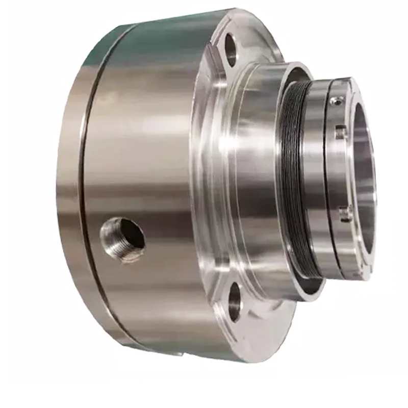
boiler feed water pump mechanical seal free sample

Die Erfindung betrifft eine Gleitringdichtung für Kesselspeisepumpen zur Förderung von Heißwasser mit einer Temperatur von über 100 °C.The invention relates to a mechanical seal for boiler feed pumps for pumping hot water with a temperature of over 100 ° C.
Bisher werden Kesselspeisepumpen der genannten Art mit mechanischen Gleitringdichtungen ausgerüstet, die auch als hydrodynamische und thermohydrodynamische Dichtungen bezeichnet werden. Es handelt sich dabei um Dichtsysteme, bei denen eine Berührung oder zumindest eine partielle Berührung zwischen der rotierenden und der stationären Dichtfläche der Gleitringdichtung auftritt. Dabei ist vielfach in die die Gleitringdichtung aufnehmende Dichtungskammer eine Fördereinrichtung integriert, beispielsweise eine Förderschnecke, ein Pumpring oder eine Schleppscheibe, die einen zum größten Teil extern verlaufenden Wasserkreislauf zu der hier unverzichtbaren Kühlung der Gleitringdichtung antreibt. Notwendige Bestandteile dieses Kühlkreislaufes sind ein Wasser/Wasser-Wärmeaustauscher, Filtereinrichtungen, Armaturen und Überwachungsgeräte.So far, boiler feed pumps of the type mentioned have been equipped with mechanical mechanical seals, which are also referred to as hydrodynamic and thermohydrodynamic seals. These are sealing systems in which there is contact or at least partial contact between the rotating and the stationary sealing surface of the mechanical seal. In this case, a conveyor device, for example a screw conveyor, a pump ring or a drag disk, which drives a largely external water circuit to cool the mechanical seal, which is indispensable here, is integrated into the seal chamber receiving the mechanical seal. The necessary components of this cooling circuit are a water / water heat exchanger, filter devices, fittings and monitoring devices.
Bereits heute werden Kesselspeisepumpen hergestellt, die Gleitgeschwindigkeiten von mehr als 50 m/s im Bereich der Gleitringdichtung erreichen. Bei derart schnell laufenden Pumpen müssen aus dem Bereich der Gleitringdichtung Wärmeleistungen von weit über 20 kW abgeführt werden, um die Dichtung ausreichend zu kühlen. Nur bei ausreichender Kühlung ist sichergestellt, daß der Dichtspalt so weit wie möglich mit Wasser gefüllt ist und die Übergangsgrenze zur Dampfphase möglichst nahe am atmosphärenseitigen Spaltaustritt liegt.Boiler feed pumps are already being manufactured today that achieve sliding speeds of more than 50 m / s in the area of the mechanical seal. With such high-speed pumps, heat outputs of well over 20 kW must be removed from the area of the mechanical seal in order to cool the seal sufficiently. Only with sufficient cooling can it be ensured that the sealing gap is filled with water as far as possible and that the transition limit to the vapor phase is as close as possible to the gap on the atmosphere side.
Die Zylinderreibung der Dichtungsteile, die eigentliche Dichtspaltreibung und die Wärmeleitung der heißen Pumpenbauteile in Richtung des Dichtungsgehäuses.The cylinder friction of the sealing parts, the actual sealing gap friction and the heat conduction of the hot pump components in the direction of the sealing housing.
Eine störungsfreie Funktion der Gleitringdichtung ist davon abhängig, daß die aus den verschiedenen Quellen stammende Wärme zuverlässig so weit reduziert wird, daß die Wassertemperatur im Dichtungsbereich nicht über ca. 50 bis 65 °C ansteigt.A trouble-free function of the mechanical seal is dependent on the heat coming from the various sources being reliably reduced to such an extent that the water temperature in the seal area does not rise above approx. 50 to 65 ° C.
Ein weiteres Problem ist bei Gleitringdichtungen dieser Bauart dadurch gegeben, daß Gasanteile im Fördermedium im Dichtlippenbereich auszentrifugiert werden und dadurch die unverzichtbare Kühlung der Dichtlippe so verschlechtern, daß die Gleitringdichtung durch thermische Überlastung vorgeschädigt wird, wenn nicht gar ausfällt.Another problem with mechanical seals of this type is that gas components in the pumped medium are centrifuged in the area of the sealing lips and thereby deteriorate the indispensable cooling of the sealing lip so that the mechanical seal is damaged by thermal overload, if not fails.
Die der Erfindung zugrundeliegende Aufgabe besteht darin, den mit den geschilderten steigenden Anforderungen an die Gleitringdichtungen entstehenden Problemen mit einer Lösung zu begegnen, die nicht in einer weiteren Steigerung des vor allem für die Kühlung zu treibenden Aufwandes besteht, sondern den für einen sicheren Betrieb der Gleitringdichtung notwendigen Aufwand nach Möglichkeit reduziert.The object on which the invention is based is to counter the problems which arise with the increasing demands made on the mechanical seals with a solution which does not consist in a further increase in the effort which is to be made primarily for cooling, but in the safe operation of the mechanical seal necessary effort reduced if possible.
Die gestellte Aufgabe wird erfindungsgemäß gelöst durch eine gasgeschmierte Gleitringdichtung, wobei auf eine Kühlung der Gleitringdichtung verzichtet wird und Mittel zur Absenkung des in der die Gleitringdichtung aufnehmenden Dichtungskammer herrschenden Druckes unter den Dampfdruck des geförderten Heißwassers vorgesehen sind.The object is achieved according to the invention by a gas-lubricated mechanical seal, cooling of the mechanical seal being dispensed with and means for lowering the pressure prevailing in the seal chamber receiving the mechanical seal below the vapor pressure of the pumped hot water are provided.
Statt den für die Kühlung notwendigen Aufwand mit den steigenden Anforderungen zu erhöhen, können die für die geschilderte Problematik verantwortlichen Bedingungen genutzt werden, wenn anstelle einer flüssigkeitsgeschmierten Gleitringdichtung eine sogenannte Gasdichtung eingesetzt wird. Für den Betrieb einer solchen Dichtung muß lediglich sichergestellt werden, daß das abzudichtende Medium an der Gleitringdichtung in Dampfform vorliegt. Da dieses Medium Heißwasser ist, das bereits bei dem außerhalb der Kreiselpumpe herrschenden Druck verdampfen würde, bedarf es nur noch eines vergleichsweise geringen Aufwandes, um der geltenden Bedingung zu genügen. Ein teilweise extern verlaufender Kreislauf ist hierbei nicht mehr notwendig.The invention is based on the following consideration:
Instead of increasing the effort required for cooling with increasing requirements, the conditions responsible for the problems described can be used if a so-called gas seal is used instead of a liquid-lubricated mechanical seal. For the operation of such a seal, it is only necessary to ensure that the medium to be sealed is in vapor form on the mechanical seal. Since this medium is hot water, which would already evaporate at the pressure prevailing outside the centrifugal pump, only a comparatively small effort is required to meet the current condition. A partially external cycle is no longer necessary.
Der Anwender der Erfindung kann sich bei der Maßnahme, das abzudichtende Heißwasser in den gasförmigen Aggregatzustand zu versetzen, auf bekannte physikalische Vorgänge stützen. Zu beachten ist hierbei der Zusammenhang zwischen der Temperatur und dem Dampfdruck einer Flüssigkeit. So läßt sich die Verdampfung des Heißwassers sowohl durch die Zufuhr weiterer Wärme als auch durch eine Druckabsenkung erreichen. Die Unteransprüche nennen verschiedene Mittel zur Erzielung des genannten Zweckes, wobei diese Mittel einzeln oder in Kombination miteinander eingesetzt werden können.The user of the invention can rely on known physical processes for the measure of putting the hot water to be sealed in the gaseous state of matter. Note the relationship between the temperature and the vapor pressure of a liquid. The evaporation of the hot water can be achieved both by adding more heat and by reducing the pressure. The subclaims name various means of achieving the stated purpose, which means can be used individually or in combination with one another.
Eines dieser Mittel besteht darin, zwischen dem Pumpeninneren und der Dichtungskammer der Gleitringdichtung eine hoch wirksame Drosselvorrichtung anzuordnen, deren Leckage kleiner ist als die Leckage der Gleitringdichtung, so daß der Druck vor der Gleitringdichtung durch Entspannung abgesenkt wird. Eine derartige Drosselvorrichtung kann beispielsweise durch eine radiale Spaltdichtung gebildet werden, wie sie durch den Prospekt "Radiale Spaltdichtung statt Labyrinth - bis zu 90 % weniger Leckage" der Firma Feodor Burgmann, Wolfratshausen bekannt geworden ist.One of these means is to arrange a highly effective throttle device between the pump interior and the seal chamber of the mechanical seal, the leakage of which is less than the leakage of the mechanical seal, so that the pressure in front of the mechanical seal is reduced by relaxation. Such a throttle device can be formed, for example, by a radial gap seal, as is known from the brochure "Radial gap seal instead of labyrinth - up to 90% less leakage" from Feodor Burgmann, Wolfratshausen.
Der Druck in der Dichtungskammer kann auch durch eine Pumpeinrichtung abgesenkt werden. Hierzu ist zwischen dem Pumpeninneren und der Dichtungskammer eine Förderschnecke, ein Kreiselpumpenlaufrad oder eine mit Pumpbohrungen versehene Scheibe angeordnet, deren Förderung von der Dichtungskammer zum Pumpeninneren hin gerichtet ist.The pressure in the sealing chamber can also be reduced by a pump device. For this purpose, a screw conveyor, a centrifugal pump impeller or a disk provided with pump bores is arranged between the pump interior and the sealing chamber, the delivery of which is directed from the sealing chamber to the pump interior.
Schließlich kann auch vor der Dichtungskammer eine Wärmequelle angeordnet sein, durch welche das abzudichtende Heißwasser vor seinem Übertritt in die Dichtungskammer in den Dampfzustand versetzt wird.Finally, a heat source can also be arranged in front of the sealing chamber, by means of which the hot water to be sealed is brought into the vapor state before it passes into the sealing chamber.
Die Verwendung gasgeschmierter Gleitringdichtungen in Kreiselpumpen ist grundsätzlich bekannt. So lehrt die DE 37 22 110 A 1 eine bei ungestörtem Betrieb einer Kreiselpumpe mitlaufende Hilfsdichtung, die durch Luft aus der umgebenden Atmosphäre geschmiert wird. Die Luft wird durch Schleppnuten in der Dichtfläche des umlaufenden Gleitringes in den Dichtspalt gefördert, wo sie ein Polster geringer Dicke bildet. Bei einem Ausfall der vorgeschalteten Hauptdichtung gelangt das Fördermedium der Kreiselpumpe zu der Hilfsdichtung, die nun als flüssigkeitsgeschmierte Gleitringdichtung arbeitet. Die während des ungestörten Betriebes in den Dichtspalt geführte Luft dient somit nicht der Abdichtung, sondern sie soll lediglich ein Anlaufen der Gleitringe dieser außer Funktion befindlichen Dichtung verhindern.The use of gas-lubricated mechanical seals in centrifugal pumps is generally known. For example, DE 37 22 110 A 1 teaches an auxiliary seal that rotates when a centrifugal pump is operating undisturbed and is lubricated by air from the surrounding atmosphere. The air is conveyed into the sealing gap by drag grooves in the sealing surface of the circumferential slide ring, where it forms a cushion of small thickness. If the upstream main seal fails, this happens Pump medium from the centrifugal pump to the auxiliary seal, which now works as a liquid-lubricated mechanical seal. The air that is led into the sealing gap during undisturbed operation is therefore not used for sealing, but is merely intended to prevent the seal rings of this seal which is not functioning from tarnishing.
Anhand eines Ausführungsbeispiels wird die Erfindung näher erläutert. Die Zeichnung zeigt eine Schnittdarstellung einer in einer Kesselspeisepumpe angeordneten erfindungsgemäßen Gleitringdichtung.The invention is explained in more detail using an exemplary embodiment. The drawing shows a sectional view of a mechanical seal according to the invention arranged in a boiler feed pump.
Die Gleitringdichtung wird gebildet durch einen Gleitring 1, der in einem das Gehäuse 2 der Kesselspeisepumpe abschließenden Deckel 3 angeordnet ist, und einen Gegenring 4, der mit der Welle 5 der Kesselspeisepumpe umläuft.The mechanical seal is formed by a mechanical ring 1, which is arranged in a cover 3 that closes the housing 2 of the boiler feed pump, and a counter ring 4, which rotates with the shaft 5 of the boiler feed pump.
Einer die Gleitringdichtung 1, 4 umgebenden Dichtungskammer 6 ist eine als Förderschnecke ausgebildete Pumpeinrichtung 7 vorgeschaltet. Die Pumpeinrichtung 7 übt eine Förderwirkung in Richtung eines Raumes 8 aus, der einem den Innenraum der Kesselspeisepumpe abschließenden Drosselspalt 9 nachgeschaltet ist. Die Förderwirkung hat zur Folge, daß in den Bereich der Pumpeinrichtung 7 gelangendes Medium aus dem Inneren der Kreiselpumpe nur unter Druckverlust in die Dichtungskammer 6 zu gelangen vermag. Dieser Druckverlust ist so hoch, daß evtl. noch als Heißwasser in die Pumpeinrichtung 7 gelangendes Medium in die Dampfphase versetzt wird. Somit gelangt in den Dichtspalt zwischen Gleitring 1 und Gegenring 4 allein gasförmiges Medium.A pump device 7 designed as a screw conveyor is connected upstream of a sealing chamber 6 surrounding the mechanical seal 1, 4. The pump device 7 exerts a conveying action in the direction of a space 8 which is connected downstream of a throttle gap 9 which closes the interior of the boiler feed pump. The conveying effect has the result that medium entering the area of the pump device 7 from the interior of the centrifugal pump can only enter the sealing chamber 6 with a loss of pressure. This pressure loss is so high that any medium entering the pump device 7 as hot water is put into the vapor phase. Thus, only gaseous medium gets into the sealing gap between slide ring 1 and counter ring 4.
Unterstützend kann hierbei ein gezielt herbeigeführter Druckabfall in der Dichtungskammer 6 wirken. Zu erreichen ist dieser durch eine definierte Leckage der Gleitringdichtung 1, 4.A targeted drop in pressure in the sealing chamber 6 can act as a support. This can be achieved by a defined leakage of the mechanical seal 1, 4.
Über eine im Gehäuse 2 vorgesehene Bohrung 10 und eine daran anschließende - hier nur angedeutete - Leitung 11 wird Entlastungswasser, das sich im Raum 8 ansammelt, zur Saugseite der Kesselspeisepumpe hin abgeführt.Relief water, which accumulates in space 8, is discharged to the suction side of the boiler feed pump via a bore 10 provided in the housing 2 and an adjoining — here only indicated — line 11.
The cylinder friction of the sealing parts, the actual sealing gap friction and the heat conduction of the hot pump components in the direction of the sealing housing.
daß die Wassertemperatur im Dichtungsbereich nicht über ca. 50 bis 65°C ansteigt.A trouble-free function of the mechanical seal depends on the fact that the
Instead of increasing the effort required for cooling with increasing requirements, the conditions responsible for the problems described can be used if a so-called gas seal is used instead of a liquid-lubricated mechanical seal. For the operation of such a seal, it is only necessary to ensure that the medium to be sealed is in vapor form on the mechanical seal. Since this medium is hot water, which would already evaporate at the pressure prevailing outside the centrifugal pump, only a comparatively small effort is required to meet the current condition. A partially external cycle is no longer necessary.
einen Gegenring 4, der mit der Welle 5 der Kesselspeisepumpe umläuft.The mechanical seal is formed by a mechanical ring 1 , which is arranged in a cover 3 that closes the housing 2 of the boiler feed pump, and a counter ring 4 , which rotates with the shaft 5 of the boiler feed pump.
Dichtspalt zwischen Gleitring 1 und Gegenring 4 allein gasförmiges Medium.A pump device 7 designed as a screw conveyor is connected upstream of a sealing chamber 6 surrounding the mechanical seal 1 , 4 . The pump device 7 exerts a conveying action in the direction of a space 8 which is connected downstream of a throttle gap 9 which closes the interior of the boiler feed pump. The conveying effect has the result that medium entering the area of the pump device 7 from the interior of the centrifugal pump can only enter the sealing chamber 6 with a loss of pressure. This pressure loss is so high that any medium entering the pump device 7 as hot water is put into the vapor phase. Thus, only gaseous medium gets into the sealing gap between slide ring 1 and counter ring 4 .
der Gleitringdichtung 1, 4.A targeted drop in pressure in the sealing chamber 6 can act as a support. This can be achieved by a defined leakage of the mechanical seal 1 , 4 .
ansammelt, zur Saugseite der Kesselspeisepumpe hin abgeführt.Relief water, which accumulates in space 8 , is discharged to the suction side of the boiler feed pump via a bore 10 provided in the housing 2 and an adjoining — here only indicated — line 11 .

We recognize and understand the vital role of boiler feed water pump mechanical seal in their application. With purposes including securely fastening components within systems, and contaminants prevention such as gases and liquids from navigating through enclosed and sealed areas. That is why we offer wholesale boiler feed water pump mechanical seal in different variations and diversities to ensure the integrity and efficiency of systems they will be applied to will function successfully and optimally. The different seals" types available include static that does not move along with other seals and dynamic seals that move collaboratively.
Depending on the industry and selected purpose, we consider boiler feed water pump mechanical seal requirements. Requirements are like pressure, that is pressure changes, to ensure they can withstand and do not deform by the sealed fluid, the load and how it can withstand deflection, dynamics such as the alignment and vibration, and temperature covering the environmental conditions and the heating arising from the friction of the seal operation and fluid movement.
The seals are either bolts, nuts, or washers. Seal bots are commonly used because of their benefits in being reusable, preventing fluids and contaminants from escaping even under high pressure. Nuts are essential on temperature withstanding and compatibility with screws, studs, and bolts, in addition to, easy installation. Moreover, washers can withstand high pressures and are compatible with other seals.
Wear rings are an essential component of the subject pump’s design and application. Typically, the pump impeller will have wear ring surfaces that are either renewable or integral; the casing will have stationary wear rings that mate with each impeller rotating wear ring. The radial running clearance between the two rings affects the internal recirculation of the process water in the pump. The amount of fluid that recirculates across the ring clearance has a direct effect on the pump’s efficiency.
In a construction using C-6 material there will typically be 400 series stainless steel wear rings in the pump. The pump manufacturer will harden the 400 series rings so that there is at least a 50 Brinell hardness differential between the impeller and casing wear rings which helps prevent galling between the two rings during operation. Running clearance on these rings can be quite high at an elevated temperature. API 610 recommends running clearances greater than the pump OEM manufacturer’s clearances, especially as process temperature increases. High running clearances can provide improved reliability over time. As dry running a pump with metallic rings installed can cause catastrophic failure to the pump in less than one minute, special measures should be taken to prevent dry running the pump when metallic wear rings are installed.
Today there are a number of options on wear ring materials for customers to choose from in lieu of the traditional metal-to-metal ring combinations. Over the past two decades there have been many composite thermoplastic wear ring materials that have been introduced to the market. These composite materials are typically used on the stationary casing wear ring component. The composite material is installed inside of the metal ring as shown here. Composite material is also recommended for the stationary center bushing component on the API 610 BB3 design. Most composite rings can operate up to 500°F, allowing it to operate in most Boiler Feed Water applications.
With a composite wear ring on the stationary ring, running clearances can be taken to much tighter values, when compared to a metal-to- metal ring clearance. For example, the API 610 requires a .020” diametrical running clearance on a ring that is 8.000 inches to < 9.000 inches in diameter. Composite wear rings can accommodate a .011” diametrical running clearance on that same ring dimension. This ultimately improves the efficiency of the pump. In addition to its ability to run a tighter clearance, the composite ring also has a low coefficient of friction. This low coefficient prevents excessive heat buildup during an upset or temporary dry run condition. There are many case studies in the industry which show customers who have prevented a catastrophic and costly pump failure by having composite stationary wear rings installed on their pumps.
Composite rings come at a price. They can often add $15,000-$25,000 to the cost of a large API 610 BB3 pump. I will add that not all composite wear rings materials are created equal. Some will have different radial thermal expansion properties than others. It is encouraged that a pump subject matter expert conduct research before one decides on the type of composite ring material to use. Finally, caution is strongly recommended if using composite wear rings material in fluids with high solids content. If there is heavy scale or high solids in the boiler feed water, it is best to stay away from the composite ring materials. The thermoplastic base material can wear quickly in a high solids environment.

Since 2007, the hot-filament Chemical Vapor Deposition (CVD) technology for crystalline diamond thin-film coatings has found its way into the mechanical seal market to combat the problems of dry running, corrosion and abrasion. This new technology has proved successful in hundreds of pumping applications in a wide range of services and duties. The reliability and lifetime of mechanical seals are improved by using diamond-coated faces. One such application involved the sealing of large boiler feed and steam generator pumps in power plants. The duty conditions for the pump’s seals can be as high as pressures up to 580 psig (40 bar), shaft RPMs up to 6,500 and temperatures up to 400˚F (200˚C). Consequently, the mechanical seal faces are highly loaded in a fluid with far less than ideal lubricating qualities. It is evident, therefore, that these applications are technologically challenging for mechanical seal manufacturers not only from a tribological perspective, but also from a corrosion viewpoint when the feed water has a low electrical conductivity or is free of impurities. This paper discusses a new seal-face treatment using hotfilament CVD manufacturing technology tested in a lab for 16,000 hours and currently used in feed pump operations in several power stations in the USA and Europe.

They serve to feed a steam generator such as a boiler or a nuclear reactor with a quantity of feed water corresponding to the quantity of steam emitted. Today, all boiler feed pumps are
Until 1950, the average pressure in the outlet cross-section of the pump (discharge pressure of the feed pump) was in the 200 bar region. By 1955 the average discharge pressure had risen to 400 bar. The mass flow rates were in the region of 350 tonnes/h in 1950, compared to 3200 tonnes/h (in some exceptions up to 4000 tonnes/h) today. Boiler feed pumps operate at fluid
Feed pumps for 1600 MW nuclear power stations are constructed for mass flow rates of up to 4000 tonnes/h and feed pump discharge pressures of 70 to 100 bar.
Until 1950 approximately, boiler feed pumps were made of unalloyed steels; since then they have been made of steels with a chrome content of 13 - 14 %. This change of materials was made necessary by the introduction of new chemical feed water compositions. The development of highstrength, corrosion and erosion resistant martensitic chrome steels with good anti-seizure properties as well as the continuous development of all pump components (bearings, shaft seal, pump hydraulic system, etc.) paved the way for present-day boiler feed pumps with rotational speeds of 4500 to 6000 rpm.
The mass flow rates of centrifugal pumps rose rapidly in conjunction with the rise of unit outputs in power stations. Today"s full load feed pumps for conventional 800 to 1100 MW power station units are constructed with four to six stages with stage pressures of up to 80 bar. Feed pumps for 1600 MW nuclear power stations are of the single-stage type.
In the case of conventional power stations above 500 MW full load feed pumps are increasingly driven by steam turbines. In most cases condensing turbines running at 5000 to 6000 rpm are used.
Electric motors usually drive part load feed pumps, both in fossil-fuelled and in nuclear power stations. Speed control of electrically driven feed pumps is effected by either fluid coupling (e. g. variable speed turbo couplings) or by electrical closed-loop control systems by means of thyristors (up to a drive rating of approximately 18 MW in 2011).
The low-speed booster pump is usually driven by the free shaft end of the turbine via a step-down gear or directly by the free end of the electric motor. See Fig. 2 Boiler feed pump
The single or double suction booster pump serves to generate the necessary NPSHR of the system for the high-speed boiler feed pump connected downstream. Fig. 3 Boiler feed pump
Two aspects of deciding between a ring-section and a barrel pull-out pump are described below:The smaller the mass flow rate and the higher the pressure, the higher the material and manufacturing costs of barrel pull-out pumps. This does not apply to the same extent to ring-section pumps.
Barrel pull-out pumps have some advantages over ring-section pumps when it comes to repairing a pump installed in the system. If a rotor has to be replaced, the barrel (see Pump casing) can remain installed in the piping. This is significant with regard to the
In the case of nuclear power stations, single-stage feed pumps with double-entry impeller (see Double-suction pump) and double volute casing are usually adopted. See Fig. 6 Boiler feed pump
Cast pressure-retaining casing parts are increasingly replaced by forged parts. As an example, such a feed pump could be designed with a flow rate of about 4200 m3/h and a head of about 700 m at a rotational speed of 5300 rpm. See Fig. 5 Boiler feed pump
Heads of reactor feed pumps are in the region of 800 m for boiling water reactors and 600 m for pressurised water reactors. The flow rates are about twice as high as those of a comparable boiler feed pump in a fossil-fuelled power station.
For boiler feed pumps two factors have to be considered regarding the wall thickness of the casing: the pressure loads and the different temperature conditions it needs to withstand. These two criteria are satisfied by adopting a high-strength ferritic casing material which enables the wall thickness to be kept thin enough to avoid any overloads as a result of temperature fluctuations, yet of adequate thickness to guarantee the requisite safety against internal pressure.
Barrel casingThe casings of barrel pull-out pumps and barrel casing pumps are usually made of unalloyed or low-alloyed ductile forged steel. Deposit welding is used on all surfaces in contact with the feed water to coat them with corrosion and erosion resistant material.
In order to weld the pump into the piping, an adapter must be provided if the materials of the nozzles to be connected are from different material groups.
The discharge-side (discharge pressure containing) barrel cover is fastened by means of large non-torqued studs. Sealing is provided by a profile joint which is pressurised purely by the prevailing pressure (of up to several 100 bar) without any external forces acting on it. See Fig. 7 Boiler feed pump
Ring-section pumpsThe casings of ring-section pumps are preferably made of forged chrome or carbon steel plated with austenitic (iron solid solution) material.
The sealing element between the individual stage casings (see Stage) seals off by metal-to-metal contact, the individual casings being clamped together axially by tie bolts between the suction and discharge casings (see Pump casing).
A common feature of barrel pull-out pumps and ring-section pumps is that the greater the wall thickness, the greater the thermal stress caused by thermal shocks, which in turn reduces the service life of the pump. The provision of injection water at a pressure situated between the suction and discharge pressure of the pump is a frequent requirement. This is taken care of by tapping water from one of the pump stages of both barrel pull-out pumps and ring-section pumps.
Tapping a stage of a boiler feed pumpIn the case of ring-section pumps, a partial flow at an intermediate pressure can easily be tapped through a tapping nozzle in one of the stage casings.
In the case of barrel pull-out pumps, the inside of the barrel is divided into three pressure zones so that a partial flow at the required intermediate pressure can be led off directly to the outside. See Fig. 4 Barrel pull-out pump
The sealing function is taken care of by a profile joint between the discharge and the tapping pressure, and by a metal-to-metal joint between the tapping and the inlet pressure. See Fig. 7 Boiler feed pump
The pump shaft of boiler feed pumps has a very small static deflection as the bearings are spaced as closely as possible, the shaft diameter is relatively large and thevibrations and runs smoothly (seeAxial thrust) which have to be absorbed by the balancing device.
The rotors of single-stage reactor feed pumps are even stiffer than those of boiler feed pumps, and their static deflection is smaller than that of multistage boiler feed pumps.
The magnitude of this axial thrust depends on the position of the operating point, on the characteristic curve, the rotational speed and the amount of wear on the internal clearances (see Controlled gap seal). Additional disturbing forces can arise in the event of abnormal operating conditions, e.g. cavitation.
On larger boiler feed pumps the axial forces at the pump rotor are balanced by means of a hydraulic balancing device through which the fluid handled flows. The balancing device is often combined with an oil-lubricated thrust bearing (see Plain bearing). As this balancing device absorbs more than 90 % of the axial thrust, a relatively small thrust bearing can be used. The balancing device may comprise a balance disc with balance disc seat, or a balance drum or double drum with the corresponding throttle bushes.
Axial thrusts arising in reactor feed pumps with double-entry impeller (see Double-suction pump) are balanced hydraulically; residual thrusts are absorbed by an oil-lubricated thrust bearing. See Fig. 6 Boiler feed pump
Radial forces arise from the weight of the rotor, mechanical unbalance or hydraulic radial thrust. The radial forces are balanced by two oil-lubricated radial bearings as well as by throttling clearances through which the fluid handled flows in axial direction. Such throttling clearances are located at the impeller neck on the impeller inlet side, or in the case of multistage boiler feed pumps for conventional power stations on the discharge side of the impeller (interstage bush) and at the balance drum. If the rotor is in an off-centre position, a re-centring reaction force will be generated in these clearances, which largely depends on the pressure difference and the clearance geometry (LOMAKIN effect).
The LOMAKIN effect is severely reduced when, due to abnormal operating conditions, the feed water in the clearance is not in a purely liquid phase (see Cavitation).
The hydrostatic action of the clearances contributes more to reducing shaft deflection than the mechanical stiffness does. The system is designed in such a way that operating speed always remains well away from the critical speed of the rotor, allowing hydraulic exciting forces (particularly in low flow operation) to be absorbed in addition.
Common shaft seals for boiler feed pumps are mechanical seals, floating ring seals and labyrinth seals. Gland packings are less common these days. (Also see Shaft seal).
Transient or low flow operating conditions cause additional loads on boiler feed pumps. This leads to additional stresses and strains as well as to deformation of components with various consequences on their functionality.
Nowadays, almost all boiler feed pumps must be able to handle both cold starts (high-temperature shock loads) and semi-warm starts without any damage. In these start-up procedures hot feed water abruptly flows into the cold pump, which results in the inner components heating up much faster than the pressure boundary. Depending on the frequency of starts and the gradient curves of pressure and temperature (load cycles) this can shorten the service life of the pump.
Contact between parts of thestator cannot, generally, be ruled out as narrow clearances are used as controlled gap seals This applies to the impeller neck on the impeller inlet side, the discharge-side clearance between impeller,
In operating conditions with a very low or zero flow, e.g. in the turning gear mode of a turbine-driven boiler feed pump, temperature layers establish in the fluid handled, which may cause deformation of the rotors and, after a slight delay, also of the non-rotating components. Once the clearance gaps are closed the rotor will be subjected to a significantly higher friction moment, leading to overload of the turning gear and to standstill of the pump. In this case, the temperature will no longer be equalised at the rotor, which will further aggravate the rotor deformation.
This can result in several hours of downtime for the pump. Usually the only remedy is to let the machine cool down to reduce or eliminate the critical temperature layers and the deformation.
Avoid large differences in temperature in and on the pumpThermally separate the cold areas (shaft seal area) from the area through which the hot fluid passes (hydraulic system and balancing device) by means of an insulation chamber system; provide a thermal seal to prevent convection flows and special thermosleeves.
The above measures are frequently used for barrel casing pumps (barrel pull-out pumps) as their outer dimensions, wall thickness, drive (turbine with turning gear) and operating modes are considered more critical than those of ring-section pumps. If possible, these measures are always automated to safeguard the availability of the pump set.
A minimum flow valve (automatic recirculation valve) ensures a minimum flow rate and thus prevents damage which could occur in low flow operation as a result of either an impermissible increase in temperature leading to vaporisation of the pump content or low flow cavitation.

In the beginning, water ran freely over the Earth. Then, man made pumps to make water run where he wanted it. Then came leaks. Then, man made pump seals. And as time went on, man still continued to struggle with leaking pump seals.
For those who are new to pump maintenance and repair, mechanical seals can be intimidating—given their reputation as temperamental devices that fail frequently. In fact, they are simple devices that are often misapplied and sometimes poorly installed or used on pumps that are ill-suited for the application. For many applications, mechanical seals are robust enough to tolerate less-than-optimal handling and operating conditions. For more demanding applications, though, everything must be right.
It is important to review how a pump mechanical seal works. First, its main components are the rotating and stationary face rings that form the primary seal (Image 1). The face rings have flat, precision-smooth contact surfaces that are held in tension against each other by mechanical springs.
The rotating face ring and its assembly have to be sealed to the shaft. The stationary face ring has to be sealed to the housing. These two sealing points are called secondary seals and typically use elastomer O-rings or boots (Image 2).
Selecting the proper materials for the primary and secondary seal components is important. For common water pumping applications, carbon-ceramic face material and Buna-N secondary seals are standard and work well. Alternate materials work better for pumping sewage or strong chemicals, so many technicians seek outside help on these applications.
By following a few precautions, it is not difficult to install pump mechanical seals during the repair process. For example, to ensure the elastomer secondary seals will slide into place undamaged, always use the proper lubricant. Some seal providers offer water-soluble lubricants designed for this purpose. Make sure the lubricant is water-soluble (except with oil-filled seal chambers), so that it will be washed away by pump operation.
In all cases, avoid damaging the elastomer secondary seals on the edges of shaft shoulders, keys or housings. A good way to accomplish this is to wrap a sheet of mylar paper around the shaft to protect the seal as it is slid into place.
While the amount of tension the seal spring assembly applies can be a concern on some special applications, the tension adjustment on common utility pumps is preset by the pump and seal design. Just observe during disassembly if there are any tensioning provisions and, if so, document the measurements.
When a seal leakage problem occurs, carefully inspect the seal to determine the cause. Is it leaking at the primary seal or at one of the secondary seals? The wear pattern of primary seal faces should be smooth and slightly shiny, and the elastomer secondary seals should be pliable but not soft. The shaft and housing contact surfaces should be corrosion free; corrosion at those contact points would indicate a leak.
If the cause of a problem is difficult to determine, many value-added seal providers can analyze seal failures, ask critical questions about the application and recommend products that will perform best. Their prices may be more than some alternatives, but their value added is the knowledge to spec the right product.
If unsure about how to find a good, value-added seal provider, do an internet search for “industrial pump seals” in the required zip code. In major metropolitan areas, there are probably three or four likely prospects. Ask each of them for a seal for a boiler feedwater pump (or other tough application). If they only ask for the pump ID or the dimensions but not the temperature, pressure or other application parameters, they probably will not be much help. Users may get a great price, but on the wrong product.
Eugene Vogel is a pump and vibration specialist at EASA, Inc. in St. Louis, Missouri. He may be reached at 314-993-2220. EASA is an international trade association of more than 1,800 firms in nearly 70 countries that sell and service electromechanical apparatus. For more information, visit easa.com.

www.watertechonline.com is using a security service for protection against online attacks. An action has triggered the service and blocked your request.

www.watertechonline.com is using a security service for protection against online attacks. An action has triggered the service and blocked your request.

In order to understand centrifugal pump leakage, it’s important to first understand the basic operation of a centrifugal pump. As the flow enters through the impeller eye of the pump and up the impeller vanes, the fluid is at a lower pressure and low velocity. When the flow passes through the volute, the pressure increases and the velocity increases. The flow then exits through the discharge, at which point the pressure is high but the velocity slows. The flow that goes into the pump has to go out of the pump. The pump imparts head (or pressure), which means it increases the energy of the pump fluid.
Certain component failures of a centrifugal pump, such as coupling, hydraulic, static joints, and bearings, will cause the whole system to fail, but approximately sixty-nine percent of all pump failures result from the sealing device malfunctioning.
A mechanical seal is a device that is used to control leakage between a rotating shaft and a liquid- or gas-filled vessel. Its main responsibility is to control leakage. All seals leak—they have to in order to maintain a fluid film over the entire mechanical seal face. The leakage that comes out the atmospheric side is fairly low; the leakage in a Hydrocarbon, for example, is measured by a VOC meter in parts/million.
Before mechanical seals were developed, engineers typically sealed a pump with mechanical packing. Mechanical packing, a fibrous material usually impregnated with a lubricant such as graphite, was cut into sections and stuffed down what was called a “stuffing box.” A packing gland was then added to the backside in order to pack everything down. Since the packing is in direct contact with the shaft, it requires lubrication, but will still rob horsepower.
Usually a “lantern ring” allows flush water to be applied to the packing. That water, necessary to lubricate and cool the shaft, will leak either into the process or into the atmosphere. Depending on your application, you may need to:
As with every pump, you’ll want to test your pump to discover the annual costs it requires to run. A packing pump may be affordable to install and maintain, but if you calculate how many gallons of water it consumes per minute or per year, you may be surprised by the cost. A mechanical seal pump could potentially save you a lot of annual costs.
If the centrifugal pump exhibits an uncontrolled leak, you must thoroughly check all potential causes to determine if you need repairs or a new installation.
Neglecting the Best Efficiency Point: Are you operating the pump at the Best Efficiency Point (BEP) on a performance curve? Each pump is designed with a specific Efficiency Point. When you operate the pump outside that region, you create problems with the flow that cause the system to fail.
Insufficient Net Positive Suction Head (NPSH): If you don’t have enough suction head to your pump, the rotating assembly can become unstable, cause cavitation, and result in a seal failure.
Operating Dead-Headed: If you set the control valve too low to throttle the pump, you can choke the flow. Choked flow causes recirculation within the pump, which generates heat and promotes a seal failure.
Dry Running & Improper Venting of Seal: A vertical pump is the most susceptible since the mechanical seal is positioned on top. If you have improper venting, air can get trapped around the seal and won’t be able to evacuate the stuffing box. The mechanical seal will soon fail if the pump continues to run in this condition.
Low Vapor Margin: These are flashing fluids; hot hydrocarbons will flash once exposed to atmospheric conditions. As the fluid film passes across the mechanical seal, it can flash at the atmospheric side and cause a failure. This failure often happens with boiler feed systems—hot water at 250-280ºF flash with the pressure drop across the seal faces.
Shaft misalignment, coupling imbalance, and impeller imbalance can all contribute to mechanical seal failures. In addition, after the pump is installed, if you have misaligned pipes bolted to it, you will impart a lot of strain on the pump. You also need to avoid a bad base: Is the base secure? Is it grouted properly? Do you have a soft foot? Is it bolted correctly? And last, check the bearings. If the tolerance of the bearings wears thin, the shafts will move and cause vibrations in the pump.
Do you have a good tribological (the study of friction) pair? Have you chosen the correct facing combinations? What about the seal face material quality? Are your materials appropriate for your specific application? Have you selected the proper secondary seals, such as gaskets and o-rings, that are prepared for chemical and heat attacks? Your springs should not be clogged or your bellows corroded. Last, keep an eye out for face distortions from pressure or heat, since a mechanical seal under great pressure will actually bow, and the skewed profile can cause a leak.
You need a proper seal flush arrangement, along with sufficient cooling. Dual systems have barrier fluids; the auxiliary seal pot needs to be in the right location, with the correct instrumentation and piping. You need to take the Length of Straight Pipe at Suction into account—some older pump systems that often came as a packaged skid include a 90º elbow at suction right before the flow enters the impeller eye. The elbow causes a turbulent flow that creates instabilities in the rotating assembly. All the suction/discharge and bypass piping needs to be engineered correctly as well, especially if some pipes have been repaired at some point over the years.
Other miscellaneous factors account for only about 8 percent of all failures. For example, auxiliary systems are sometimes required to provide an acceptable operating environment for a mechanical seal. For reference to dual systems, you need an auxiliary fluid to act as a barrier that prevents contamination or process fluid from spilling into the environment. However, for most users, addressing one of the first four categories will hold the solution they need.
Mechanical seals are a major factor in rotating equipment reliability. They’re responsible for leaks and failures of the system, but they also indicate problems that would eventually cause serious damage down the road. Seal reliability is greatly affected by the seal design and the operating environment.
Frank Rotello is mechanical seal reliability engineer for Cummins-Wagner. Cummins-Wagner Co., Inc. is a distributor for industrial and mechanical equipment covering the mid-Atlantic states with leading brands of compressors, pumps, and heat transfer equipment, and offer support services such as system design, assembly, and aftermarket service and repair. For more information, visit www.cummins-wagner.com.

The mechanical seal is one of the most important components of a pumping system. As the name suggests, the seal is a simple component that forms a barrier between the motor and the volute of a pump, protecting the motor against leakage.
Leakage is death to any mechanical instruments and pumps are no exception. Fluid leakage often results in corrosion of the casings, sleeves and bearings. Corrosion left unattended over a period of time will will degrade the construction material of the pump. Fluid leakage that enters the motor shaft can short circuit the motor.
Naturally, these problems will impede proper pump functioning and eventually could stop the pump from running altogether. Companies often spend a lot in terms of money, wasted manpower and lost operational time to fix leakage.The mechanical seal is designed to prevent that leakage from ever happening. Mechanical seal shaft failure is the number one cause of pump downtime according to WaterWorld magazine.
Submersible wastewater pumps, such as sewage pumps, are particularly susceptible to the dangers of leakage as their operation depends on being surrounded by water that may contain potentially corrosive or clogging waste solids. This water can accumulate in the motor casing and obviously a submersible pump cannot be drained without interrupting operation.
A wide variety of seal types are available for any number of applications. The type of seal most commonly used in sewage pumps is an end face mechanical seal.
In an end-faced seal two ringed “faces” or seal heads rest flat against each other (but are not attached) in the seal chamber, which is located between the volute (the “wet end” of the pump) and the motor. An actuator, such as a spring, presses the faces close to each other.
The rotating motor is inserted through the two ringed faces and attached to the impeller. As the motor shaft rotates, the upper seal (closer to the motor) rotates with the shaft. The bottom seal closer to the volute remains stationary.
This action creates a sealing interface which keeps the water in the volute and prevents leakage. A minimal amount of water might escape the sealing interface but this liquid essentially acts as a lubricant for the seal and will eventually evaporate from heat.
All the components of an end faced mechanical seal work in unison to prevent leakage and are equally important to proper functioning. The main components are:
1. The primary seal faces that rest against each other. The primary seal faces are typically made of durable materials such as silicon carbide, ceramic carbide or tungsten. Certain materials work better for certain applications. For instance, silicon carbide is resistant to acidic liquids, less so to alkaline liquids. Generally, face materials should be of high hardness and should have the ability to slide on each other.
2. Secondary seal surfaces or faces. The secondary faces surround the primary seal faces, but do not rotate. The secondary surfaces hold the primary faces in place and create an additional barrier. Secondary faces can come in a variety of forms – examples include o-rings, elastomers, diaphragms, mating rings, gaskets and wedges. The secondary face also allows for shaft deflection and misalignment.
3. Actuator or a means of pressing the seal faces together and keeping the entire seal properly aligned to the shaft. Often (but not always) a loaded spring. The actuator is mounted above the seal face closer to the motor while the motor shaft passes through the spring.
Mechanical seals are precise, sensitive and temperamental instruments. Even seemingly minor mishandling can negate the seal’s functionality. Therefore Pump Products highly recommends leaving the mounting and installation of mechanical seals to qualified technicians.
Before you actually handle your mechanical seal, be sure to wash your hands thoroughly. Because the faces are meant to be extremely flat, even small particles from the oil of human hands can damage the surface integrity of the faces and render the seal useless. Make sure to wipe the seal itself with an alcohol solution, in case another person touched the seal faces during the packing or shipping process.
The following is a basic guide to replacing a defective mechanical seal. Each seal should come with its own specific instructions, but this is overview covers the most essential parts of the mounting process.
2. Carefully remove the old seal head, taking care not to scratch the motor shaft. Take note of how the seal was mounted; the new seal will be mounted in the same manner.
Mechanical seals are classified by construction type and the construction type is expressed through a letter code. The seal listing code will designate the construction material of each component. For example, here is a construction code guide from U.S. Seal:
The construction materials of the seal will in turn inform what specific seal is suited for your specific pumping application. You can consult a material recommendation chart to best choose the right mechanical seal.
The above chart is a guide to identifying and sizing the appropriate mechanical seal for your pump. Because seals are specifically engineered instruments, making sure that the seal is properly sized for a specific pumping system and application is critical. Manufacturers often make specific recommendations for the type of material to use for an application as well – a recommendation chartis helpful.
A mechanical seal is simply a method of containing fluid within a vessel (typically pumps, mixers, etc.) where a rotating shaft passes through a stationary housing or occasionally, where the housing rotates around the shaft.
When sealing a centrifugal pump, the challenge is to allow a rotating shaft to enter the ‘wet’ area of the pump, without allowing large volumes of pressurized fluid to escape.
To address this challenge there needs to be a seal between the shaft and the pump housing that can contain the pressure of the process being pumped and withstand the friction caused by the shaft rotating.
Before examining how mechanical seals function it is important to understand other methods of forming this seal. One such method still widely used is Gland Packing.
Packing needs to press against the shaft in order to reduce leakage – this means that the pump needs more drive power to turn the shaft, wasting energy.
The stationary part of the seal is fitted to the pump housing with a static seal –this may be sealed with an o-ring or gasket clamped between the stationary part and the pump housing.
The rotary portion of the seal is sealed onto the shaft usually with an O ring. This sealing point can also be regarded as static as this part of the seal rotates with the shaft.
One part of the seal, either to static or rotary portion, is always resiliently mounted and spring loaded to accommodate any small shaft deflections, shaft movement due to bearing tolerances and out-of-perpendicular alignment due to manufacturing tolerances.
The primary seal is essentially a spring loaded vertical bearing - consisting of two extremely flat faces, one fixed, one rotating, running against each other. The seal faces are pushed together using a combination of hydraulic force from the sealed fluid and spring force from the seal design. In this way a seal is formed to prevent process leaking between the rotating (shaft) and stationary areas of the pump.
If the seal faces rotated against each other without some form of lubrication they would wear and quickly fail due to face friction and heat generation. For this reason some form of lubrication is required between the rotary and stationary seal face; this is known as the fluid film
In most mechanical seals the faces are kept lubricated by maintaining a thin film of fluid between the seal faces. This film can either come from the process fluid being pumped or from an external source.
The need for a fluid film between the faces presents a design challenge – allowing sufficient lubricant to flow between the seal faces without the seal leaking an unacceptable amount of process fluid, or allowing contaminants in between the faces that could damage the seal itself.
This is achieved by maintaining a precise gap between the faces that is large enough to allow in a small amounts of clean lubricating liquid but small enough to prevent contaminants from entering the gap between the seal faces.
The gap between the faces on a typical seal is as little as 1 micron – 75 times narrower than a human hair. Because the gap is so tiny, particles that would otherwise damage the seal faces are unable to enter, and the amount of liquid that leaks through this space is so small that it appears as vapor – around ½ a teaspoon a day on a typical application.
This micro-gap is maintained using springs and hydraulic force to push the seal faces together, while the pressure of the liquid between the faces (the fluid film) acts to push them apart.
Without the pressure pushing them apart the two seal faces would be in full contact, this is known as dry running and would lead to rapid seal failure.
Without the process pressure (and the force of the springs) pushing the faces together the seal faces would separate too far, and allow fluid to leak out.
Mechanical seal engineering focuses on increasing the longevity of the primary seal faces by ensuring a high quality of lubricating fluid, and by selecting appropriate seal face materials for the process being pumped.
When we talk about leakage we are referring to visible leakage of the seal. This is because as detailed above, a very thin fluid film holds the two seal faces apart from each other. By maintaining a micro-gap a leak path is created making it impossible for a mechanical seal to be totally leak free. What we can say, however, is that unlike gland packing, the amount of leakage on a mechanical seal should be so low as to be visually undetectable.


 8613371530291