
calpeda mechanical seal free sample

Therefore, we may say that with the GQV 65 pumps, Calpeda has ushered in, among its products, a new line destined to grow further, namely that of the dirty water drainage pumps for the industrial sector.
As for the construction features, here are some of the main aspects that highlight the excellent hydraulics and the careful mechanical design of the GQV 65 pump.
• The pump is equipped with double mechanical seal on a stainless-steel shaft with an oil chamber interposed for a safe protection of both the engine and against accidental dry running.

We are a manufacturer. All seals have bulk inventory and can be shipped to you quickly. We promise to ship you in small quantities within 3 days.Advanced technology, excellence, replace original
1. Different models of mechanicals seals for a wide variety of Grundfos® pumps, among them: CR(N), NB, NK, CLM, LP, TP, etc. Available in diverse combinations of materials and different diameters: 12, 16, 22, 28, 33, etc. Also mechanical seals for Sarlin®. Division of waster pumps. Available in various materials: silicon-graphite carbide, silicon carbide-silicon carbide; combined with EPDM and FKM elastomers.
2. Mechanical seals are available for different references Gorman-Rupp® pumps. Special models for the transfer of clean water, sewage, oil industry, agriculture and others.
3. Mechanical seals for Fristam® pumps. Wide range of models and materials in the most standard diameters: 22,30 and 35 mm. Different assembly possibilities for the most well-known pump models: FP, FL and FT.
4. Broad range of mechanical seals compatible with Flygt® and Grindex® waste water pumps. These mechanical seals are characterized by their easy and fast installation, without having to make any modification to the pump. Manufactured in stainless steel and in solid tungsten carbide. Special tools are not necessary for their installation.
6. Different designs of mechanical seals for Ebara® pumps, single and double seals in combinations carbide-silicon carbide and graphite-aluminium oxide.
7. Mechanical seals for all types of Calpeda®pumps: centrifugal pumps, multistage, submersible. Different models of mechanical seals in a wide range of materials.
9. Mechanical seals for ABS® submergible pumps specific wastewater treatment. Different models of mechanical seal available: oil chamber mechanical seal and water mechanical seal.
Seals with shaft size 0, 1, 1.375, 2, 2.25, 15 mm, 16 mm, 17 mm, 22 mm, 23 mm, 26 mm, 27, 30 mm, 35 mm, 37.5, 38 mm, 39 mm, 43 mm, 47, 53, 55 mm, 57, 58, 60 mm, 63, 68, 73, 75 mm, 80 mm, 90 mm, 100 mm, 110, 120, 125, 180, 189, 192, 200, 206, 230, 242, 270, 300, 335, 385
Mechanical seals are available in a variety of sizes, including 0 or 1 or 1.375 or 2 or 2.25 or 15 mm or 16 mm or 17 mm or 22 mm or 23 mm or 26 mm or 27 or 30 mm or 35 mm or 37.5 or 38 mm or 39 mm or 43 mm or 47 or 53 or 55 mm or 57 or 58 or 60 mm or 63 or 68 or 73 or 75 mm or 80 mm or 90 mm or 100 mm or 110 or 120 or 125 or 180 or 189 or 192 or 200 or 206 or 230 or 242 or 270 or 300 or 335 or 385. Selecting the right size mechanical seal is important for optimal performance and reliability. A mechanical seal with the correct shaft size ensures an accurate and secure fit on the pump shaft, distributing pressure correctly and preventing leakage.
Each mechanical seal has a unique type number, including 13, which is used to identify it and to indicate specific features and performance specifications. For example, the type number 13 may indicate material selection, size, pressure and temperature characteristics, or suitability for specific applications.
Initial costs and life cycle costs affect which sealing method is chosen for an application. If a sealing device cannot be considered an investment or will not produce an immediate return, there is little incentive for a change or upgrade.
Environmental stewardship can also play a role in choosing a sealing method. States and provinces have instituted heavy mandates that strictly control water consumption and effluent discharge. In some industries, water controls the environment in which the sealing method operates and plays an important part in increasing seal reliability. With the added concern of water reduction mandates, usage fines and the potential negative impact on reliability process industries are faced with doing more with less.
Spending logically upfront, increasing reliability while lowering operational costs are a winning combination achieved with sealing knowledge and Best Available Techniques (BAT).
The BAT approach is based on optimized economics and what makes sense for the user. It is dictated by equipment design, realistic seal life cycles, slurry characteristics and budget. Equipment with less than desirable sealing life cycles and the hard-to-seal equipment should be the area of focus. Sealing knowledge of when to use what technology i.e., mechanical packing or mechanical seals is critical to the BAT process. The sealing approach determined through BAT will optimize upfront costs while meeting expected life cycles.
The old 80/20 rule applies. A small population of the equipment can represent a large portion of the sealing costs associated with sealing bad actors or hard-to-seal equipment in slurry processes.
Dewatering slurries have lower densities. A paper pulp application is a perfect example of slurry, which will collect at low flow, less turbulent areas closest to the seal gland where the sealing device resides. This dewatering effect will insulate sealing device or block the flow of water, thus supporting a dry run condition and generating excess heat.
Most equipment in the slurry industries is large. It can be sealed with reliable, time efficient split sealing solutions that save money, production and labor hours. Split sealing can be economically justifiable when all life cycle costs are considered.
Today’s advanced sealing technologies include reliable high-performance split mechanical seals combined with environmental controllers, heavy duty, non-split, flushless cartridge seals or high-strength mechanical packing designed specifically for harsh abrasive slurry sealing.
The BAT approach to sealing considers the best sealing technologies, which contain slurry features inherent in their design increasing reliability, but also allows the reduction or elimination of flush water.
A mechanical seal design that places the springs entirely outside the seal will deliver higher performance levels. In slurry applications the slurry will migrate or precipitate across the seal faces. This is an uncontrollable event. Springs located entirely outside the seal (visible springs) will avoid the fouling that takes place internally and continue to deliver the closing force required to keep the faces tracking properly.
Micropolishing the dynamic o-ring surface is a process that improves the surface finish that the o-ring has to travel. The surface is manufactured to a mirror-like finish to reduce the friction between the o-ring and the dynamic sealing surface. Proper seal face tracking will continue over the life of the seal. Non-settling and dewatering type applications can insulate seal faces and increase the heat buildup. As a result, o-ring properties can be affected, limiting their sealing performance and introducing a problem with seal face hang-up.
In heavy slurry applications seal faces must be protected from possible impact of large solids, which can be as hard as rock. Seal face encapsulated in metal shrouds for protection is desirable.
Seal fouling on the both the process and atmospheric sides of the sea will occur. On the process side there are areas of low flow or low turbulence. It is here where the slurry can dewater and/or insulate the seal from the cooling effects of the process. As previously mentioned, fouling on the atmospheric side of the seal is an uncontrollable event.
Mechanical packing designed for challenging abrasive slurry environments can meet expected life cycles. Historically, the perception has been that packing required flush water for cooling, lubrication and cleaning for reliable operation in slurry services. High tensile strength materials are used to withstand abrasion but often exhibit less than ideal heat generation, thermal conductivity and chemical resistance characteristics. Users typically use high flush water rates to minimize the negative impact of these characteristics of slurry packing. High performance slurry pump packing can reduce flush water use and increase reliability. Pump packing constructed with graphite and carbon has proven successful in difficult slurry services. High tensile strength carbon yarns provide the reinforcement necessary to resist wear and abrasion in slurries while graphite provides sealing and lubrication. The carbon/graphite construction delivers low heat generation with high thermal conductivity, requiring less water for cooling. This unique construction of yarns yields a packing that is easily removable during repack, resulting in reduced downtime. The ability to be used in a wide array of equipment, using advanced materials and construction practices, packing can lower flush water requirements and deliver greater life cycles. Packing can represent a reliable low cost alternative in the slurry markets.
Environmental controllers are economical additions to mechanical seals and mechanical packing. Environmental controller bushings are designed to extend the life of sealing devices. They perform the function of expelling solids from a seal chamber using a spiral groove. As a result, less flush water is required to support a sealing method. In some instances, seal life cycles can be significantly increased and flush water completely eliminated. A number of environmental controller variations are available for the various sealing methods mentioned.
Dual seals are often used to increase seal life cycles in slurry applications. They can be a relatively high expense on upfront acquisition and utility cost. Dual seals offer the ability to pressurize a clean fluid, sometimes called barrier fluid, between two sets of seal faces. This arrangement is described as Plan 53 or Plan 54. Plan 53 uses a seal support tank to supply barrier fluid to the seal; Plan 54 uses an outside source, or flow through arrangement. In both, the pressure is set to a minimum of 15 psig (1 bar g) above the seal chamber pressure. This sealing approach ensures that a clean fluid is forced between the inboard set of seal faces, which would otherwise be the slurry in a single seal installation. Plan 54 can be an area for significant water reduction improvements since the flow through arrangement is associated with wasteful, high water flow rates to drain. Another area for savings is a means to reduce process dilution. Visibility to inboard seal leakage can be achieved with addition of a dual flowmeter. To evaluate the BAT opportunities at a plant, work with a single point supplier that is knowledgeable in all the sealing technologies mentioned. A supplier can deliver BAT, considering all of the following:
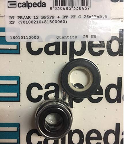
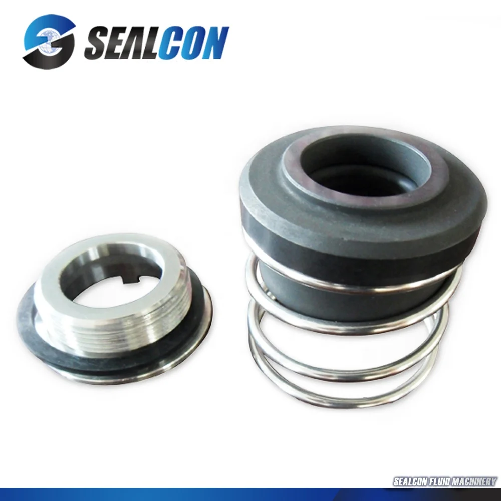
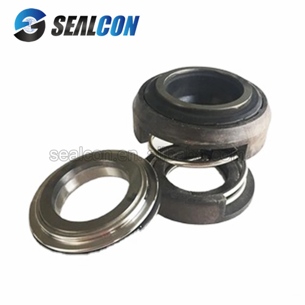
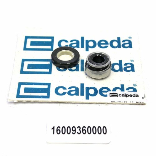
The pumps CALPEDA (Kalpeda) are mainly equipped with mechanical seals with a conical spring R-BT-FN and R-BT-FN.NU. To buy a mechanical seal for CALPEDA, you need to know the type designation "BT / FN" or the vendor code of the pump. Our seals are selected according to the sample, according to the vendor code of the CALPEDA pump or according to the marking of Burgmann, Roten, AESSEAL and other seal manufacturers.
For large differences sealing pressure ratio hydraulic unloading and load factor are almost identical. Dynamic friction auxiliary seals pr generally not taken into account.
By the term "sliding pressure" means the contact pressure on the sliding surfaces remaining after equilibration of all active forces on the sealing surface of the hydraulic pressure. Sliding pressure pG depends on pressure difference, coefficient of hydraulic unloading, a ratio of pressure in a sealing gap (pressure gradient indicator and spring pressure.
For seals with a sealing gap narrowing in the leakage direction (V-shaped gap) when loading external pressure indicator k1 can take values greater than 0,5, and for sealing with a sealing gap widening in the leakage direction (A-shaped gap) when loading an external pressure indicator k1 can be set to less than 0,5. To simplify the calculations are commonly used value of k1 = 0,5. Pressure slip under adverse conditions may take a negative value, which leads to the sealing surfaces of the joint disclosed and hence to excessive leakage.
Coefficient of friction f depends on the type of material of the friction pair, the type of sealing medium, the slip rate and the conditions of contact between the sliding surfaces due to construction.
For the general reasons and calculations it is necessary to use approximate coefficient of friction from 0,05 to 0,08. In the conditions of the improved lubricant, for example, at some increase in hydrodynamic pressure in a sealing gap, value of coefficient of friction decreases.
On the other hand, in a purely hydrodynamic mode of the mechanical seal and increasing the rotational speed to be expected to increase the coefficient of friction, as is the case with sleeve bearings under similar conditions.
For contact with the end seals theoretically strictly parallel sealing surfaces in the gap distance between them depends primarily on the roughness of these surfaces. The results are set measurements made in experimental and practical conditions have shown that when calculating the permissible leakage considering external factors necessary to take the average value of the height of the gap h less than 1 micron.
When using non-contact mechanical seal, unloaded hydrostatically or hydrodynamically, the gap height is automatically set. The height of the gap depends mainly on the shape of the gap in the radial and in the circumferential direction on the operating conditions and environment.
Influence of turbulence affects only at district speeds over 30 m/s. Turbulence power loss Pv should be considered especially in the case of special seals.
Estimated value of the leakage Q and the power loss are approximate.This statistical averages derived from numerous experiments and tests. For real actual seal leakage and power loss can be many times greater than estimated due to the presence of factors that can not be taken into account in the calculation. As can be seen from the formula, the leakage is mainly determined by the actual height of the gap, established in the course of work. This in turn depends on many factors.

A mechanical seal is simply a method of containing fluid within a vessel (typically pumps, mixers, etc.) where a rotating shaft passes through a stationary housing or occasionally, where the housing rotates around the shaft.
When sealing a centrifugal pump, the challenge is to allow a rotating shaft to enter the ‘wet’ area of the pump, without allowing large volumes of pressurized fluid to escape.
To address this challenge there needs to be a seal between the shaft and the pump housing that can contain the pressure of the process being pumped and withstand the friction caused by the shaft rotating.
Before examining how mechanical seals function it is important to understand other methods of forming this seal. One such method still widely used is Gland Packing.
The stationary part of the seal is fitted to the pump housing with a static seal –this may be sealed with an o-ring or gasket clamped between the stationary part and the pump housing.
The rotary portion of the seal is sealed onto the shaft usually with an O ring. This sealing point can also be regarded as static as this part of the seal rotates with the shaft.
One part of the seal, either to static or rotary portion, is always resiliently mounted and spring loaded to accommodate any small shaft deflections, shaft movement due to bearing tolerances and out-of-perpendicular alignment due to manufacturing tolerances.
The primary seal is essentially a spring loaded vertical bearing - consisting of two extremely flat faces, one fixed, one rotating, running against each other. The seal faces are pushed together using a combination of hydraulic force from the sealed fluid and spring force from the seal design. In this way a seal is formed to prevent process leaking between the rotating (shaft) and stationary areas of the pump.
If the seal faces rotated against each other without some form of lubrication they would wear and quickly fail due to face friction and heat generation. For this reason some form of lubrication is required between the rotary and stationary seal face; this is known as the fluid film
In most mechanical seals the faces are kept lubricated by maintaining a thin film of fluid between the seal faces. This film can either come from the process fluid being pumped or from an external source.
The need for a fluid film between the faces presents a design challenge – allowing sufficient lubricant to flow between the seal faces without the seal leaking an unacceptable amount of process fluid, or allowing contaminants in between the faces that could damage the seal itself.
This is achieved by maintaining a precise gap between the faces that is large enough to allow in a small amounts of clean lubricating liquid but small enough to prevent contaminants from entering the gap between the seal faces.
The gap between the faces on a typical seal is as little as 1 micron – 75 times narrower than a human hair. Because the gap is so tiny, particles that would otherwise damage the seal faces are unable to enter, and the amount of liquid that leaks through this space is so small that it appears as vapor – around ½ a teaspoon a day on a typical application.
This micro-gap is maintained using springs and hydraulic force to push the seal faces together, while the pressure of the liquid between the faces (the fluid film) acts to push them apart.
Without the pressure pushing them apart the two seal faces would be in full contact, this is known as dry running and would lead to rapid seal failure.
Without the process pressure (and the force of the springs) pushing the faces together the seal faces would separate too far, and allow fluid to leak out.
Mechanical seal engineering focuses on increasing the longevity of the primary seal faces by ensuring a high quality of lubricating fluid, and by selecting appropriate seal face materials for the process being pumped.
When we talk about leakage we are referring to visible leakage of the seal. This is because as detailed above, a very thin fluid film holds the two seal faces apart from each other. By maintaining a micro-gap a leak path is created making it impossible for a mechanical seal to be totally leak free. What we can say, however, is that unlike gland packing, the amount of leakage on a mechanical seal should be so low as to be visually undetectable.


 8613371530291